Ingo Maurer Pierre ou Paul Istruzioni per l'uso
- Tipo
- Istruzioni per l'uso

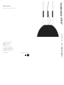
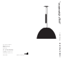
Pièrre ou Paul
Ingo Maurer und Team 1996
Ingo Maurer GmbH
Kaiserstrasse 47
80801 München
Germany
T. +49. 89. 381606-0
F. +49. 89. 381606 20
www.ingo-maurer.com
März 2019 Made in Germany
LED Instructions

54
Montageanleitung
Bitte vor der Montage aufmerksam lesen und
aufbewahren!
Instructions for Assembly
Please read these instructions carefully before going
any further, and keep them in a safe place for future
reference!
Instructions de montage
A lire attentivement avant le montage et à conserver!
Istruzioni di montaggio
Prima del montaggio leggere attentamente le
istruzioni e conservarle!
Deutsch Seite 4
English Page 9
Français Page 14
Italiano Pagina 20
Zeichnungen Seite 26
Drawings Page 26
Dessins Page 26
Disegni Pagina 26

76
Montage und Elektroanschluss müssen von einer Elektro -
fachkraft ausgeführt werden. Wir empfehlen, die Montage
mit zwei Personen durchzuführen.
Pierre ou Paul ist ein handwerklich hergestelltes Produkt.
Abweichungen in Oberflächenstruktur, Größe oder Form
des Objekts sind herstellungstechnisch bedingt und ein
gewünschter Teil der Gestaltung.
Wichtig: Die Leuchte hat ein Gesamtgewicht von ca.
18 kg. Bitte überprüfen Sie die ausreichende Tragfähigkeit
der Decke. Achten Sie auf adäquate Befestigungsmittel
entsprechend der jeweiligen Deckenkonstruktion.
Achtung: Schalten Sie vor der Montage die Sicherung
des Deckenauslasses aus! Achten Sie unbedingt auf den
Verlauf von Elektroleitungen, damit auf keinen Fall ein
Kabel angebohrt wird. Montieren Sie nicht auf feuchtem
und leitendem Untergrund!
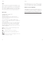
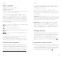
Montage des Baldachins und der Umlenkrollen
Legen Sie die Position des Baldachins (1) so fest, dass
das Kabel des Deckenauslasses durch die große Baldachin-
öffnung ragt. Benutzen Sie den Baldachin als Schablone
zum Markieren der Bohrlöcher. Bohren Sie drei Dübel-
löcher Ø 8 mm, setzen Sie die Dübel (2) ein und schrauben
Sie den Baldachin mit beiliegenden Schrauben (3) fest. 1
Zum Markieren der drei Seilaufhängungen halten Sie die
mitgelieferte Bohrschablone so an die Decke, dass der
Baldachin durch die Öffnung in der Mitte der Schablone
ragt. Durch Drehen der Bohrschablone können Sie die
gewünschte Position festlegen. Markieren Sie alle drei
Bohrungen. Bohren Sie drei Löcher Ø 8 mm für die drei
Umlenkrollen (4) und setzen Sie die beiliegenden Dübel (5)
oder gegebenenfalls Schwerlastdübel ein.
Deutsch Deutsch
Schrauben Sie die Umlenkrollen inklusive der
Beilagscheiben (6) fest in die Dübel ein. 1
Richten Sie die Laufrichtung der Umlenkrollen zur Mitte
des Baldachins.
Achtung: Überprüfen Sie den festen Sitz jeder Umlenk-
rolle an der Decke, bevor Sie die Kuppel mit den Gewichten
daran aufhängen!
Einsetzen der Elektromontage in die Kuppel
Wichtig: Bitte packen Sie die Aluminiumkuppel (7) vor-
sichtig aus und tragen Sie die mitgelieferten Baumwollhand-
schuhe, da die Flächen sehr empfindlich gegen mechanische
Einwirkungen sind.
Beachten Sie ebenfalls, daß weder das Leuchtenkabel,
noch die Stahlseile an die Kuppel-Innenseite gelangen
dürfen. Die Innenfläche ist sehr kratzempfindlich
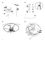
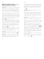
In der Kuppel ist ein Ring (8) mit drei Drähten eingespannt.
Halten Sie die Elektromontage (9) und das Schutzgitter (11)
von unten dagegen und schrauben Sie beides mit den drei
Schrauben (10) am Ring fest, wie in Zeichnung 2 darge-
stellt. Beachten Sie, dass das Schutzgitter (11) zwischen
Ring (8) und Elektromontage (9) sitzen muss.
Aufhängen der Aluminiumkuppel und Anpassen
der Seillänge an die Raumhöhe
Für diesen Teil der Montage sind zwei Personen notwendig.
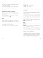
Legen Sie die Kuppel (7) unter dem Baldachin auf einen
Tisch, eine Kiste oder ähnliches – in etwa auf die gewünschte
Höhe. Fädeln Sie jeweils ein Seil (12) von unten durch
eines der Gewichte (13) und schieben Sie das Gewicht auf
dem Seil ganz nach unten zur Kuppel. Ziehen Sie das Seil
von innen nach außen durch eine Umlenkrolle (4).

98
Deutsch
Kürzen Sie das Seil mit einer Zange so, dass das lose Ende
wieder bis nach unten zum Gewicht reicht und stecken Sie
das Seilende von oben bis zum Anschlag in den Seilhalter
(14) des Gewichts. Verfahren Sie so mit allen drei Seilen.
3
Wichtig: Verwenden Sie zum Kürzen eine scharfe Zange
und achten Sie darauf, dass das Seil abgeschnitten und
nicht abgequetscht wird, da sich ansonsten das Seil auf-
spleißt und nicht mehr in den Seilhalter einführen lässt.
Die Kuppel hängt nun knapp über der vorherigen Stand-
fläche. Zum Kürzen der einzelnen Seile auf die endgültige
Länge hängen Sie nacheinander jeweils ein Gewicht aus.
Wichtig: Wählen Sie die Seillänge so, dass die Gewichte
ungefähr in der Mitte der Seile hängen (zwischen A und B).
Die zweite Person sollte das jeweils zu kürzende Seil durch
Anheben der Kuppel entlasten. Drücken Sie den Knopf des
Seilhalters ein und ziehen Sie das entlastete Seil aus dem
Seilhalter. Kürzen Sie das Seil auf die gewünschte Länge
und stecken Sie das Ende wieder tief in den Seilhalter. 3
Wichtig: Das Seil muss zwingend mindestens 3 cm tief in
den Seilhalter eingeführt werden!
Verwenden Sie den ersten Seilabschnitt als Maß für
die beiden anderen, um die identischen Seillängen
sicherzustellen. Kleinere Ungenauigkeiten können durch
Verschieben des Gewichts am Seilhalter ausgeglichen
werden.
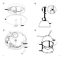
Einhängen des Sekundärreflektors
Fädeln Sie jeweils einen der Haken der 3 Haltedrähte
(25), von außen durch die Bohrungen im Rand des
Leuchtgehäuses (9).
Legen Sie dann den Sekundäreflektor (23) mit dem
äußeren Rand in die unteren Haken ein. 5
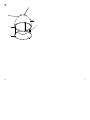
Elektroanschluss im Baldachin
Achtung: Schalten Sie die Sicherung des Deckenauslasses
aus!
Lassen Sie die abgemantelte Zuleitung des Deckenauslasses (15)
etwa 12 cm aus dem Baldachin ragen und isolieren Sie die
Enden der einzelnen Adern ca. 7 mm ab. Schließen Sie Leiter
und Neutralleiter auf der einen Seite der Lüsterklemme (16)
und den Schutzleiter am Erdungsnippel (17) der Käfigmutter
entsprechend der Markierung im Baldachin an. 4
Fädeln Sie das metallumhüllte Lampenkabel (18) durch
den Rändelnippel (19) und das Mittelloch der Abdeck-
scheibe (20) und anschließend durch die Käfigmutter (21)
in der Mitte des Baldachins. 1 + 4
Fädeln Sie das Kabel unter die Zugentlastungslasche (22).
Ziehen Sie das Kabel so weit in den Baldachin, dass es auch
bei tief hängender Kuppel in weichem Bogen fällt und
schrauben Sie die Zugentlastung fest. Schneiden Sie das
Kabel ca. 10 cm hinter der Zugentlastung ab und entfernen
Sie die Metallumhüllung bis kurz vor der Zugentlastung.
Schließen Sie die drei abisolierten Adern an den noch
freien Buchsen der Lüsterklemme (16) entsprechend der
Markierung an. 4
Schieben Sie die Abdeckscheibe (20) am Kabel nach oben
und schrauben sie mit dem Rändelnippel (19) an der
Kafigmutter (21) fest. 1
Pflege
Reinigen Sie die Außenseite der Aluminiumkuppel mit
einem weichen Tuch und gegebenenfalls mit einem milden
Reinigungsmittel. Sparen Sie dabei den Namensstempel aus.
Die Innenseite der Kuppel und das Gehäuse der
Lichtmontage können, nachdem sie vollständig ausgekühlt
sind, mit einem weichen Tuch gereinigt werden.
Achten Sie bitte darauf, die Flächen nicht mit bloßen
Händen zu berühren.
Deutsch

1110
Technische Daten
220-240V 50Hz. 3 x 16,5W LED
110-130V 60Hz. 3x15W
100V 60Hz. 3x15W
3x 15 W LED, 0,87cosᵩ, 3x1300 lm, 3000K, CRI>90.
Stufenlos dimmbar (siehe Geeignete Wanddimmer).
Mit eingebautem LED-Leuchtmittel, kann nicht vom Nutzer
ausgetauscht werden.
Das Leuchtmittel darf nur von der Ingo Maurer GmbH
oder einem von der Ingo Maurer GmbH beauftragten
Servicetechniker oder einer vergleichbaren qualifizierten
Person ersetzt werden.
A+ Die Leuchte wird verkauft mit einem Leucht-
mittel der Energieklasse A+.
Vorsicht; Gefahr vor elektrischem Schlag
Mindestabstand zu brennbaren Flächen: 1 m
Jedes zerbrochene Schutzglas muss unbedingt
ersetzt werden.
Eventuell notwendige Reparaturen dürfen nur von einer
Elektrofachkraft durchgeführt werden. Die äußere Leitung
darf bei Beschädigung nur von der Ingo Maurer GmbH
ausgetauscht werden.
Geeignete Wanddimmer
Die Leuchte kann mit einem speziellen Triac Dimmer
(Phasenanschnitt- und Phasenabschnittsteuerung) stufenlos
und fl immerfrei gedimmt werden. Aktuelle Empfehlungen
zu kompatiblen Dimmern entnehmen Sie bitte unserer
Internetseite: https://www.ingo-maurer.com/de/produkte/
pierre-ou-paul
Deutsch
The lamp assembly and all electrical work must be carried
out by a qualified electrician. We recommend that the
assembly be carried out by two people.
Pierre ou Paul is a hand-made product. Minor variations
in the surface structure, size and shape of the lamp are a
natural result of the production process and an intended
design feature.
Important: The lamp has a total weight of around 18
kg. Please make sure that your ceiling is capable of taking
the strain. Ensure that suitable fixing materials are used,
according to the ceiling construction.
Caution: Switch off or remove the fuse for the ceiling
outlet before beginning the assembly. Please take care to
ascertain the exact position of all electrical wiring, so as to
avoid accidentally drilling into a cable. Do not attach the
lamp to a damp and/or conductive surface!
Assembling the canopy and pulleys
Position the canopy (1) so that the mains cable from the
ceiling outlet protrudes through the large aperture in the
canopy. Use the canopy as a template to mark the drill
holes. Drill three 8 mm-diameter holes, insert the plugs (2)
and attach the canopy with the screws (3) provided. 1
To determine the fixture points for the suspension
wires, hold the drill template up to the ceiling so that the
canopy protrudes through the aperture in the centre of
the template, and mark the three drill holes, turning the
template to adjust the position of the fixture points as
required. Drill three 8 mm-diameter holes for the three
pulleys (4) and insert the plugs supplied (5) or, if necessary,
heavy-duty ceiling anchors. Screw the pulleys, with the
washers (6), firmly into the plugs or anchors. 1
Attach the pulleys so that they face the centre of the
canopy.
English

1312
Caution: Check that each pulley is securely fixed to the
ceiling before attaching the shade with the weights.
Inserting the electrical assembly in the shade
Important: Please be very careful when unpacking the
aluminium shade (7), and wear the cotton gloves supplied,
as the surfaces are easily damaged. Also note that neither
the lamp cable nor the steel cable must hang into the
opening of the aluminium shade.
The inner surface is very sensitive to scratches !
Inside the shade is a ring (8) with three wires. Hold the
electrical assembly (9) and the protective grid (11) up
against the ring and attach both with the three screws (10),
as shown in fig. 2. Please note that the protective grid
(11) has to be place between the ring (8) and the electrical
unit (9) .
Attaching the aluminium shade and adjusting
the cable length
Two people are needed for this part of the assembly.
Place the shade (7) on a table or other raised surface under
the canopy, so that the shade stands approximately at the
required height. Thread one of the cables (12) from below
through one of the weights (13) and push the weight down
along the cable towards the shade. Pull the cable through
one of the pulleys (4). Trim the cable with
a wire-cutter so that the loose end hangs down as far as
the weight and insert the end of the cable from above into
the holder (14) on the weight until it reaches the stop.
Repeat this procedure for the other two cables. 3
English English
Important: Use a sharp cutter to trim the cable and make
sure that the cut is clean. Do not crush or flatten the end
of the cable, as this will cause fraying and prevent insertion
in the holder.
The shade should now hang just above the surface on
which it was previously resting. For the final adjustment of
the cables to the required length, unhook the weights one
after the other.
Important: Select the suspension cable length so that the
weight hangs about half-way up the cable (between points
A and B).
The second person lifts the shade to slacken the cable to
be trimmed. Press the button on the cable holder and pull
the slackened cable out of the holder. Trim the cable to the
required length and replace the end firmly in the holder. 3
Important: The end of the suspension cable must be
pushed at least 3 cm into the holder!
Use the first cable as the guide for the others, so that the
lengths are identical. Slight irregularities can be corrected by
adjusting the position of the weight on the cable holder.
Electrical connection in the canopy
Caution: Switch off or remove the fuse for the ceiling
outlet.
Remove a 12 cm section of the outer covering from the
mains cable (15) protruding through the canopy, and strip
about 7 mm from the ends of the three wires. Connect
the phase and neutral wires to the contacts in the terminal
(16), and attach the earth wire to the earth contact (17)
on the cage nut, according to the markings in the canopy. 4

1514
Thread the metal-covered lamp cable (18) through the
knurled grip nut (19) and the aperture in the centre of the
canopy cover (20) and then through the cage nut (21) in
the centre of the canopy. 1 + 4
Feed the lamp cable under the strain relief (22). Pull the
cable into the canopy so that it can still fall in a loose arc
even when the shade hangs down low, and screw the strain
relief down tightly. Trim the cable about 10 cm from the
strain relief and remove most of the metal covering, leaving
only a short section just in front of the strain relief. When
stripping the cable approx. 4cm, please pay attention
that the sensitive insulation of the individual wires is not
damaged.
Insulate the wire ends by approx. 5 mm and use the
enclosed wire end ferrules. 4
Fix the protective conductor centrally, phase and neutral
according to the markings in the luster terminal (3)
Push the cover (20) up along the cable and screw the
knurled grip nut (19) with the cover into the cage nut (21)
in the centre of the canopy. 1
Mounting the secondary reflector
Thread the hook (25) of the holding wires from the
outside through the holes in the edge of the light housing
(9).
Then insert the secondary reflector (23) with the outer
edge into the lower hooks. 5
Cleaning
The outer surface of the aluminium shade can be cleaned
with a soft cloth, using a mild cleaning fluid if necessary. Do
not clean the name stamp.
The inner surface of the shade and the housing of the lamp
fitting can be cleaned with a soft cloth when they have
cooled down completely.
Do not touch the surfaces with your bare hands.
English English
Technical specification
220-240V 50Hz. 3 x 16,5W LED
110-130V 60Hz. 3x15W
100V 60Hz. 3x15W
The correct voltage and fre-quency for your lamp are
indicated on the type label.
3x 15 W LED, 0,87cosᵩ, 3x1300 lm, 3000 K, CRI>90.
Continuously dimmable (see Compatible wall dimmers,
below).
With built-in LEDs of energy class A+, which cannot be
replaced by the user. The light source of this lamp may only
be replaced by Ingo Maurer GmbH or a service technician
authorized by Ingo Maurer GmbH or a similar qualified
person.
A+ The lamp is supplied with an LED module of
energy class A+.
Caution; danger of electric shock
Minimum distance from combustible surfaces: 1 m
The protective glass cover must be replaced in
case of damage.
Any repairs that may become necessary must be carried
out by a professional electrician. In the event of damage to
the external power cord, replacements may only be fitted
by Ingo Maurer GmbH.
Compatible wall dimmers
The lamp can be connected to a special Triac (leading edge
or trailing edge phase control) dimmer for continuous and
fl icker-free operation. For current recommendations on com-
patible dimmers please see our website:
https://www.ingo-maurer.com/en/products/pierre-ou-paul

1716
Le montage et le branchement électrique sont à effectuer
par un électricien. Nous recommandons d’effectuer le
montage à deux personnes.
Pierre ou Paul est un produit confectionné à la main. Des
irrégularités dans la structure de la surface, la taille ou la
forme de l’objet sont dûes à la technique de production et
font partie du design.
Important: la lampe a un poids total d’environ 18 kg.
Veuillez contrôler la limite de charge du plafond. Vérifier
que les fixations soient adéquates à la construction du
plafond.
Attention: déconnecter le fusible contrôlant l’arrivée du
courant au plafond avant le montage! Il est indispensable de
respecter le positionnement des conduites électriques pour
éviter de percer un câble électrique. Ne pas installer sur
une surface humide et/ou conductrice!
Montage du baldaquin et des poulies de renvoi
Positionner le baldaquin (1) de telle manière à ce que
le câble de la sortie du plafond dépasse de la grande
ouverture du baldaquin. Utiliser le baldaquin comme gabarit
pour marquer les trous de perçage. Percer les trois trous
de cheville Ø 8 mm, insérer les chevilles (2) et visser le
baldaquin avec les vis jointes (3). 1
Pour marquer les trois câbles de suspension, tenir le gabarit
de perçage au plafond de façon à ce que le baldaquin sorte
de l’ouverture au centre du gabarit. En tournant le gabarit
de perçage, vous pouvez définir la position souhaitée.
Marquer les trois points de perçage. Percer trois trous de
Ø 8 mm pour les trois poulies de renvoi (4) et insérer
les chevilles jointes (5) ou le cas échéant les chevilles de
grande portée. Visser fermement les poulies de renvoi avec
leurs rondelles de calage (6) dans les chevilles. 1
Orienter le sens des poulies de renvoi vers le centre du
baldaquin.
Français
Attention: Vérifier la bonne tenue de chaque poulie de
renvoi au plafond avant d’y suspendre la coupole et ses
contre-poids !
Insertion du montage électrique dans la
coupole
Important: Déballer prudemment la coupole en
aluminium (5) en portant les gants de coton ci-joints, les
surfaces sont très sensibles aux actions mécaniques.
Notez également que ni le câble de la lampe ni le câble
en acier ne doivent pendre par le haut dans l‘ouverture du
coupole.
La surface intérieure est très sensible aux rayures !
Dans la coupole se trouve un anneau (8) auquel sont
tendus trois filins. Tenir le montage électrique (9) et la grille
de protection (11) par le bas et visser les deux fermement
avec les trois vis (10) à l’anneau, comme représenté sur
le dessin 2. Veillez à ce que la grille de protection (11)
soit bien positionnée entre l‘anneau (8) et le montage
électrique (9).
Suspension de la coupole en aluminium et
ajustement de la longueur des fils de suspension
à la hauteur de la pièce
Pour cette partie de montage, deux personnes sont
nécessaires. Positionner la coupole en aluminium (7)
sous le baldaquin sur une table, une caisse ou équivalent
– à la hauteur approximativement souhaitée. Enfiler
respectivement le fil (12) par le bas à travers l’un des
contre-poids (13) et déplacer le poids le long du fil
jusqu’au bas vers la coupole. Tirer le filin de l’intérieur
vers l’extérieur à travers une des poulies de renvoi (4).
Raccourcir le fil à l’aide d’une pince de telle manière à
ce que l’extrémité libre réatteigne le poids vers le bas; et
insérer l’extrémité du fil dans le porte-fil (14) du poids, par
le dessus jusqu’en butée. Agir de même avec les trois fils. 3
Français

1918
Français
Important: utiliser une pince coupante pour raccourcir les
fils et vérifier qu’ils soient coupés et non écrasés, car sinon
les fils s’effilocheraient et ne passeraient plus dans les porte-
fils.
La coupole est suspendue juste au-dessus de la surface
où elle se trouvait auparavant. Pour raccourcir le fil à la
longueur définitive, décrocher l’un après l’autre chaque
poids.
Important: déterminer la longueur de fil de telle manière
à ce que les poids soient suspendus environ au milieu des
fils (entre A et B).
La deuxième personne devra décharger le fil à raccourcir
en soulevant la coupole. Appuyer sur le bouton du porte-
fil et tirer le fil déchargé du porte-fil. Raccourcir le fil à la
longueur souhaitée et réinsérer l’extrémité en profondeur
dans le porte-fil. 3
Important: le fil doit être inséré obligatoirement à 3 cm
de profondeur dans le porte-fil!
Utiliser la 1ère section de filin comme unité de mesure
pour les deux autres filins, afin de garantir des longueurs
de câble identiques. Des petites inexactitudes peuvent être
rééquilibrées en déplaçant le poids sur le porte-fil.
Connexion électrique du baldaquin
Important: déconnecter le fusible de la sortie du plafond!
Faire dépasser du baldaquin la conduite dégainée de la
sortie du plafond (15) d’environ 12 cm et dénuder les
extrémités de chaque fil conducteur d’environ 7 mm.
Connecter le fil de phase et le fil neutre à l’un des côtés
du domino (16) et le fil de terre au raccord de mise à la
terre de l’écrou (17) correspondant au marquage sur le
baldaquin. 4
Enfiler le câble électrique de la lampe recouvert de métal
(18) à travers le raccord fileté molleté (19) et le trou
central du disque de recouvrement (20) et enfin à travers
l’écrou à cage (15) au centre du baldaquin. 1 + 4
Enfiler le câble sous la languette de décharge de trac-
tion (22).
Insérer le câble le plus loin possible dans le baldaquin,
de telle manière à ce qu’il retombe en formant un arc
léger, même si la coupole est suspendue très bas, et
visser la décharge de traction fermement. Couper le câble
environ 10 cm derrière la décharge de traction et ôter
le revêtement métallique jusque devant la décharge de
traction. Lors du dénudage du câble 4cm, veillez à ce que
l‘isolation sensible des différents fils n‘est pas
endommagée.
Isoler les extrémités des fils d‘env. 5 mm et utiliser la
méthode les embouts d‘extrémité de fil livrés avec
l‘appareil. Fermer le conducteur de protection au centre,
phase et neutre en conséquence des marquages dans la
borne de lustre (3). 2. 4
Déplacer le disque de recouvrement (20) sur le câble vers
le haut et visser le au raccord fileté molleté (19) avec le
disque de recouvrement à l’écrou à cage (21) au centre du
baldaquin. 1
Montage du réflecteur secondaire
Enfiler un des crochets de chacun des 3 fils de retenue (25)
de l‘extérieur à travers les trous dans le bord du boîtier de
l‘éclairage (9).
Insérer ensuite le réflecteur secondaire (23) avec le bord
extérieur dans les crochets inférieurs.
Français
5

2120
Français
Entretien
Nettoyer la surface extérieure de la coupole en aluminium
avec un chiffon souple et le cas échéant avec un nettoyant
doux. Ne pas nettoyer le nom tamponné.
La surface intérieure de la coupole et le boîtier du montage
électrique peuvent être nettoyés avec un chiffon souple,
une fois refroidis complètement.
Veuillez faire attention à ne pas toucher les surfaces à main
nue.
Données techniques
230 V~50 Hz; 125 V~60 Hz. Veuillez consulter la plaque
signalétique pour la tension et la fréquence appropriée pour
votre lampe.
3x 15 W LED, 201 mA, 0,87cosᵩ, 1300 lm, 3000 K, CRI>90.
Réglage en continu (cf Variateurs muraux compatibles).
Avec module LED intégré, ne peut pas être changée par
l‘utilisateur. Le module ne doit être remplacée que par la
société Ingo Maurer ou par un technicien commandité
par la société Ingo Maurer ou une personne ayant des
qualifi cations comparables.
A+ Cette lampe est équipée d‘un module LED intégré
de la classe énergétique A+.
Attention: danger d‘électrocution
Distance minimale aux surfaces inflammables: 1 m
Tout verre cassé doit être obligatoirement rem-
placé.
Des réparations éventuellement nécessaires ne doivent
être effectuées que par un spécialiste.
En cas d’endommagement, le câble électrique externe ne
doit être échangé que par la société Ingo Maurer GmbH.
Français
Variateurs muraux compatibles
L’intensité de lumière de la lampe peut être réglée en con-
tinu et sans scintillement par un variateur Triac spécial
(commande à coupe de phase ascendante ou descendante).
Veuillez s‘il vous plaît consulter sur notre site Internet nos
recommandations actuelles sur les variateurs compatibles:
https://www.ingo-maurer.com/fr/produits/pierre-ou-paul

2322
Italiano
Il montaggio e il collegamento elettrico devono essere
eseguiti da un elettricista. E’ consigliato effettuare il
montaggio in due persone.
Pierre ou Paul è un prodotto realizzato a mano. Differenze
di struttura della superficie, dimensioni e forma sono
intenzionali e un naturale risultato del procedimento di
produzione.
Importante: Il lampadario ha un peso complessivo di ca.
18 kg. Si prega di controllare preventivamente la portata
del soffitto. E’ importante provvedere a mezzi di fissaggio
adatti alla relativa costruzione del soffitto.
Attenzione: Prima del montaggio staccare la corrente
dell’uscita della corrente al soffitto! Fare assolutamente
attenzione al percorso delle linee di alimentazione per
evitare di danneggiare un cavo durante la foratura. Non
montare su superfici umide o conduttrici di corrente!
Montaggio del rosone e delle pulegge
Determinare la posizione del rosone (1) in modo che il
cavo dell’uscita della corrente a soffitto passi attraverso
l’apertura maggiore del rosone. Impiegare il rosone come
dima di foratura per contrassegnare i punti da forare.
Effettuare i tre fori per i tasselli di Ø 8 mm, inserire i tasselli
(2) e avvitare il rosone con le viti (3) in dotazione. 1
Per contrassegnare la posizione dei cavetti di sospensione,
sistemare la dima di foratura allegata sul soffitto accertan-
dosi che il rosone passi attraverso l’apertura centrale della
dima di foratura. Determinare la posizione desiderata ruo-
tando la dima di foratura. Contrassegnare i tre punti da
forare. Effettuare i tre fori per i tasselli di Ø 8 mm per le
tre pulegge di rinvio (4) e inserire i tasselli (5) in dotazione
oppure in caso di necessità tasselli per carichi pesanti.
Avvitare le pulegge di rinvio incluse le rondelle (6) salda-
mente nei tasselli. 1
Orientare le pulegge verso il centro del rosone.
Italiano
Attenzione: Prima di appendere la cupola con i contrappe-
si, è assolutamente necessario controllare il fissaggio saldo al
soffitto di ogni puleggia!
Inserimento dell‘unità elettrica nella cupola
Importante: Estrarre cautamente la calotta in alluminio (7)
dall’imballaggio e indossare i guanti in cotone allegati; le
superfici sono molto sensibili a sollecitazioni meccaniche.
Si noti inoltre che né il cavo della lampada né il cavo
d‘acciaio devono essere appesi dall‘alto nell‘apertura della
calotta. La superficie interna è molto sensibile ai graffi!
All’interno della cupola in alluminio è teso un anello (8) con
tre fili. Accostare dal basso l’unità elettrica (9) e la griglia
protettiva (11) e avvitare entrambe con le tre viti (10)
all’anello, come mostrato in figura 2.
Tenere presente che la griglia protettiva (11) deve essere
disposta tra l’anello (8) e l’unità elettrica (9).
Appendere la calotta in alluminio e adattare
la lunghezza del cavetto all’altezza del soffitto
Questa fase del montaggio deve essere eseguita da due
persone. Appoggiare la calotta (7) sotto il rosone su un
tavolo, una cassa o simili – all’incirca all’altezza desiderata.
Infilare ogni cavetto (12) dal basso attraverso uno dei
contrappesi (13) e far scorrere il contrappeso lungo il
cavetto verso il basso fino alla calotta. Passare il cavetto
attraverso la relativa puleggia di rinvio (4) dall’interno
verso l’esterno. Dunque accorciare il cavetto con una pinza
(tronchese) in modo che l’estremità libera dello stesso
coincida con la parte superiore del contrappeso e succes-
sivamente inserire l’estremità del cavetto dall’alto fino
all’arresto nel “gripper” ferma cavo (14) del contrappeso.
Procedere nello stesso modo per ognuno dei cavetti. 3

2524
Italiano
Importante: Per tagliare il cavetto metallico usare una
pinza adatta, che non lo schiacci ma lo tagli nettamente.
Se il cavetto è tagliato male e sfilacciato, si lascia molto
difficilmente inserire nel “gripper” ferma cavo.
A questo punto la calotta si trova leggermente sollevata
rispetto al suo piano d’appoggio. Per accorciare i singoli
cavetti alla lunghezza definitiva, bisogna sganciare un
contrappeso alla volta.
Importante: La posizione ideale del contrappeso è quella
equidistante tra il soffitto e la calotta (tra A e B).
La seconda persona deve sollevare la calotta per ottenere
che il rispettivo cavetto da accorciare non sia sotto
tensione. Premere il bottone del gripper ferma cavo ed
estrarre il filo libero dal gripper. Accorciare il cavetto alla
lunghezza desiderata e reintrodurre l’estremità del cavetto
a fondo nel ferma cavo. 3
Importante: Il cavetto deve assolutamente essere inserito
nel ferma cavo almeno 3 cm!
Impiegare il primo cavetto accorciato come esempio per
assicurare che gli altri due cavetti vengano accorciati in
misura equivalente. Piccole differenze di lunghezza possono
essere corrette spostando il contrappeso sul fermacavo.
Collegamento elettrico nel rosone
Attenzione: Staccare la corrente dell’uscita della corrente
al soffitto!
Lasciare spuntare la linea di alimentazione dell’uscita di cor-
rente a soffitto (15) di circa 12 cm dal rosone e spelare
le estremità dei singoli fili di circa 7 mm. Collegare fase e
neutro da un lato del morsetto (16) e la terra al raccordo
di terra (17) del dado gabbia secondo il segno sul rosone.
4
Infilare il cavo della lampada con rivestimento in metallo
(18) attraverso il raccordo zigrinato (19) e il foro centrale
del disco di copertura (20) e successivamente attraverso il
dado gabbia (21) al centro del rosone. 1 + 4
Infilare il cavo sotto il passante dello scarico di trazione
(22). Introdurre il cavo nel rosone assicurandosi che formi
un leggero arco anche quando la calotta è abbassata e
avvitare saldamente lo scarico di trazione. Accorciare il cavo
di ca. 10 cm la calotta dalla parte retrostante allo scarico
di trazione e rimuovere il rivestimento in metallo fin poco
antistante allo scarico di trazione.
Quando si spoglia il cavo circa 4cm, prestare attenzione
che l‘isolamento sensibile dei singoli fili non sia
danneggiato.
Isolare le estremità dei fili di ca. 5 mm e utilizzare il tasto
capicorda a filo chiuso.
Chiudere il conduttore di protezione a livello centrale, di
fase e neutro alle boccole ancora libere del morsetto (3)
secondo le indicazioni. 4
Far scorrere il disco di copertura (20) lungo il cavo verso
l’alto e avvitare il raccordo zigrinato (19) unitamente al
disco di copertura al dado gabbia (21) disposto al centro
del rosone. 1
Montaggio del riflettore secondario
Infilare uno dei ganci di ciascuno dei 3 fili di fissaggio (25)
dall‘esterno attraverso i fori sul bordo dell‘alloggiamento
della lampada (9).
Inserire quindi il riflettore secondario (23) con il bordo
esterno nei ganci inferiori. 5
Italiano

2726
Italiano
Cura
Pulire la superficie esterna della cupola in alluminio con un
panno morbido ed eventualmente con un detersivo blando.
Evitare di passare sul timbro del nome. La superficie interna
e il contenitore dell’unità elettrica possono essere puliti,
dopo essere completamente freddi, con un panno morbido.
Fare attenzione di non toccare le superfici a mani nude.
Dati tecnici
220-240V 50Hz. 3 x 16,5W LED
110-130V 60Hz. 3x15W
100V 60Hz. 3x15W
I dati tecnici relativi alla tensione e alla frequenza di
funzionamento della Vostra lampada sono riportati sulla
targhetta d’identificazione.
3x 15 W LED, 0,87cosᵩ, 3x1300 lm, 3000 K, CRI>90.
Regolazione continua dell’intensità luminosa (vedi Dimmer
a parete compatibili).
Con modulo LED integrato, non può essere sostituito dall‘utente.
Il modulo LED può essere sostituito esclusivamente dalla
Ingo Maurer GmbH, oppure da un tecnico specializzato
incaricato dalla Ingo Maurer GmbH oppure da un persona
ugualmente qualifi cata.
A+ La lampada è munita di un LED integrato della
classe energetica A+.
Attenzione; pericolo di scossa elettrica
Distanza minima da superfici infiammabili: 1 m.
Ogni vetro di protezione danneggiato deve essere
assolutamente sostituito.
Italiano
Eventuali riparazioni possono essere effettuate esclusiva-
mente da un elettricista. Il cavo esterno – se danneggiato –
può essere sostituito soltanto dalla Ingo Maurer GmbH.
Dimmer a parete compatibili
L’intensità luminosa può essere regolata di continuo e
senza sfarfallìo con un dimmer Triac speciale (a taglio di fase
ascendente/ discendente). Per attuali raccomandazioni su
dimmer compatibili, si prega di consultare il nostro sito:
https://www.ingo-maurer.com/it/prodotti/pierre-ou-paul

2928
1
3
2
20
19
Ø 8 mm
5
1
6
4
Ø 8 mm
21
2
8
9
10
11
3
4
4
13
7
12
14
A
B
15
16
18
22
17
21

3130
23
24
9
25
5

Instructions
80 LED
Ingo Maurer GmbH
Kaiserstrasse 47
80801 München
Germany
Tel. +49. 89. 381 606-0
Fax +49. 89. 381 606 20
www.ingo-maurer.com
März 2019 Made in Germany

3 4
Montageanleitung
Bitte vor der Montage aufmerksam lesen und aufbe-
wahren!
Instructions for assembly
Please read these instructions carefully before going
any further, and keep them in a safe place for future
reference!
Instructions de montage
A lire attentivement avant le montage et à conser-
ver!
Istruzioni di montaggio
Prima del montaggio leggere attentamente le pre-
senti istruzioni e conservarle!
Deutsch Seite 4
English Page 9
Français Page 14
Italiano Pagina 19
Zeichnungen Seite 24
Drawings Page 24
Dessins Page 24
Disegni Pagina 24

5 6
Aufhängen der Aluminiumkuppel und
Anpassen der Seil- und Kabellänge an die
Raumhöhe
Wichtig: Bitte packen Sie die Aluminiumkuppel (5) vor-
sichtig aus und tragen Sie die mitgelieferten Baumwollhand-
schuhe, da die Flächen sehr empfindlich gegen Finger-
abdrücke sind.
Beachten Sie ebenfalls, daß weder das Leuchtenkabel,
noch das Stahlseil von oben in die Öffnung der Kuppel
hängen dürfen. Die Innenfläche ist sehr kratzempfindlich.
Für diesen Teil der Montage sind zwei Personen notwen-
dig. Legen Sie die Kuppel (5) unter dem Baldachin auf
einen Tisch, eine Kiste oder ähnliches – in etwa auf die
gewünschte Höhe. Zum Festlegen der Seil- und Kabel-
länge hängen Sie die Kuppel provisorisch auf:
Schrauben Sie dazu die Umlenkrolle (6) auf den Gewinde-
bolzen in der Mitte des Baldachins. Die Abdeckscheibe (7)
des Baldachins muss jetzt noch nicht montiert werden! 1
Fädeln Sie das Seil (8) von unten durch das Gewicht (9)
und schieben Sie es auf dem Seil ganz nach unten zur
Kuppel. Ziehen Sie das Seil durch die Umlenkrolle (6).
Kürzen Sie das Seil mit einer Zange so, dass das lose Ende
wieder bis nach unten zum Gewicht reicht und stecken
Sie das Seilende von oben bis zum Anschlag in den Seil-
halter (10) des Gewichts. 3
Die Kuppel hängt nun knapp über der vorherigen Stand-
fläche. Zum Kürzen des Seils (8) auf die endgültige Länge
hängen Sie bitte das Gewicht (9) aus und verfahren Sie
wie folgt:
Wichtig: Wählen Sie die Seillänge so, dass das Gewicht
ungefähr in der Mitte des Seils hängt
(zwischen A und B). 3
Achtung: Verwenden Sie zum Kürzen eine scharfe Zange
und achten Sie darauf, dass das Seil abgeschnitten und
nicht abgequetscht wird, da es sich ansonsten aufspleißt
und nicht mehr in den Seilhalter einführen lässt.
Montage und Elektroanschluss müssen von einer Elektro -
fachkraft ausgeführt werden. Wir empfehlen, die Montage
mit zwei Personen durchzuführen.
„Pierre ou Paul“ ist ein handwerklich hergestelltes
Produkt. Abweichungen in der Oberflächenstruktur, der
Größe oder Form des Objekts sind herstellungstechnisch
bedingt und ein gewünschter Teil der Gestaltung.
Wichtig: Die Leuchte hat ein Gesamtgewicht von ca.
10 kg. Bitte überprüfen Sie die ausreichende Tragfähigkeit
der Decke. Achten Sie auf adäquate Befestigungsmittel
entsprechend der jeweiligen Deckenkonstruktion.
Achtung: Schalten Sie vor der Montage die Sicherung
des Deckenauslasses aus! Achten Sie unbedingt auf den
Verlauf von Elektroleitungen, damit auf keinen Fall ein
Kabel angebohrt wird. Montieren Sie nicht auf feuchtem
und leitendem Untergrund!
Montage des Baldachins
Legen Sie die Position des Baldachins (1) so fest, dass
das Kabel des Deckenauslasses durch die große Baldachin-
öffnung ragt. Benutzen Sie den Baldachin als Schablone
zum Markieren der Bohrlöcher. Bohren Sie drei Dübel-
löcher Ø 8 mm, setzen Sie die Dübel S8 ein und schrauben
Sie den Baldachin mit beiliegenden Schrauben fest. 1
Elektroanschluss im Baldachin
Lassen Sie die abgemantelte Zuleitung des Deckenauslasses
(2) etwa 12 cm aus dem Baldachin ragen und isolieren
Sie die Enden der einzelnen Adern ca. 7 mm ab. Schließen
Sie Leiter und Neutralleiter auf der einen Seite der
Lüsterklemme (3) und den Schutzleiter am Erdungsnippel
(4) entsprechend der Markierung im Baldachin an. 2
DeutschDeutsch

7 8
Schieben Sie die Abdeckscheibe (7) am Kabel nach oben
und schrauben Sie sie mit der Umlenkrolle (6) auf den
Gewindebolzen in der Mitte des Baldachins. 1
Hängen Sie nun die Kuppel zusammen mit dem Gewicht
an der Umlenkrolle auf: Ziehen Sie das –entlastete!– Seil
durch die Umlenkrolle und stecken Sie das Ende minde-
stens 3 cm tief in den Seilhalter.
Einhängen des Sekundärreflektors
Fädeln Sie jeweils einen Haken der 3 Haltedrähte (25), von
außen durch die Bohrungen im Rand des Leuchtgehäuses (9).
Legen Sie dann den Sekundäreflektor (23) mit dem äußeren
Rand, in die unteren Haken ein. 4
Pflege
Reinigen Sie die Außenseite der Aluminiumkuppel mit
einem weichen Tuch und gegebenenfalls mit einem mil-
den Reinigungsmittel.
Die Innenseite der Kuppel und das Gehäuse der
Lichtmontage (9) können, nachdem sie vollständig abge-
kühlt sind, mit einem weichen Tuch gereinigt
werden.
Achten Sie bitte darauf, die Flächen nicht mit bloßen
Händen zu berühren.
Deutsch
Die zweite Person sollte das Seil (8) durch Anheben der
Kuppel entlasten. Drücken Sie den Knopf des Seilhalters (10)
ein und ziehen Sie das entlastete Seil aus dem Seilhalter.
Kürzen Sie das Seil auf die gewünschte Länge und stecken
Sie das Ende wieder tief in den Seilhalter. 3
Wichtig: Das Seil muss zwingend mindestens 3 cm tief in
den Seilhalter eingeführt werden!
Zum Ermitteln der korrekten Kabellänge ziehen Sie die
Kuppel in die tiefste Position, so dass das Gewicht ganz
oben ist. Kürzen Sie das Kabel in dieser Position so, dass
es in weichem Bogen fällt.
Achtung: Zum Anschließen des Leuchtenkabels im Balda-
chin muss die Kuppel noch einmal abgenommen werden.
Ziehen Sie das auf die korrekte Länge gebrachte Seil wie
oben beschrieben aus dem Seilhalter (10) und der Umlenk-
rolle (6). Schrauben Sie die Umlenkrolle vom Gewinde-
bolzen in der Mitte des Baldachins ab.
Fädeln Sie das metallumhüllte Lampenkabel (11) durch die
schwarze Durchführungstülle in der Baldachinabdeckplatte.
Achten Sie darauf, dass die geschliffene Seite der Abdeck-
platte (7) nach unten zeigt. 1+ 2
Fädeln Sie das Kabel unter die Zugentlastungslasche (12)
und schrauben Sie die Zugentlastung fest. Schneiden
Sie das Kabel ca. 10 cm hinter der Zugentlastung ab
und entfernen Sie die Metallumhüllung bis kurz vor der
Zugentlastung. Bitte beachten Sie beim Abmanteln des
Kabels um ca. 4 cm, dass die empfindliche Isolierung der
Einzeladern nicht verletzt wird.
Isolieren Sie die Aderenden ca. 5 mm ab und verwenden
Sie die beiliegenden Aderendhülsen.
Schließen Sie den Schutzleiter mittig, Phase und Nullleiter
entsprechend der Markierungen in der Lüsterklemme (3)
an. 2
Deutsch

910
The lamp assembly and all electrical work must be carried
out by a qualified electrician. We recommend that the
assembly be carried out by two people.
„Pierre ou Paul“ is a hand-made product. Minor variations
in the surface structure, size and shape of the lamp are a
natural result of the production process and an intended
design feature.
Important: The lamp has a total weight of around 10 kg.
Please make sure that your ceiling is capable of taking the
strain. Ensure that suitable fixing materials are used, accor-
ding to the ceiling construction.
Caution: Switch off or remove the fuse for the ceiling
outlet before beginning the assembly. Please take care to
ascertain the exact position of all electrical wiring, so as
to avoid accidentally drilling into a cable. Do not attach
the lamp to a damp and/or conductive surface!
Assembling the canopy
Position the canopy (1) so that the mains cable from
the ceiling outlet protrudes through the large aperture in
the canopy. Use the canopy as a template to mark the
drill holes. Drill three 8 mm-diameter holes, insert the S8
plugs and attach the canopy with the screws provided.
1
Electrical connection in the canopy
Remove a 12 cm section of the outer covering from the
mains cable (2) protruding through the canopy, and strip
about 7 mm from the ends of the three wires. Connect the
phase and neutral wires to the contacts in the terminal (3),
and attach the earth wire to the earth contact (4), accord-
ing to the markings in the canopy. 2
English
Technische Daten
Die für Ihre Leuchte zutreffende Spannung und Frequenz ent-
nehmen Sie bitte dem Typenschild.
220-240V 50Hz. 3 x 16,5W LED
110-130V 60Hz. 3x15W
100V 60Hz. 3x15W
3x 15 W LED, 0,87cosᵩ, 3x 1300 lm, 3000 K, CRI>90.
Stufenlos dimmbar (siehe Geeignete Wanddimmer).
Mit eingebautem LED-Leuchtmittel, kann nicht vom Nutzer
ausgetauscht werden. Das Leuchtmittel darf nur von der Ingo
Maurer GmbH oder einem von der Ingo Maurer GmbH
beauftragten Servicetechniker oder einer vergleichbaren
qualifizierten Person ersetzt werden.
A+ Die Leuchte wird verkauft mit einem Leucht-
mittel der Energieklasse A+.
Vorsicht; Gefahr vor elektrischem Schlag
Mindestabstand zu brennbaren Flächen: 1 m
Jedes zerbrochene Schutzglas muss unbedingt
ersetzt werden.
Eventuell notwendige Reparaturen dürfen nur von einer
Elektrofachkraft durchgeführt werden. Die äußere Leitung
darf bei Beschädigung nur von der Ingo Maurer GmbH aus-
getauscht werden.
Geeignete Wanddimmer
Die Leuchte kann mit einem speziellen Triac Dimmer
(Phasenanschnitt- und Phasenabschnittsteuerung) stufenlos
und fl immerfrei gedimmt werden. Aktuelle Empfehlungen
zu kompatiblen Dimmern entnehmen Sie bitte unserer
Internetseite: https://www.ingo-maurer.com/de/produkte/
pierre-ou-paul
Deutsch
La pagina si sta caricando...
La pagina si sta caricando...
La pagina si sta caricando...
La pagina si sta caricando...
La pagina si sta caricando...
La pagina si sta caricando...
La pagina si sta caricando...
La pagina si sta caricando...
-
 1
1
-
 2
2
-
 3
3
-
 4
4
-
 5
5
-
 6
6
-
 7
7
-
 8
8
-
 9
9
-
 10
10
-
 11
11
-
 12
12
-
 13
13
-
 14
14
-
 15
15
-
 16
16
-
 17
17
-
 18
18
-
 19
19
-
 20
20
-
 21
21
-
 22
22
-
 23
23
-
 24
24
-
 25
25
-
 26
26
-
 27
27
-
 28
28


Ingo Maurer Pierre ou Paul Istruzioni per l'uso
- Tipo
- Istruzioni per l'uso
in altre lingue
Documenti correlati
-
Ingo Maurer ManOMan Istruzioni per l'uso
-
-
-
-
-
-
-
-
-
