
PTX1000 Packet Transport Router
Hardware Guide
Published
2022-06-08

Juniper Networks, Inc.
1133 Innovaon Way
Sunnyvale, California 94089
USA
408-745-2000
www.juniper.net
Juniper Networks, the Juniper Networks logo, Juniper, and Junos are registered trademarks of Juniper Networks, Inc.
in the United States and other countries. All other trademarks, service marks, registered marks, or registered service
marks are the property of their respecve owners.
Juniper Networks assumes no responsibility for any inaccuracies in this document. Juniper Networks reserves the right
to change, modify, transfer, or otherwise revise this publicaon without noce.
PTX1000 Packet Transport Router Hardware Guide
Copyright © 2022 Juniper Networks, Inc. All rights reserved.
The informaon in this document is current as of the date on the tle page.
YEAR 2000 NOTICE
Juniper Networks hardware and soware products are Year 2000 compliant. Junos OS has no known me-related
limitaons through the year 2038. However, the NTP applicaon is known to have some diculty in the year 2036.
END USER LICENSE AGREEMENT
The Juniper Networks product that is the subject of this technical documentaon consists of (or is intended for use
with) Juniper Networks soware. Use of such soware is subject to the terms and condions of the End User License
Agreement ("EULA") posted at hps://support.juniper.net/support/eula/. By downloading, installing or using such
soware, you agree to the terms and condions of that EULA.
ii

Table of Contents
About This Guide | viii
1
Overview
PTX1000 System Overview | 2
PTX1000 Packet Transport Router Descripon | 2
PTX1000 Hardware Component Overview | 6
PTX1000 Component Redundancy | 7
PTX1000 Field-Replaceable Units | 7
PTX1000 Port Panel | 9
PTX1000 Port Panel | 9
PTX1000 Network Port LEDs | 17
PTX1000 Management Panel | 19
PTX1000 Management Panel | 19
PTX1000 Management Port LEDs | 21
PTX1000 Chassis Status LEDs | 22
PTX1000 Cooling System | 24
PTX1000 Cooling System Descripon | 24
PTX1000 Fan Module LEDs | 26
PTX1000 Power System | 27
PTX1000 AC Power Supply Descripon | 28
PTX1000 DC Power Supply Descripon | 30
PTX1000 Power Supply LEDs | 31
PTX1000 AC Power Specicaons | 33
PTX1000 AC Power Cord Specicaons | 34
PTX1000 DC Power Specicaons | 35
iii

PTX1000 DC Power Cable Specicaons | 36
2
Site Planning, Preparaon, and Specicaons
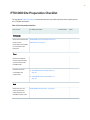
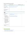
PTX1000 Site Preparaon Checklist | 39
PTX1000 Site Guidelines and Requirements | 41
PTX1000 Environmental Requirements and Specicaons | 41
General Site Guidelines | 42
PTX1000 Chassis Grounding Cable and Lug Specicaons | 43
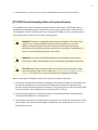
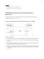
PTX1000 Clearance Requirements for Airow and Hardware Maintenance | 44
PTX1000 Physical Specicaons | 45
Site Electrical Wiring Guidelines | 45
PTX1000 Rack Requirements | 46
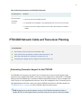
PTX1000 Network Cable and Transceiver Planning | 48
Determining Transceiver Support for the PTX1000 | 48
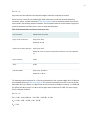
Cable and Connector Specicaons for MX and PTX Series Devices | 50
Fiber-Opc Cable Signal Loss, Aenuaon, and Dispersion | 57
Calculang Power Budget and Power Margin for Fiber-Opc Cables | 59
How to Calculate Power Budget for Fiber-Opc Cables | 59
How to Calculate Power Margin for Fiber-Opc Cables | 59
PTX1000 Management Cable Specicaons and Pinouts | 61
Cable Specicaons for Console and Management Connecons for the PTX1000 | 61
Management Port Connector Pinouts for the PTX1000 | 62
Console Port Connector Pinouts for the PTX1000 | 63
USB Port Specicaons for the PTX1000 | 64
3
Inial Installaon and Conguraon
PTX1000 Installaon Overview | 66
Overview of Installing the PTX1000 | 66
PTX1000 Installaon Safety Guidelines | 67
iv

Unpacking and Mounng the PTX1000 | 68
Unpacking the PTX1000 | 68
Mounng the PTX1000 in a Rack | 69
Before You Begin Mounng the PTX1000 | 70
Mounng the PTX1000 | 71
Connecng the PTX1000 to Power | 73
Connecng the PTX1000 to Ground | 73
Connecng AC Power to the PTX1000 | 75
Connecng DC Power to the PTX1000 | 78
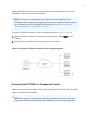
Connecng the PTX1000 to External Devices | 83
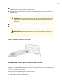
Connecng the PTX1000 to a Management Ethernet Device | 83
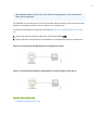
Connecng the PTX1000 to a Management Console | 84
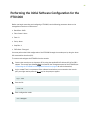
Performing the Inial Soware Conguraon for the PTX1000 | 86
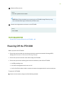
Powering O the PTX1000 | 88
4
Maintaining Components
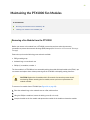
Maintaining the PTX1000 Fan Modules | 92
Removing a Fan Module from the PTX1000 | 92
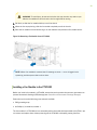
Installing a Fan Module in the PTX1000 | 93
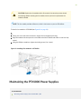
Maintaining the PTX1000 Power Supplies | 94
Removing a Power Supply from the PTX1000 | 95
Installing a Power Supply in a PTX1000 | 96
Maintaining the PTX1000 Transceivers and Fiber-Opc Cables | 98
Removing a Transceiver from the PTX1000 | 98
Installing a Transceiver in the PTX1000 | 100
Disconnecng a Fiber-Opc Cable from the PTX1000 | 101
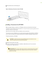
Connecng a Fiber-Opc Cable to the PTX1000 | 102
Maintaining Fiber-Opc Cables in a PTX1000 | 103
v

Uninstalling the PTX1000 | 104
5
Troubleshoong Hardware
Troubleshoong the PTX1000 | 107
PTX1000 Troubleshoong Resources Overview | 107
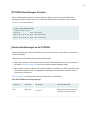
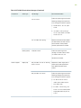
PTX1000 Alarm Messages Overview | 108
Chassis Alarm Messages on the PTX1000 | 108
6
Returning the Chassis or Components
Returning the PTX1000 Chassis or Components | 114
Locang the Serial Number on a PTX1000 Chassis or Component | 114
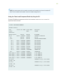
Lisng the Chassis and Component Details by Using the CLI | 115
Locang the Chassis Serial Number ID Label on a PTX1000 | 116
Locang the Serial Number ID Labels on FRU Components | 116
Contact Customer Support to Obtain Return Material Authorizaon | 116
Packing a PTX1000 Chassis or Component for Shipping | 117
Packing a PTX1000 for Shipping | 118
Packing PTX1000 Components for Shipping | 118
7
Safety and Compliance Informaon
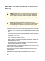
PTX1000 General Electrical Safety Guidelines and Warnings | 121
Denions of Safety Warning Levels | 122
Qualied Personnel Warning | 124
Warning Statement for Norway and Sweden | 124
Fire Safety Requirements | 125
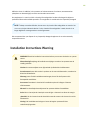
Installaon Instrucons Warning | 126
Chassis and Component Liing Guidelines | 127
Restricted Access Warning | 127
Ramp Warning | 129
Rack-Mounng and Cabinet-Mounng Warnings | 129
vi

Grounded Equipment Warning | 133
Radiaon from Open Port Apertures Warning | 134
Laser and LED Safety Guidelines and Warnings | 135
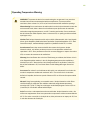
Maintenance and Operaonal Safety Guidelines and Warnings | 138
Acon to Take Aer an Electrical Accident | 144
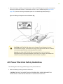
Prevenon of Electrostac Discharge Damage | 144
AC Power Electrical Safety Guidelines | 145
AC Power Disconnecon Warning | 146
PTX1000 DC Power Electrical Safety Guidelines | 147
DC Power Copper Conductors Warning | 148
DC Power Disconnecon Warning | 148
DC Power Grounding Requirements and Warning | 150
DC Power Wiring Sequence Warning | 151
DC Power Wiring Terminaons Warning | 152
Mulple Power Supplies Disconnecon Warning | 154
TN Power Warning | 154
PTX1000 Agency Approvals and Compliance Statements | 155
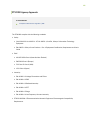
PTX1000 Agency Approvals | 156
Compliance Statements for EMC Requirements | 157
Compliance Statements for Environmental Requirements | 158
PTX1000 Compliance Statements for Acousc Noise | 158
PTX1000 Compliance Statements for Acousc Noise | 159
vii

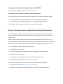
About This Guide
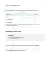
Use this guide to install hardware and perform inial soware conguraon, roune maintenance, and
troubleshoong for the PTX1000 Packet Transport Router.
Aer compleng the installaon and basic conguraon procedures covered in this guide, refer to the
Junos OS documentaon for informaon about further soware conguraon.
RELATED DOCUMENTATION
PTX1000 Quick Start
viii


PTX1000 System Overview
IN THIS SECTION
PTX1000 Packet Transport Router Descripon | 2
PTX1000 Hardware Component Overview | 6
PTX1000 Component Redundancy | 7
PTX1000 Field-Replaceable Units | 7
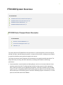
PTX1000 Packet Transport Router Descripon
IN THIS SECTION
Benets of the PTX1000 Router | 3
Port Panel and Management Panel | 4
FRU Panel | 5
The Juniper Networks PTX1000 Packet Transport Router is a xed-conguraon router that supports
10-Gbps, 40-Gbps, and 100-Gbps port speeds in a compact 2U form factor, enabling service providers
to organically distribute peering points throughout the network.
The system architecture cleanly separates control operaons from packet forwarding operaons. This
design eliminates processing and trac bolenecks, perming the PTX1000 to achieve high
performance.
• Control operaons are performed by the Roung Engine, which runs the Juniper Networks Junos
operang system (Junos OS). The Roung Engine handles roung protocols, trac engineering,
policy, policing, monitoring, and conguraon management. Junos OS is installed on the PTX1000
router’s internal 2 x 64-gigabyte (GB) M.2 SATA solid-state drives (SSDs). The 64-GB SSDs have 50
GB of usable space—the remaining space is reserved. The Roung Engine is enhanced by a 2.5-GHz
quad core Intel CPU and 32 GB of SDRAM.
2

NOTE: The 2 x 64-GB SSDs installed in the PTX1000 support the request vmhost snapshot
command, which creates a recovery snapshot of the currently running and acve le system
parons, and request vmhost snapshot recovery command, which recovers the primary disk from
the snapshot content stored in the backup disk. In addion, the 64-GB SSDs support
enhanced hardware resiliency through storage paroning and redundancy.
Earlier versions of the PTX1000 have 2 x 32-GB M.2 SATA SSDs. PTX1000 routers with 32-
GB SSDs do not support the request vmhost snapshot and request vmhost snapshot recovery
commands, and do not support enhanced hardware resiliency. To determine the size of the
SSDs installed in your device, issue the show vmhost hardware CLI command. The capacity of Disk1
and Disk2 is displayed in the output as 32.0 GB if 32-GB SSDs are installed, and the capacity is
displayed as 50.0 GB if 64-GB SSDs are installed. See the Junos OS Soware Installaon and
Upgrade Guide for more informaon.
• Forwarding operaons are performed by the Packet Forwarding Engines, which include ASICs
designed by Juniper Networks. The custom ExpressPlus ASICs enable the PTX1000 to provide up to
2.88 terabits per second (Tbps) of forwarding capacity. The ExpressPlus ASICs are connected to
Hybrid Memory Cubes (HMCs). These high-eciency memory modules provide packet buering,
virtual output queue (VOQ) memory, and improved logical system scale.
TIP: For informaon about features supported on PTX Series routers, see Feature Explorer.
Benets of the PTX1000 Router
• Increased scalability—The PTX1000 scales to 3 Tbps in a single chassis, supporng up to 288 10-
Gigabit Ethernet interfaces, 72 40-Gigabit Ethernet interfaces, and 24 100-Gigabit Ethernet
interfaces, giving service providers the performance and scalability needed as networks grow. The
purpose-built ASICs in the PTX1000 provide enhanced packet processing for both full IP
funconality and MPLS transport, accommodang scale as trac connues to increase and
opmizing IP/MPLS transit funconality.
• Space eciency—Providing high capacity in a compact 2U form-factor, the PTX1000 meets
installaon needs for peering Internet exchange points, peering collocaons, central oces, and
regional networks, especially in emerging markets.
• Always-on infrastructure base—The PTX1000 is engineered with full hardware redundancy for
cooling, power supplies, and forwarding, allowing service providers to meet stringent service-level
agreements across the core.
3

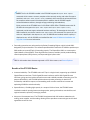
Port Panel and Management Panel
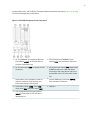
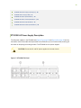
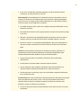
The port panel of the PTX1000 contains 72 network ports and port LEDs. The management panel of the
PTX1000 contains console and management ports, a reset buon, system status LEDs, clocking ports,
and a USB port. Figure 1 on page 4 shows the PTX1000 port panel and management panel.
Figure 1: PTX1000 Port Panel and Management Panel
1—Port panel 2—Management panel
Each of the 72 network ports on the port panel supports quad small form-factor pluggable plus (QSFP+)
transceivers, and is congured as a channelized 4 x 10-Gigabit Ethernet interface by default (for a
maximum of 288 10-Gigabit Ethernet ports). You can congure each of the 72 ports as a 40-Gigabit
Ethernet interface. You can also congure 24 of the 72 network ports as 100-Gigabit Ethernet
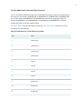
interfaces. Table 1 on page 4 describes the maximum number of ports for each interface type
supported by the PTX1000.
Table 1: Maximum Supported Ports at Each Interface Speed
Interface Type Maximum Supported Ports
10-Gigabit Ethernet 288
40-Gigabit Ethernet 72
100-Gigabit Ethernet 24
4

NOTE: You can purchase a licensed model of the PTX1000 that allows you to use 18 of the 72
network ports. You can use 18 ports in any combinaon, for a maximum of 72 10-Gigabit
Ethernet interfaces, 18 40-Gigabit Ethernet interfaces, or 6 100-Gigabit Ethernet interfaces. You
can purchase addional licenses to enable the remaining network ports. Each license enables an
addional 18 of the 72 total network ports.
You manage the PTX1000 by using the Junos OS CLI, which is accessible through the console and out-
of-band management ports on the management panel. In addion, the management panel has system
status LEDs that alert you to minor or major alarms or other issues with the router, external clock
synchronizaon ports, and a USB port to support soware installaon and recovery.
For more informaon about the port and management panels, see "PTX1000 Port Panel " on page 9
and "PTX1000 Management Panel" on page 19.
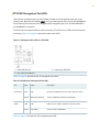
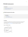
FRU Panel
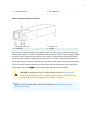
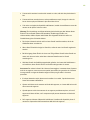
The eld-replaceable unit (FRU) panel of the PTX1000 contains the fan modules and power supplies for
the PTX1000. Figure 2 on page 5 shows the PTX1000 FRU panel.
Figure 2: PTX1000 FRU Panel
1—Power supplies (4) 3—ESD point
2—Fan modules (3)
The cooling system in a PTX1000 consists of three 80-W fan modules that operate at 150 cubic feet per
minute (CFM) at full speed as well as fans housed in the power supplies. Each fan module has dual
counter-rotang fans. These fan modules can be hot-swapped—you do not need to power o the router
or disrupt roung funcon to replace a fan module.
In the PTX1000 cooling system, cool air enters through the vents in the port panel and hot air exhausts
through the FRU panel. This type of airow is known as
airow out
or
port-to-FRU airow
.
5

The PTX1000 has four 1600-W power supplies, either AC or DC depending on your conguraon. Each
power supply provides 12-VDC output with a standby voltage of 12 VDC. The power supplies can be
hot-swapped—you do not need to power o the router or disrupt roung funcon to replace a power
supply
For more informaon about the components on the FRU panel, see "PTX1000 Cooling System
Descripon" on page 24, "PTX1000 AC Power Supply Descripon" on page 28, and "PTX1000 DC
Power Supply Descripon" on page 30.
SEE ALSO
request vmhost snapshot
show vmhost hardware
PTX1000 Hardware Component Overview
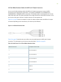
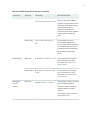
The PTX1000 supports the components in Table 2 on page 6 listed in alphabec order. See "PTX1000
Physical Specicaons" on page 45 for the dimensions and weight of the PTX1000.
Table 2: PTX1000 Hardware Components
Component Spare Juniper Model Number CLI Output Descripon
Chassis PTX1000-72Q-CHAS-S PTX1000 "PTX1000 Packet Transport Router
Descripon" on page 2
Fan module PTX1000-FAN-S PTX1000 Fan Tray "PTX1000 Cooling System
Descripon" on page 24
Power supplies JPSU-1600W-AC-AFO AC AFO 1600W PSU "PTX1000 AC Power Supply
Descripon" on page 28
JPSU-1600W-DC-AFO DC AFO 1600W PSU "PTX1000 DC Power Supply
Descripon" on page 30
6

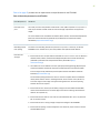
PTX1000 Component Redundancy
The following hardware components provide redundancy on PTX1000 models:
• Cooling system—The PTX1000 has three fan modules. Each fan module is a redundant unit
containing two fans. If a fan module fails and the remaining fan modules are unable to keep the
PTX1000 within the desired temperature thresholds, chassis alarms are raised and the PTX1000
might shut down.
• Power supplies—The PTX1000 is shipped with four power supplies. A PTX1000 provides for twice
the number of power supplies needed to power all the components in the router, which is known as
2N redundancy
. If one power supply fails or is removed, the remaining power supplies balance the
electrical load without interrupon and sll provide
N
+ 1 redundancy while the failing power supply
is replaced.
For power feed redundancy, connect power source feed A to power supplies 0 and 1 and connect
power source feed B to power supplies 2 and 3. A single feed can provide power to all components
in the PTX1000.
CAUTION: Do not connect feed A and feed B to the same power supply input
terminal.
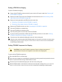
PTX1000 Field-Replaceable Units
Field-replaceable units (FRUs) are components that you can replace at your site. The PTX1000 FRUs are
hot-removable and hot-insertable—you can remove and replace them without powering o the
PTX1000 or disrupng the roung funcon.
CAUTION: Replace a failed fan module with a new fan module within 30 seconds of
removal to prevent chassis overheang.
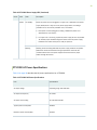
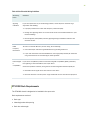
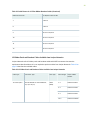
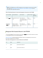
Table 3 on page 8 lists the FRUs for the PTX1000 and acons to take before removing them.
7

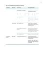
Table 3: Required Acons Before Removing a FRU from the PTX1000
FRU Required Acons Before Removal
Power supplies (4) Remove the power cord or cable for the power supply unit.
NOTE: You need a minimum of two powered power supplies for the PTX1000 to operate
properly.
Fan modules (3) None.
Opcal transceivers None. We recommend that you disable the interface by using the set interfaces
interface-
name
disable command before you remove the transceiver. See "Disconnecng a Fiber-
Opc Cable from the PTX1000" on page 101.
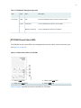
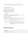
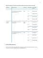
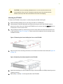
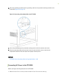
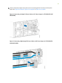
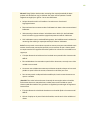
See Figure 3 on page 8 for the locaon of the power supplies and fan modules on the FRU panel of
the PTX1000.
Figure 3: FRUs on the FRU Panel in a PTX1000
1—Power supplies (4) 2—Fan modules (3)
NOTE: If you have a Juniper Care service contract, register any addion, change, or upgrade of
hardware components at hps://www.juniper.net/customers/support/tools/updateinstallbase/ .
Failure to do so can result in signicant delays if you need replacement parts. This note does not
apply if you replace exisng components with the same type of component.
8

PTX1000 Port Panel
IN THIS SECTION
PTX1000 Port Panel | 9
PTX1000 Network Port LEDs | 17
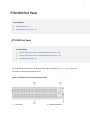
PTX1000 Port Panel
IN THIS SECTION
Example: Using Network Ports as 40-Gigabit Ethernet Interfaces | 10
Example: Using Network Ports as 100-Gigabit Ethernet Interfaces | 11
PTX1000 Port Mapping | 12
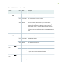
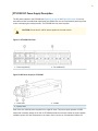
The PTX1000 supports 10-Gbps, 40-Gbps, and 100-Gbps port speeds. Figure 4 on page 9 shows the
PTX1000 port panel and management panel.
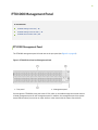
Figure 4: PTX1000 Port Panel and Management Panel
1—Port panel 2—Management panel
9

Each of the 72 network ports on the port panel supports quad small form-factor pluggable plus (QSFP+)
transceivers. By default, the network ports operate as channelized 4 x 10-Gigabit Ethernet interfaces—
using QSFP+ to SFP+ ber breakout cables—for a maximum of 288 10-Gigabit Ethernet ports. You can
congure each of the 72 ports as a 40-Gigabit Ethernet interface, in groups of three ports—when you
congure the rst port in a port group to operate at 40 Gbps, that port and the next two ports operate
at 40 Gbps. You can also congure 24 of the 72 network ports as 100-Gigabit Ethernet interfaces. The
24 network ports that can be congured as 100-Gigabit Ethernet interfaces support QSFP28
transceivers.
NOTE: Network ports that can be congured as 100-Gigabit Ethernet interfaces are marked with
a ne black line underneath the transceiver socket. When the port is congured as a 100-Gigabit
Ethernet interface, the two adjacent ports are disabled. For example, port 1 supports 100-Gbps
port speed. When you congure the port as a 100-Gigabit Ethernet interface, port 0 and port 2
are disabled.
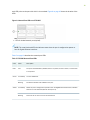
NOTE: Port speeds are congured using the set chassis fpc 0 pic 0 port
port-number
speed
speed
command. You congure ports to operate at 40 Gbps by using the 40g speed opon. You
congure ports to operate at 100 Gbps by using the 100g speed opon. If you congure a port to
operate at 40 Gbps or 100 Gbps, and you want to return the port to the default conguraon,
delete the speed statement from the conguraon at the [chassis fpc 0 pic 0 port
port-number
]
hierarchy level and commit the conguraon. The network port is reset to the default 4 x 10-
Gigabit Ethernet interface. Table 4 on page 12 shows the available combinaons for the
network ports on the PTX1000.
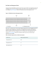
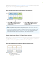
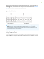
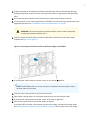
Example: Using Network Ports as 40-Gigabit Ethernet Interfaces
All network ports on the PTX1000 can be congured as 40-Gigabit Ethernet interfaces. You must
congure 40-Gigabit Ethernet interfaces in groups of three network ports. When the port speed is
congured as 40 Gbps on the rst port in a port group, all three ports in the port group operate at
40 Gbps. For example, if you congure port 0 as a 40-Gigabit Ethernet inteface, ports 1 and 2 are also 40-
10

Gigabit Ethernet interfaces (see Figure 5 on page 11). Table 4 on page 12 provides the complete list of
port groups that can be congured as 40-Gigabit Ethernet interfaces.
Figure 5: 40-Gigabit Ethernet Interface Conguraon Uses Three Network Ports
1—When port 0 is congured to operate at
40 Gbps, ports 1 and 2 also operate at
40 Gbps (in blue).
2—When port 3 is congured to operate at
40 Gbps, ports 4 and 5 also operate at
40 Gbps (in green).
NOTE: 40-Gigabit Ethernet interfaces are congured using the set chassis fpc 0 pic 0 port
port-
number
speed
speed
command. For example, to congure the rst set of three network ports as 40-
Gigabit Ethernet interfaces, use the set chassis fpc 0 pic 0 port 0 speed 40g command. Aer you
commit this conguraon, each of the three ports (0, 1, and 2) operate at 40 Gbps.
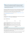
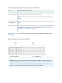
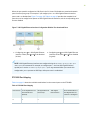
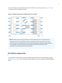
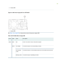
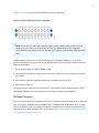
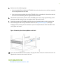
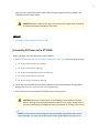
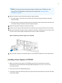
Example: Using Network Ports as 100-Gigabit Ethernet Interfaces
Starng with port 1, every second and sixth port in each group of six network ports can be congured as
100-Gigabit Ethernet interfaces. Figure 6 on page 11 shows the 100-Gigabit Ethernet-capable ports in
a group of six network ports, designated by a ne black line underneath the port.
Figure 6: 100-Gigabit Ethernet Ports Indicated by a Black Line Underneath the Port
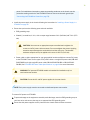
11

When the port speed is congured as 100 Gbps in the CLI, Junos OS disables two associated network
ports from that port group. For example, if you congure port 1 as a 100-Gigabit Ethernet interface,
ports 0 and 2 are disabled (see Figure 7 on page 12). Table 4 on page 12 provides the complete list of
ports that can be congured to operate as 100-Gigabit Ethernet interfaces, and the corresponding ports
that are disabled.
Figure 7: 100-Gigabit Ethernet Interface Conguraon Disables Two Associated Ports
1—Conguring port 1 as a 100-Gigabit Ethernet
interface causes ports 0 and 2 to be disabled
(in blue).
2—Conguring port 5 as a 100-Gigabit Ethernet
interface causes ports 3 and 4 to be disabled
(in green).
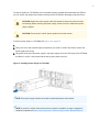
NOTE: 100-Gigabit Ethernet interfaces are congured using the set chassis fpc 0 pic 0 port
port-
number
speed
speed
command. For example, to congure port 1—the rst 100-Gigabit Ethernet-
capable port—use the set chassis fpc 0 pic 0 port 1 speed 100g command. Aer you commit this
conguraon, port 1 operates at 100 Gbps, while ports 0 and 2 are disabled.
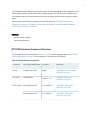
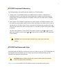
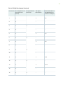
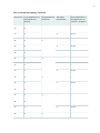
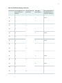
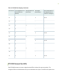
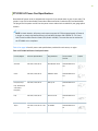
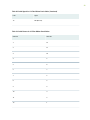
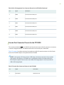
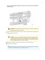
PTX1000 Port Mapping
Table 4 on page 12 shows the available combinaons for the network ports on the PTX1000.
Table 4: PTX1000 Port Mapping
Port Number 4 x 10-Gigabit Ethernet
Channelized Ports
(Default)
40-Gigabit Ethernet
Port Groups
100-Gigabit
Ethernet Ports
Ports Disabled When a
100-Gigabit Ethernet
Interface Is Congured
0✓ ✓ – –
12
La pagina si sta caricando...
La pagina si sta caricando...
La pagina si sta caricando...
La pagina si sta caricando...
La pagina si sta caricando...
La pagina si sta caricando...
La pagina si sta caricando...
La pagina si sta caricando...
La pagina si sta caricando...
La pagina si sta caricando...
La pagina si sta caricando...
La pagina si sta caricando...
La pagina si sta caricando...
La pagina si sta caricando...
La pagina si sta caricando...
La pagina si sta caricando...
La pagina si sta caricando...
La pagina si sta caricando...
La pagina si sta caricando...
La pagina si sta caricando...
La pagina si sta caricando...
La pagina si sta caricando...
La pagina si sta caricando...
La pagina si sta caricando...
La pagina si sta caricando...
La pagina si sta caricando...
La pagina si sta caricando...
La pagina si sta caricando...
La pagina si sta caricando...
La pagina si sta caricando...
La pagina si sta caricando...
La pagina si sta caricando...
La pagina si sta caricando...
La pagina si sta caricando...
La pagina si sta caricando...
La pagina si sta caricando...
La pagina si sta caricando...
La pagina si sta caricando...
La pagina si sta caricando...
La pagina si sta caricando...
La pagina si sta caricando...
La pagina si sta caricando...
La pagina si sta caricando...
La pagina si sta caricando...
La pagina si sta caricando...
La pagina si sta caricando...
La pagina si sta caricando...
La pagina si sta caricando...
La pagina si sta caricando...
La pagina si sta caricando...
La pagina si sta caricando...
La pagina si sta caricando...
La pagina si sta caricando...
La pagina si sta caricando...
La pagina si sta caricando...
La pagina si sta caricando...
La pagina si sta caricando...
La pagina si sta caricando...
La pagina si sta caricando...
La pagina si sta caricando...
La pagina si sta caricando...
La pagina si sta caricando...
La pagina si sta caricando...
La pagina si sta caricando...
La pagina si sta caricando...
La pagina si sta caricando...
La pagina si sta caricando...
La pagina si sta caricando...
La pagina si sta caricando...
La pagina si sta caricando...
La pagina si sta caricando...
La pagina si sta caricando...
La pagina si sta caricando...
La pagina si sta caricando...
La pagina si sta caricando...
La pagina si sta caricando...
La pagina si sta caricando...
La pagina si sta caricando...
La pagina si sta caricando...
La pagina si sta caricando...
La pagina si sta caricando...
La pagina si sta caricando...
La pagina si sta caricando...
La pagina si sta caricando...
La pagina si sta caricando...
La pagina si sta caricando...
La pagina si sta caricando...
La pagina si sta caricando...
La pagina si sta caricando...
La pagina si sta caricando...
La pagina si sta caricando...
La pagina si sta caricando...
La pagina si sta caricando...
La pagina si sta caricando...
La pagina si sta caricando...
La pagina si sta caricando...
La pagina si sta caricando...
La pagina si sta caricando...
La pagina si sta caricando...
La pagina si sta caricando...
La pagina si sta caricando...
La pagina si sta caricando...
La pagina si sta caricando...
La pagina si sta caricando...
La pagina si sta caricando...
La pagina si sta caricando...
La pagina si sta caricando...
La pagina si sta caricando...
La pagina si sta caricando...
La pagina si sta caricando...
La pagina si sta caricando...
La pagina si sta caricando...
La pagina si sta caricando...
La pagina si sta caricando...
La pagina si sta caricando...
La pagina si sta caricando...
La pagina si sta caricando...
La pagina si sta caricando...
La pagina si sta caricando...
La pagina si sta caricando...
La pagina si sta caricando...
La pagina si sta caricando...
La pagina si sta caricando...
La pagina si sta caricando...
La pagina si sta caricando...
La pagina si sta caricando...
La pagina si sta caricando...
La pagina si sta caricando...
La pagina si sta caricando...
La pagina si sta caricando...
La pagina si sta caricando...
La pagina si sta caricando...
La pagina si sta caricando...
La pagina si sta caricando...
La pagina si sta caricando...
La pagina si sta caricando...
La pagina si sta caricando...
La pagina si sta caricando...
La pagina si sta caricando...
La pagina si sta caricando...
La pagina si sta caricando...
La pagina si sta caricando...
La pagina si sta caricando...
La pagina si sta caricando...
La pagina si sta caricando...
La pagina si sta caricando...
La pagina si sta caricando...
-
 1
1
-
 2
2
-
 3
3
-
 4
4
-
 5
5
-
 6
6
-
 7
7
-
 8
8
-
 9
9
-
 10
10
-
 11
11
-
 12
12
-
 13
13
-
 14
14
-
 15
15
-
 16
16
-
 17
17
-
 18
18
-
 19
19
-
 20
20
-
 21
21
-
 22
22
-
 23
23
-
 24
24
-
 25
25
-
 26
26
-
 27
27
-
 28
28
-
 29
29
-
 30
30
-
 31
31
-
 32
32
-
 33
33
-
 34
34
-
 35
35
-
 36
36
-
 37
37
-
 38
38
-
 39
39
-
 40
40
-
 41
41
-
 42
42
-
 43
43
-
 44
44
-
 45
45
-
 46
46
-
 47
47
-
 48
48
-
 49
49
-
 50
50
-
 51
51
-
 52
52
-
 53
53
-
 54
54
-
 55
55
-
 56
56
-
 57
57
-
 58
58
-
 59
59
-
 60
60
-
 61
61
-
 62
62
-
 63
63
-
 64
64
-
 65
65
-
 66
66
-
 67
67
-
 68
68
-
 69
69
-
 70
70
-
 71
71
-
 72
72
-
 73
73
-
 74
74
-
 75
75
-
 76
76
-
 77
77
-
 78
78
-
 79
79
-
 80
80
-
 81
81
-
 82
82
-
 83
83
-
 84
84
-
 85
85
-
 86
86
-
 87
87
-
 88
88
-
 89
89
-
 90
90
-
 91
91
-
 92
92
-
 93
93
-
 94
94
-
 95
95
-
 96
96
-
 97
97
-
 98
98
-
 99
99
-
 100
100
-
 101
101
-
 102
102
-
 103
103
-
 104
104
-
 105
105
-
 106
106
-
 107
107
-
 108
108
-
 109
109
-
 110
110
-
 111
111
-
 112
112
-
 113
113
-
 114
114
-
 115
115
-
 116
116
-
 117
117
-
 118
118
-
 119
119
-
 120
120
-
 121
121
-
 122
122
-
 123
123
-
 124
124
-
 125
125
-
 126
126
-
 127
127
-
 128
128
-
 129
129
-
 130
130
-
 131
131
-
 132
132
-
 133
133
-
 134
134
-
 135
135
-
 136
136
-
 137
137
-
 138
138
-
 139
139
-
 140
140
-
 141
141
-
 142
142
-
 143
143
-
 144
144
-
 145
145
-
 146
146
-
 147
147
-
 148
148
-
 149
149
-
 150
150
-
 151
151
-
 152
152
-
 153
153
-
 154
154
-
 155
155
-
 156
156
-
 157
157
-
 158
158
-
 159
159
-
 160
160
-
 161
161
-
 162
162
-
 163
163
-
 164
164
-
 165
165
-
 166
166
-
 167
167


in altre lingue
- English: Juniper PTX1000
Documenti correlati
-
Juniper PTX1000 Manuale utente
-
Juniper MX10003 Hardware Guide
-
-
-
-
-
-
-
-
Juniper MX204 Manuale utente