
MX10003 Universal Routing Platform
Hardware Guide
Published
2020-07-17

Juniper Networks, Inc.
1133 Innovation Way
Sunnyvale, California 94089
USA
408-745-2000
www.juniper.net
Juniper Networks, the Juniper Networks logo, Juniper, and Junos are registered trademarks of Juniper Networks, Inc. in
the United States and other countries. All other trademarks, service marks, registered marks, or registered service marks
are the property of their respective owners.
Juniper Networks assumes no responsibility for any inaccuracies in this document. Juniper Networks reserves the right
to change, modify, transfer, or otherwise revise this publication without notice.
MX10003 Universal Routing Platform Hardware Guide
Copyright © 2020 Juniper Networks, Inc. All rights reserved.
The information in this document is current as of the date on the title page.
YEAR 2000 NOTICE
Juniper Networks hardware and software products are Year 2000 compliant. Junos OS has no known time-related
limitations through the year 2038. However, the NTP application is known to have some difficulty in the year 2036.
END USER LICENSE AGREEMENT
The Juniper Networks product that is the subject of this technical documentation consists of (or is intended for use with)
Juniper Networks software. Use of such software is subject to the terms and conditions of the End User License Agreement
(“EULA”) posted at https://support.juniper.net/support/eula/. By downloading, installing or using such software, you
agree to the terms and conditions of that EULA.
ii

Table of Contents
About the Documentation | xi
Documentation and Release Notes | xi
Using the Examples in This Manual | xi
Merging a Full Example | xii
Merging a Snippet | xiii
Documentation Conventions | xiii
Documentation Feedback | xvi
Requesting Technical Support | xvi
Self-Help Online Tools and Resources | xvii
Creating a Service Request with JTAC | xvii
Overview
1
MX10003 System Overview | 19
Benefits of the MX10003 Router | 19
MX10003 Router Hardware Overview | 20
MX10003 Hardware Components and CLI Terminology | 21
MX10003 Component Redundancy | 23
MX10003 Field-Replaceable Units | 24
MX10003 Chassis | 25
MX10003 Chassis Description | 25
MX10003 Front and Rear Panel Components | 27
Front Panel Components | 28
Rear Panel Components | 28
MX10003 Cable Management Bracket Description | 28
Alarm LEDs on the MX10003 Front Panel | 29
MX10003 Cooling System | 30
MX10003 Cooling System Description | 31
Fan Modules | 31
Airflow | 33
Air Filter Unit | 33
iii

Power Supply Cooling System | 34
MX10003 Fan Module LED | 34
MX10003 AC Power System | 35
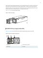
MX10003 AC Power System Description | 35
MX10003 AC Power Supply Module LEDs | 36
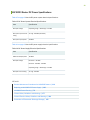
MX10003 Router AC Power Specifications | 37
AC Power Circuit Breaker Requirements for the MX10003 Router | 38
AC Power Cord Specifications for MX10003 Routers | 39
MX10003 DC Power System | 41
MX10003 DC Power System Description | 41
MX10003 DC Power Supply Module LEDs | 42
MX10003 Router DC Power Specifications | 43
DC Power Circuit Breaker Requirements for the MX10003 Router | 44
DC Power Source Cabling for MX10003 Router | 44
DC Power Cable Specifications for MX10003 Router | 45
DC Power Cable Lug Specifications | 45
DC Power Cable Specifications | 46
MX10003 Routing and Control Board | 47
MX10003 Routing and Control Board (RCB) Description | 47
Routing and Control Board Functions | 48
Routing and Control Board Components | 48
RCB Front Panel | 48
RCB Interface Ports | 50
MX10003 RCB LEDs | 51
MX10003 Interface Modules | 53
MX10003 MPC (Multi-Rate) | 53
MX10003 Port and Interface Numbering | 55
MX10003 MPC (Multi-Rate) LEDs | 56
Multi-Rate Ethernet MIC LEDs | 57
iv

Site Planning, Preparation, and Specifications
2
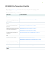
MX10003 Site Preparation Checklist | 59
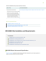
MX10003 Site Guidelines and Requirements | 60
MX10003 Router Environmental Specifications | 60
MX10003 Router Grounding Specifications | 61
Grounding Points Specifications | 61
Grounding Cable Lug Specifications | 62
Grounding Cable Specifications | 63
MX10003 Router Clearance Requirements for Airflow and Hardware Maintenance | 63
MX10003 Router Physical Specifications | 64
MX10003 Router Rack Requirements | 66
MX10003 Router Cabinet Requirements and Specifications | 68
MX10003 Power Planning | 70
Calculating Power Requirements for MX10003 Router | 70
Power Requirements for MX10003 Components | 71
Calculating Power Consumption for Your Configuration | 71
Calculating System Thermal Output | 73
MX10003 Network Cable and Transceiver Planning | 74
Calculating Power Budget and Power Margin for Fiber-Optic Cables | 74
How to Calculate Power Budget for Fiber-Optic Cable | 75
How to Calculate Power Margin for Fiber-Optic Cable | 75
CB-RE and RCB Interface Cable and Wire Specifications for MX Series Routers | 77
Fiber-Optic Cable Signal Loss, Attenuation, and Dispersion | 78
Signal Loss in Multimode and Single-Mode Fiber-Optic Cable | 78
Attenuation and Dispersion in Fiber-Optic Cable | 78
MX10003 Management and Console Port Specifications and Pinouts | 79
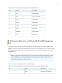
RJ-45 Connector Pinouts for MX Series CB-RE or RCB Auxillary and Console Ports | 79
RJ-45 Connector Pinouts for an MX Series CB-RE or RCB Management Port | 80
v

Initial Installation and Configuration
3
MX10003 Installation Overview | 83
Tools and Parts Required to Unpack the MX10003 Router | 84
Unpacking the MX10003 Router | 85
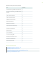
Verifying the MX10003 Router Parts Received | 86
Installing the MX10003 | 88
Tools Required to the Install MX10003 Router in a Rack | 88
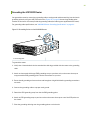
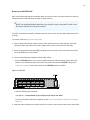
Installing the MX10003 Router in a Rack | 89
Connecting the MX10003 to Power | 92
Tools and Parts Required for MX10003 Router Grounding and Power Connections | 92
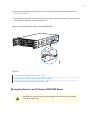
Grounding the MX10003 Router | 94
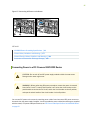
Connecting Power to an AC-Powered MX10003 Router | 95
Connecting Power to a DC-Powered MX10003 Router | 97
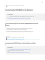
Connecting the MX10003 to the Network | 100
Tools and Parts Required to Connect the MX10003 Router to External Devices | 100
Connecting the MX10003 Router to External Devices and Cables | 100
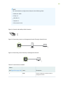
Connecting the Router to a Network for Out-of-Band Management | 101
Connecting the Router to a Console Device | 102
Connecting the Router to External Clocking and Timing Devices | 104
Powering On and Off the MX10003 | 106
Powering On an AC-Powered MX10003 Router | 107
Powering On a DC-Powered MX10003 Router | 108
Powering Off the MX10003 Router | 110
Initially Configuring the MX10003 Router | 110
vi

Maintaining Components
4
Routine Maintenance Procedures for MX10003 Routers | 116
Maintaining MX10003 Cooling System Components | 116
Maintaining the MX10003 Air Filter | 116
Replacing the MX10003 Air Filter Unit | 117
Removing the MX10003 Air Filter Unit | 118
Installing the MX10003 Air Filter Unit | 118
Replacing the MX10003 Air Filter | 119
Removing the MX10003 Air Filter | 120
Installing the MX10003 Air Filter | 121
Maintaining the MX10003 Fan Module | 122
Replacing an MX10003 Fan Module | 123
Removing an MX10003 Fan Module | 124
Installing an MX10003 Fan Module | 125
Maintaining MX10003 Power System Components | 126
Maintaining the Power Supplies | 126
Replacing an MX10003 AC Power Supply | 127
Removing an MX10003 AC Power Supply | 127
Installing an MX10003 AC Power Supply | 129
Replacing an MX10003 DC Power Supply | 130
Removing an MX10003 DC Power Supply | 130
Installing an MX10003 DC Power Supply | 132
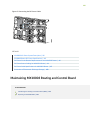
Maintaining MX10003 Routing and Control Board | 134
Maintaining the Routing and Control Board (RCB) | 135
Replacing an MX10003 RCB | 136
Removing an MX10003 RCB | 137
Installing an MX10003 RCB | 138
vii

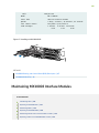
Maintaining MX10003 Interface Modules | 140
Maintaining MICs | 141
Replacing an MX10003 MIC | 141
Removing an MX10003 MIC | 142
Installing an MX10003 MIC | 144
Maintaining MPCs | 146
Replacing an MX10003 MPC | 148
Removing an MX10003 MPC | 148
Installing an MX10003 MPC | 150
Maintaining Cables That Connect to MPCs or MICs | 152
Replacing a Cable on an MX10003 MPC or MIC | 154
Removing a Cable on an MPC or MIC | 154
Installing a Cable on an MPC or MIC | 155
Replace an SFP, SFP+, or QSFP+ Transceiver | 157
Remove a Transceiver | 157
Install a Transceiver | 158
Replace a QSFP28 Transceiver | 159
Remove a QSFP28 Transceiver | 160
Install a QSFP28 Transceiver | 161
Contacting Customer Support and Returning the Chassis or Components
5
Contacting Customer Support and Returning the Chassis or Components | 164
Contact Customer Support to Obtain Return Material Authorization | 164
Locating the Serial Number on a MX10003 Router or Component | 165
Listing the Chassis and Component Details Using the CLI | 166
Locating the Chassis Serial Number ID Label on a MX10003 | 166
Locating the Serial Number ID Labels on MX10003 Power Supplies | 167
Locating the Serial Number ID Label on MX10003 Fan Module | 168
Locating the Serial Number ID Labels on MX10003 Line Cards | 168
Locating the Serial Number ID Labels on MX10003 Routing and Control Board (RCB) | 169
Locating the Serial Number ID Label on a MX10003 SATA SSD | 170
Guidelines for Packing Hardware Components for Shipment | 170
viii

Safety and Compliance Information
6
Definitions of Safety Warning Levels | 174
General Safety Guidelines and Warnings | 177
General Safety Warnings for Juniper Networks Devices | 178
Qualified Personnel Warning | 179
Restricted-Access Area Warning | 180
Prevention of Electrostatic Discharge Damage | 182
Fire Safety Requirements | 184
Fire Suppression | 184
Fire Suppression Equipment | 184
Installation Instructions Warning | 185
Chassis and Component Lifting Guidelines | 186
Ramp Warning | 187
Rack-Mounting and Cabinet-Mounting Warnings | 187
Laser and LED Safety Guidelines and Warnings | 192
General Laser Safety Guidelines | 193
Class 1 Laser Product Warning | 194
Class 1 LED Product Warning | 195
Laser Beam Warning | 196
Radiation from Open Port Apertures Warning | 197
Maintenance and Operational Safety Guidelines and Warnings | 198
Battery Handling Warning | 199
Jewelry Removal Warning | 200
Lightning Activity Warning | 202
Operating Temperature Warning | 203
Product Disposal Warning | 205
General Electrical Safety Guidelines and Warnings | 206
ix

Prevention of Electrostatic Discharge Damage | 207
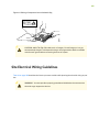
Site Electrical Wiring Guidelines | 208
AC Power Electrical Safety Guidelines | 209
AC Power Disconnection Warning | 211
DC Power Disconnection Warning | 212
DC Power Grounding Requirements and Warning | 214
DC Power Wiring Sequence Warning | 216
DC Power Wiring Terminations Warning | 219
Multiple Power Supplies Disconnection Warning | 222
TN Power Warning | 223
Action to Take After an Electrical Accident | 223
Agency Approvals for MX10003 Router | 224
Compliance Statements for NEBS | 225
Compliance Statements for EMC Requirements | 225
Canada | 226
European Community | 226
Israel | 226
Japan | 226
United States | 227
Compliance Statements for Environmental Requirements | 227
Compliance Statements for Acoustic Noise for MX10003 Router | 227
Statements of Volatility for Juniper Network Devices | 228
x

About the Documentation
IN THIS SECTION
Documentation and Release Notes | xi
Using the Examples in This Manual | xi
Documentation Conventions | xiii
Documentation Feedback | xvi
Requesting Technical Support | xvi
Use this guide to install hardware and perform initial software configuration, routine maintenance, and
troubleshooting for the MX10003 Universal Routing Platform. After completing the installation and basic
configuration procedures covered in this guide, refer to the Junos OS documentation for information about
further software configuration.
Documentation and Release Notes
To obtain the most current version of all Juniper Networks
®
technical documentation, see the product
documentation page on the Juniper Networks website at https://www.juniper.net/documentation/.
If the information in the latest release notes differs from the information in the documentation, follow the
product Release Notes.
Juniper Networks Books publishes books by Juniper Networks engineers and subject matter experts.
These books go beyond the technical documentation to explore the nuances of network architecture,
deployment, and administration. The current list can be viewed at https://www.juniper.net/books.
Using the Examples in This Manual
If you want to use the examples in this manual, you can use the load merge or the load merge relative
command. These commands cause the software to merge the incoming configuration into the current
candidate configuration. The example does not become active until you commit the candidate configuration.
xi

If the example configuration contains the top level of the hierarchy (or multiple hierarchies), the example
is a full example. In this case, use the load merge command.
If the example configuration does not start at the top level of the hierarchy, the example is a snippet. In
this case, use the load merge relative command. These procedures are described in the following sections.
Merging a Full Example
To merge a full example, follow these steps:
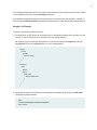
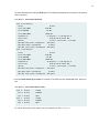
1. From the HTML or PDF version of the manual, copy a configuration example into a text file, save the
file with a name, and copy the file to a directory on your routing platform.
For example, copy the following configuration to a file and name the file ex-script.conf. Copy the
ex-script.conf file to the /var/tmp directory on your routing platform.
system {
scripts {
commit {
file ex-script.xsl;
}
}
}
interfaces {
fxp0 {
disable;
unit 0 {
family inet {
address 10.0.0.1/24;
}
}
}
}
2. Merge the contents of the file into your routing platform configuration by issuing the load merge
configuration mode command:
[edit]
user@host# load merge /var/tmp/ex-script.conf
load complete
xii

Merging a Snippet
To merge a snippet, follow these steps:
1. From the HTML or PDF version of the manual, copy a configuration snippet into a text file, save the
file with a name, and copy the file to a directory on your routing platform.
For example, copy the following snippet to a file and name the file ex-script-snippet.conf. Copy the
ex-script-snippet.conf file to the /var/tmp directory on your routing platform.
commit {
file ex-script-snippet.xsl; }
2. Move to the hierarchy level that is relevant for this snippet by issuing the following configuration mode
command:
[edit]
user@host# edit system scripts
[edit system scripts]
3. Merge the contents of the file into your routing platform configuration by issuing the load merge
relative configuration mode command:
[edit system scripts]
user@host# load merge relative /var/tmp/ex-script-snippet.conf
load complete
For more information about the load command, see CLI Explorer.
Documentation Conventions
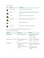
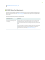
Table 1 on page xiv defines notice icons used in this guide.
xiii

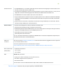
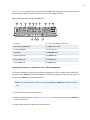
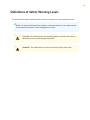
Table 1: Notice Icons
DescriptionMeaningIcon
Indicates important features or instructions.Informational note
Indicates a situation that might result in loss of data or hardware
damage.
Caution
Alerts you to the risk of personal injury or death.Warning
Alerts you to the risk of personal injury from a laser.Laser warning
Indicates helpful information.Tip
Alerts you to a recommended use or implementation.Best practice
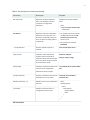
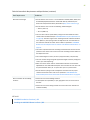
Table 2 on page xiv defines the text and syntax conventions used in this guide.
Table 2: Text and Syntax Conventions
ExamplesDescriptionConvention
To enter configuration mode, type
the configure command:
user@host> configure
Represents text that you type.Bold text like this
user@host> show chassis alarms
No alarms currently active
Represents output that appears on
the terminal screen.
Fixed-width text like this
•
A policy term is a named structure
that defines match conditions and
actions.
•
Junos OS CLI User Guide
•
RFC 1997, BGP Communities
Attribute
•
Introduces or emphasizes important
new terms.
•
Identifies guide names.
•
Identifies RFC and Internet draft
titles.
Italic text like this
xiv

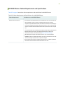
Table 2: Text and Syntax Conventions (continued)
ExamplesDescriptionConvention
Configure the machine’s domain
name:
[edit]
root@# set system domain-name
domain-name
Represents variables (options for
which you substitute a value) in
commands or configuration
statements.
Italic text like this
•
To configure a stub area, include
the stub statement at the [edit
protocols ospf area area-id]
hierarchy level.
•
The console port is labeled
CONSOLE.
Represents names of configuration
statements, commands, files, and
directories; configuration hierarchy
levels; or labels on routing platform
components.
Text like this
stub <default-metric metric>;Encloses optional keywords or
variables.
< > (angle brackets)
broadcast | multicast
(string1 | string2 | string3)
Indicates a choice between the
mutually exclusive keywords or
variables on either side of the symbol.
The set of choices is often enclosed
in parentheses for clarity.
| (pipe symbol)
rsvp { # Required for dynamic MPLS
only
Indicates a comment specified on the
same line as the configuration
statement to which it applies.
# (pound sign)
community name members [
community-ids ]
Encloses a variable for which you can
substitute one or more values.
[ ] (square brackets)
[edit]
routing-options {
static {
route default {
nexthop address;
retain;
}
}
}
Identifies a level in the configuration
hierarchy.
Indention and braces ( { } )
Identifies a leaf statement at a
configuration hierarchy level.
; (semicolon)
GUI Conventions
xv

Table 2: Text and Syntax Conventions (continued)
ExamplesDescriptionConvention
•
In the Logical Interfaces box, select
All Interfaces.
•
To cancel the configuration, click
Cancel.
Represents graphical user interface
(GUI) items you click or select.
Bold text like this
In the configuration editor hierarchy,
select Protocols>Ospf.
Separates levels in a hierarchy of
menu selections.
> (bold right angle bracket)
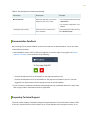
Documentation Feedback
We encourage you to provide feedback so that we can improve our documentation. You can use either
of the following methods:
•
Online feedback system—Click TechLibrary Feedback, on the lower right of any page on the Juniper
Networks TechLibrary site, and do one of the following:
•
Click the thumbs-up icon if the information on the page was helpful to you.
•
Click the thumbs-down icon if the information on the page was not helpful to you or if you have
suggestions for improvement, and use the pop-up form to provide feedback.
•
URL or page number, and software version (if applicable).
Requesting Technical Support
Technical product support is available through the Juniper Networks Technical Assistance Center (JTAC).
If you are a customer with an active Juniper Care or Partner Support Services support contract, or are
xvi

covered under warranty, and need post-sales technical support, you can access our tools and resources
online or open a case with JTAC.
•
JTAC policies—For a complete understanding of our JTAC procedures and policies, review the JTAC User
Guide located at https://www.juniper.net/us/en/local/pdf/resource-guides/7100059-en.pdf.
•
Product warranties—For product warranty information, visit https://www.juniper.net/support/warranty/.
•
JTAC hours of operation—The JTAC centers have resources available 24 hours a day, 7 days a week,
365 days a year.
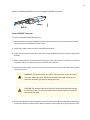
Self-Help Online Tools and Resources
For quick and easy problem resolution, Juniper Networks has designed an online self-service portal called
the Customer Support Center (CSC) that provides you with the following features:
•
Find CSC offerings: https://www.juniper.net/customers/support/
•
Search for known bugs: https://prsearch.juniper.net/
•
Find product documentation: https://www.juniper.net/documentation/
•
Find solutions and answer questions using our Knowledge Base: https://kb.juniper.net/
•
Download the latest versions of software and review release notes:
https://www.juniper.net/customers/csc/software/
•
Search technical bulletins for relevant hardware and software notifications:
https://kb.juniper.net/InfoCenter/
•
Join and participate in the Juniper Networks Community Forum:
https://www.juniper.net/company/communities/
•
Create a service request online: https://myjuniper.juniper.net
To verify service entitlement by product serial number, use our Serial Number Entitlement (SNE) Tool:
https://entitlementsearch.juniper.net/entitlementsearch/
Creating a Service Request with JTAC
You can create a service request with JTAC on the Web or by telephone.
•
Visit https://myjuniper.juniper.net.
•
Call 1-888-314-JTAC (1-888-314-5822 toll-free in the USA, Canada, and Mexico).
For international or direct-dial options in countries without toll-free numbers, see
https://support.juniper.net/support/requesting-support/.
xvii


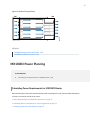
MX10003 System Overview
IN THIS SECTION
Benefits of the MX10003 Router | 19
MX10003 Router Hardware Overview | 20
MX10003 Hardware Components and CLI Terminology | 21
MX10003 Component Redundancy | 23
MX10003 Field-Replaceable Units | 24
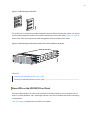
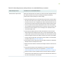
The Juniper Networks MX10003 Universal Routing Platform is an Ethernet-optimized edge router with
2.4Tb capacity that provide both switching and carrier-class Ethernet routing. The MX10003 router runs
Junos operating system (Junos OS), enabling a wide range of business and residential applications and
services, including high-speed transport and virtual private network (VPN) services, next-generation
broadband multiplay services, and high-volume Internet data center internetworking. Each router provides
full duplex, high-density Ethernet interfaces and high- capacity switching throughput and uses the Junos
Trio chipset for increased scalability of Layer 2/Layer 3 packet forwarding, buffering, and queuing.
Benefits of the MX10003 Router
•
Space-optimized, power-efficient cloud-era routing platform—The MX10003 caters to the edge and
Metro Ethernet needs of service providers, mobile operators, multiple-service operators in space- and
power-constrained environments. Delivering 2.4 Tbps of throughput in just three rack units (3 U), the
MX10003 delivers industry-leading port density and performance while consuming just 0.9 watts per
gigabit of throughput.
•
Integrated high-precision timing—The MX10003 router eliminates the need for external clocks by
supporting highly scalable and reliable hardware-based timing including Synchronous Ethernet for
frequency, and Precision Time Protocol (PTP) for frequency and phase synchronization. The router uses
a hybrid mode, combining Synchronous Ethernet and PTP, to achieve a high level of frequency (10 ppb)
and phase (<1.5 uS) accuracy.
•
Simplified management through Junos Fusion—You can use the MX10003 as aggregation devices in a
Junos Fusion Provider Edge deployment, where EX Series and QFX Series switches function as satellite
devices.
19

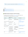
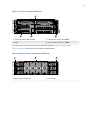
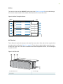
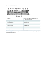
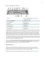
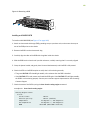
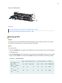
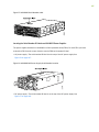
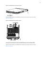
MX10003 Router Hardware Overview
The MX10003 router contains modular Routing Engines and multiple Packet Forwarding Engines. The
Packet Forwarding Engine has two “pseudo” Flexible PIC Concentrators (FPC 0 and FPC1). The single
Packet Forwarding Engine takes care of both ingress and egress packet forwarding.
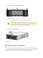
The MX10003 is a compact router, three rack units (3U) tall. Several routers can be stacked in a single
floor-to-ceiling rack for increased port density per unit of floor space.
The router provides two dedicated line card slots for Modular Port Concentrators (MPCs). MPCs install
into the line-card slots. The router supports two redundant Routing and Control Board (RCB). The RCB
houses the Routing Engine and Control Board. The router is powered by six dedicated AC/DC power
supply modules. Cooling is handled by four fan modules.
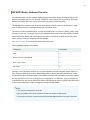
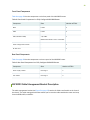
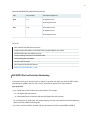
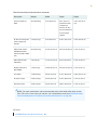
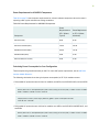
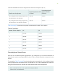
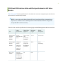
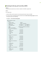
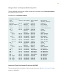
See Table 3 on page 20 for components supported on the router.
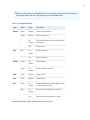
Table 3: MX10003 Router Components
DescriptionComponent
2MPC
2Routing and Control Board (RCB)
6Power supply module
4Fan module
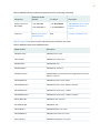
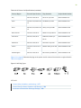
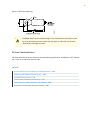
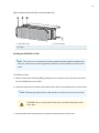
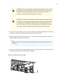
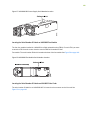
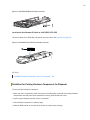
Starting in Junos OS Release 18.3R1, you can use the Mellanox 10-Gbps pluggable adapter (QSFP+ to
SFP+ adapter or QSA; model number: MAM1Q00A-QSA) to convert four lane-based ports to a single
lane-based SFP+ port. The QSA adapter has the QSFP+ form factor with a receptacle for the SFP+ module.
Use the QSA adapter to convert a 40-Gbps port to a 10-Gbps or a 1-Gbps port. You can configure the
4x10 Gbps ports on the fixed pic (6XQSFPP) and the QSFP28 ports on the non-MACSEC MIC (JNP-MIC1)
in the 1-Gbps mode, when the SFP is plugged in through the QSA adapter.
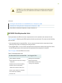
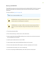
NOTE:
•
The interface name prefix must be xe.
•
Rate selectability at PIC level and port level does not support 1-Gbps speed.
•
For the link to come up, you must configure the no-auto-neg statement on the egress interface.
20
La pagina si sta caricando...
La pagina si sta caricando...
La pagina si sta caricando...
La pagina si sta caricando...
La pagina si sta caricando...
La pagina si sta caricando...
La pagina si sta caricando...
La pagina si sta caricando...
La pagina si sta caricando...
La pagina si sta caricando...
La pagina si sta caricando...
La pagina si sta caricando...
La pagina si sta caricando...
La pagina si sta caricando...
La pagina si sta caricando...
La pagina si sta caricando...
La pagina si sta caricando...
La pagina si sta caricando...
La pagina si sta caricando...
La pagina si sta caricando...
La pagina si sta caricando...
La pagina si sta caricando...
La pagina si sta caricando...
La pagina si sta caricando...
La pagina si sta caricando...
La pagina si sta caricando...
La pagina si sta caricando...
La pagina si sta caricando...
La pagina si sta caricando...
La pagina si sta caricando...
La pagina si sta caricando...
La pagina si sta caricando...
La pagina si sta caricando...
La pagina si sta caricando...
La pagina si sta caricando...
La pagina si sta caricando...
La pagina si sta caricando...
La pagina si sta caricando...
La pagina si sta caricando...
La pagina si sta caricando...
La pagina si sta caricando...
La pagina si sta caricando...
La pagina si sta caricando...
La pagina si sta caricando...
La pagina si sta caricando...
La pagina si sta caricando...
La pagina si sta caricando...
La pagina si sta caricando...
La pagina si sta caricando...
La pagina si sta caricando...
La pagina si sta caricando...
La pagina si sta caricando...
La pagina si sta caricando...
La pagina si sta caricando...
La pagina si sta caricando...
La pagina si sta caricando...
La pagina si sta caricando...
La pagina si sta caricando...
La pagina si sta caricando...
La pagina si sta caricando...
La pagina si sta caricando...
La pagina si sta caricando...
La pagina si sta caricando...
La pagina si sta caricando...
La pagina si sta caricando...
La pagina si sta caricando...
La pagina si sta caricando...
La pagina si sta caricando...
La pagina si sta caricando...
La pagina si sta caricando...
La pagina si sta caricando...
La pagina si sta caricando...
La pagina si sta caricando...
La pagina si sta caricando...
La pagina si sta caricando...
La pagina si sta caricando...
La pagina si sta caricando...
La pagina si sta caricando...
La pagina si sta caricando...
La pagina si sta caricando...
La pagina si sta caricando...
La pagina si sta caricando...
La pagina si sta caricando...
La pagina si sta caricando...
La pagina si sta caricando...
La pagina si sta caricando...
La pagina si sta caricando...
La pagina si sta caricando...
La pagina si sta caricando...
La pagina si sta caricando...
La pagina si sta caricando...
La pagina si sta caricando...
La pagina si sta caricando...
La pagina si sta caricando...
La pagina si sta caricando...
La pagina si sta caricando...
La pagina si sta caricando...
La pagina si sta caricando...
La pagina si sta caricando...
La pagina si sta caricando...
La pagina si sta caricando...
La pagina si sta caricando...
La pagina si sta caricando...
La pagina si sta caricando...
La pagina si sta caricando...
La pagina si sta caricando...
La pagina si sta caricando...
La pagina si sta caricando...
La pagina si sta caricando...
La pagina si sta caricando...
La pagina si sta caricando...
La pagina si sta caricando...
La pagina si sta caricando...
La pagina si sta caricando...
La pagina si sta caricando...
La pagina si sta caricando...
La pagina si sta caricando...
La pagina si sta caricando...
La pagina si sta caricando...
La pagina si sta caricando...
La pagina si sta caricando...
La pagina si sta caricando...
La pagina si sta caricando...
La pagina si sta caricando...
La pagina si sta caricando...
La pagina si sta caricando...
La pagina si sta caricando...
La pagina si sta caricando...
La pagina si sta caricando...
La pagina si sta caricando...
La pagina si sta caricando...
La pagina si sta caricando...
La pagina si sta caricando...
La pagina si sta caricando...
La pagina si sta caricando...
La pagina si sta caricando...
La pagina si sta caricando...
La pagina si sta caricando...
La pagina si sta caricando...
La pagina si sta caricando...
La pagina si sta caricando...
La pagina si sta caricando...
La pagina si sta caricando...
La pagina si sta caricando...
La pagina si sta caricando...
La pagina si sta caricando...
La pagina si sta caricando...
La pagina si sta caricando...
La pagina si sta caricando...
La pagina si sta caricando...
La pagina si sta caricando...
La pagina si sta caricando...
La pagina si sta caricando...
La pagina si sta caricando...
La pagina si sta caricando...
La pagina si sta caricando...
La pagina si sta caricando...
La pagina si sta caricando...
La pagina si sta caricando...
La pagina si sta caricando...
La pagina si sta caricando...
La pagina si sta caricando...
La pagina si sta caricando...
La pagina si sta caricando...
La pagina si sta caricando...
La pagina si sta caricando...
La pagina si sta caricando...
La pagina si sta caricando...
La pagina si sta caricando...
La pagina si sta caricando...
La pagina si sta caricando...
La pagina si sta caricando...
La pagina si sta caricando...
La pagina si sta caricando...
La pagina si sta caricando...
La pagina si sta caricando...
La pagina si sta caricando...
La pagina si sta caricando...
La pagina si sta caricando...
La pagina si sta caricando...
La pagina si sta caricando...
La pagina si sta caricando...
La pagina si sta caricando...
La pagina si sta caricando...
La pagina si sta caricando...
La pagina si sta caricando...
La pagina si sta caricando...
La pagina si sta caricando...
La pagina si sta caricando...
La pagina si sta caricando...
La pagina si sta caricando...
La pagina si sta caricando...
La pagina si sta caricando...
La pagina si sta caricando...
La pagina si sta caricando...
La pagina si sta caricando...
La pagina si sta caricando...
La pagina si sta caricando...
La pagina si sta caricando...
La pagina si sta caricando...
La pagina si sta caricando...
La pagina si sta caricando...
La pagina si sta caricando...
La pagina si sta caricando...
La pagina si sta caricando...
La pagina si sta caricando...
La pagina si sta caricando...
La pagina si sta caricando...
La pagina si sta caricando...
La pagina si sta caricando...
-
 1
1
-
 2
2
-
 3
3
-
 4
4
-
 5
5
-
 6
6
-
 7
7
-
 8
8
-
 9
9
-
 10
10
-
 11
11
-
 12
12
-
 13
13
-
 14
14
-
 15
15
-
 16
16
-
 17
17
-
 18
18
-
 19
19
-
 20
20
-
 21
21
-
 22
22
-
 23
23
-
 24
24
-
 25
25
-
 26
26
-
 27
27
-
 28
28
-
 29
29
-
 30
30
-
 31
31
-
 32
32
-
 33
33
-
 34
34
-
 35
35
-
 36
36
-
 37
37
-
 38
38
-
 39
39
-
 40
40
-
 41
41
-
 42
42
-
 43
43
-
 44
44
-
 45
45
-
 46
46
-
 47
47
-
 48
48
-
 49
49
-
 50
50
-
 51
51
-
 52
52
-
 53
53
-
 54
54
-
 55
55
-
 56
56
-
 57
57
-
 58
58
-
 59
59
-
 60
60
-
 61
61
-
 62
62
-
 63
63
-
 64
64
-
 65
65
-
 66
66
-
 67
67
-
 68
68
-
 69
69
-
 70
70
-
 71
71
-
 72
72
-
 73
73
-
 74
74
-
 75
75
-
 76
76
-
 77
77
-
 78
78
-
 79
79
-
 80
80
-
 81
81
-
 82
82
-
 83
83
-
 84
84
-
 85
85
-
 86
86
-
 87
87
-
 88
88
-
 89
89
-
 90
90
-
 91
91
-
 92
92
-
 93
93
-
 94
94
-
 95
95
-
 96
96
-
 97
97
-
 98
98
-
 99
99
-
 100
100
-
 101
101
-
 102
102
-
 103
103
-
 104
104
-
 105
105
-
 106
106
-
 107
107
-
 108
108
-
 109
109
-
 110
110
-
 111
111
-
 112
112
-
 113
113
-
 114
114
-
 115
115
-
 116
116
-
 117
117
-
 118
118
-
 119
119
-
 120
120
-
 121
121
-
 122
122
-
 123
123
-
 124
124
-
 125
125
-
 126
126
-
 127
127
-
 128
128
-
 129
129
-
 130
130
-
 131
131
-
 132
132
-
 133
133
-
 134
134
-
 135
135
-
 136
136
-
 137
137
-
 138
138
-
 139
139
-
 140
140
-
 141
141
-
 142
142
-
 143
143
-
 144
144
-
 145
145
-
 146
146
-
 147
147
-
 148
148
-
 149
149
-
 150
150
-
 151
151
-
 152
152
-
 153
153
-
 154
154
-
 155
155
-
 156
156
-
 157
157
-
 158
158
-
 159
159
-
 160
160
-
 161
161
-
 162
162
-
 163
163
-
 164
164
-
 165
165
-
 166
166
-
 167
167
-
 168
168
-
 169
169
-
 170
170
-
 171
171
-
 172
172
-
 173
173
-
 174
174
-
 175
175
-
 176
176
-
 177
177
-
 178
178
-
 179
179
-
 180
180
-
 181
181
-
 182
182
-
 183
183
-
 184
184
-
 185
185
-
 186
186
-
 187
187
-
 188
188
-
 189
189
-
 190
190
-
 191
191
-
 192
192
-
 193
193
-
 194
194
-
 195
195
-
 196
196
-
 197
197
-
 198
198
-
 199
199
-
 200
200
-
 201
201
-
 202
202
-
 203
203
-
 204
204
-
 205
205
-
 206
206
-
 207
207
-
 208
208
-
 209
209
-
 210
210
-
 211
211
-
 212
212
-
 213
213
-
 214
214
-
 215
215
-
 216
216
-
 217
217
-
 218
218
-
 219
219
-
 220
220
-
 221
221
-
 222
222
-
 223
223
-
 224
224
-
 225
225
-
 226
226
-
 227
227
-
 228
228
-
 229
229
-
 230
230


in altre lingue
- English: Juniper MX10003 User manual
Documenti correlati
-
Juniper MX10003 Hardware Guide
-
Juniper MX104 Hardware Guide
-
-
Juniper MX204 Manuale utente
-
-
Juniper PTX1000 Manuale utente
-
-
-
Juniper QFX5120-48Y-AFI2 Manuale utente
-
Juniper SRX320 Manuale utente
Altri documenti
-
IFM DF2208 Istruzioni per l'uso
-
Alpina E-Strap Manuale utente
-
 ZyXEL Communications ZoneDAS Manuale utente
-
Eaton JDB Installation Instructions Manual
-
Dell PowerStore Rack Guida Rapida
-
 Lutron Electronics LCP128 Guida d'installazione
-
Etymotic The BEAN Quiet Sound Amplifier Manuale utente
-
Allied Telesis AR400 series Installation And Safety Manual
-
Mellanox Technologies SX1410 Manuale utente
-

