ProLights DIGIDRIVERIP Manuale utente
- Categoria
- Proiettori
- Tipo
- Manuale utente
Questo manuale è adatto anche per

MANUALE UTENTE
USER MANUAL
IT - EN
DIGIDRIVERIP
DIGISTRIPIP50
DIGISTRIPIP100

REV.001-09/17
Music & Lights S.r.l. si riserva ogni diritto di elaborazione in qualsiasi forma delle presenti istruzioni per l’uso.
La riproduzione - anche parziale - per propri scopi commerciali è vietata.
Al ne di migliorare la qualità dei prodotti, la Music&Lights S.r.l. si riserva la facoltà di modicare, in
qualunque momento e senza preavviso, le speciche menzionate nel presente manuale di istruzioni.
Tutte le revisioni e gli aggiornamenti sono disponibili nella sezione 'Manuali' sul sito www.musiclights.it

3
DIGIDRIVERIP - DIGISTRIPIP50 - DIGISTRIPIP100
• DIGIDRIVERIP
• DIGISTRIPIP100 DIGISTRIPIP50
• Manuale utente
Contenuto dell'imballo:
INDICE
Sicurezza
Avvertenze generali
Attenzioni e precauzioni per l’installazione
1 Descrizione e specifiche tecniche
1. 1 DIGIDRIVERIP
1. 2 DIGISTRIPIP100
1. 3 DIGISTRIPIP50
1. 4 Elementi di comando e collegamenti
2 Installazione
2. 1 Montaggio
2. 2 Distanza massima di cablaggio
3 Funzioni e impostazioni
3. 1 Impostazione base
3. 2 Struttura menu
4 Schema di collegamento
5 Manutenzione
5. 1 Manutenzione e pulizia del sistema
5. 2 Sostituzione fusibile
4
4
5
6
7
8
9
9
10
11
12
13
13

DIGIDRIVERIP - DIGISTRIPIP50 - DIGISTRIPIP100
4
ATTENZIONE! Prima di effettuare qualsiasi operazione con l’unità, leggere con attenzione
questo manuale e conservarlo accuratamente per riferimenti futuri. Contiene informazioni
importanti riguardo l’installazione, l’uso e la manutenzione dell’unità.
SICUREZZA
Avvertenze generali
• I prodotti a cui questo manuale si riferisce sono conformi alle Direttive della Comunità Europea e per-
tanto recano la sigla .
• Il dispositivo funziona con pericolosa tensione di rete 230V~. Non intervenire mai al suo interno al di
fuori delle operazioni descritte nel presente manuale; esiste il pericolo di una scarica elettrica.
• È obbligatorio eettuare il collegamento ad un impianto di alimentazione dotato di un’eciente messa
a terra (apparecchio di Classe I secondo norma EN 60598-1). Si raccomanda, inoltre, di proteggere le
linee di alimentazione delle unità dai contatti indiretti e/o cortocircuiti verso massa tramite l’uso di
interruttori dierenziali opportunamente dimensionati.
• Le operazioni di collegamento alla rete di distribuzione dell’energia elettrica devono essere eettuate
da un installatore elettrico qualicato. Vericare che frequenza e tensione della rete corrispondono alla
frequenza ed alla tensione per cui l’unità è predisposta, indicate sulla targhetta dei dati elettrici.
• L’unità non per uso domestico, solo per uso professionale.
• Evitare di utilizzare l’unità:
- in luoghi soggetti a vibrazioni, o a possibili urti;
- in luoghi soggetti ad eccessiva umidità;
- in luoghi a temperatura superiore ai 45°C oppure ai -40°C.
• Evitare che nell’unità penetrino liquidi inammabili, acqua o oggetti metallici.
• Non smontare e non apportare modiche all’unità.
• Tutti gli interventi devono essere sempre e solo eettuati da personale tecnico qualicato. Rivolgersi al
più vicino centro di assistenza tecnica autorizzato.
• Se si desidera eliminare il dispositivo denitivamente, consegnarlo
per lo smaltimento ad un’istituzione locale per il riciclaggio.
Attenzioni e precauzioni per l’installazione
• Se il dispositivo dovesse trovarsi ad operare in condizioni dierenti da quelle descritte nel presente
manuale, potrebbero vericarsi dei danni; in tal caso la garanzia verrebbe a decadere. Inoltre, ogni altra
operazione potrebbe provocare cortocircuiti, incendi, scosse elettriche, rotture etc.
• Ogni persona coinvolta con l’installazione e la manutenzione di questo prodotto deve essere qualica-
ta e seguire le istruzioni di questo manuale.
• Prima di iniziare qualsiasi operazione di manutenzione o pulizia sull’unità togliere la tensione dalla rete
di alimentazione.
• Nell’eseguire qualsiasi intervento attenersi scrupolosamente a tutte le normative (in materia di sicurez-
za) vigenti nel paese di utilizzo.
• Installare l’unità in un luogo ben ventilato.
• Mantenere i materiali inammabili ad una distanza di sicurezza dall’unità.
• Non guardare direttamente il fascio luminoso. Tenete presente che i veloci cambi di luce possono pro-
vocare attacchi d’epilessia presso persone fotosensibili o epilettiche.
• Per la pulizia del prodotto non usare solventi tipo acetone o alcool per non danneggiare la nitura
esterna.

5
DIGIDRIVERIP - DIGISTRIPIP50 - DIGISTRIPIP100
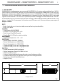
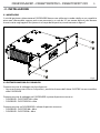
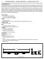
Fig.1
Disegno tecnico
84
483 263
- 1 - DESCRIZIONE E SPECIFICHE TECNICHE
1.1 DIGIDRIVERIP
DIGIDRIVERIP è un’alimentatore e processore del DIGISTRIPIP. Ha 2 uscite e può controllare no a 20 DIGI-
STRIPIP100 o 40 DIGISTRIPIP50, ognuno con la possibilità di controllare no a 3600 pixels in una unità rack,
disponendo di 20 universi DMX e 546 W di alimentazione. DIGIDRIVERIP non può controllare DIGISTRIP,
DIGITUBE e DIGITILE. DIGIDRIVERIP è compatibile con i protocolli Art-Net, Kling-Net e sACN e trasmette
segnale e alimentazione su un cavo XLR a 4 poli che permette il cablaggio in catena delle unità. L’interfac-
cia utente consiste in uno scermo OLED nero per i settaggi, selezione dei protocolli, indirizzi di rete e i test
pattern. Il grado IP è 65 e permette l’utilizzo per eventi all’esterno così l’utente non deve preoccuparsi di
pioggia e umidità.
BODY
• Body: Sturdy die-cast aluminium body conceived for long-time durability
• Body Color: Black
CONTROL
• Control units:20 DIGISTRIPIP
• Protocols: Art-Net, Kling-Net, sACN
• Pixel Control: Pixel2Pixel control
• Display: Black OLED high resolution display
ELECTRONICS
• Operating Temperature: -20° ~ +45°
ELECTRICAL
• Power Supply: 100-240V – 50/60Hz
• Power Consumption (at 230V):546 W
• Power Consumption (at 120V):570 W
• Output (at 230V):5 units on a single power line
• Output (at 120V):2 units on a single power line
PHYSICAL
• Signal Connection:2xRJ45 and 4p out
• Power Connection: PowerCON TRUE1 in/out
• IP:65 for outdoor events
• Cooling: Natural cooling of the peculiar chassis and to absence of fans
• Suspension And Fixing: Any position with “quick-lock” omega brackets
• Dimensions (WxHxD):483x263x84 mm
• Weight:4,47 kg

DIGIDRIVERIP - DIGISTRIPIP50 - DIGISTRIPIP100
6
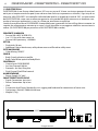
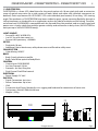
1000
88
100
128
34
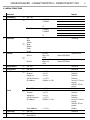
Fig.2Disegno tecnico
1.2 DIGISTRIPIP100
DIGISTRIPIP100 è una xture video lineare a LED con un passo di 10 mm e un’estesa gamma di accessori
ottici per un’ampia varietà di aspetti (nero e bianco latte incluso, trasparente su richiesta). Ogni strip di un
metro ha 100 LED RGB/FC con controllo individuale dei pixel e un angolo di visuale di 120°. Le meccaniche
del DIGISTRIPIP100 sono state studiate per garantire una grande essibilità attraverso un hardware scor-
revole sul retro per applicazioni su truss e sul lato per attaccarne uno all’altro.
L’unità di controllo esterna DIGIDRIVERIP è compatibile con i protocolli Art-Net e Kling-Net e trasmette sia
segnale che alimentazione attraverso un cavo a 4 poli che ore una maggiore stabilità e connessione in
catena (10 DIGISTRIPIP100 per porta no a 20 DIGISTRIPIP100 in totale).
SORGENTE LUMINOSA
• Source:100 x 0,25 W RGB LEDs
• Lux:1174 lux with clear cover lux
• Source Life Expectancy: >50.000 h
OTTICA
• Pixel pitch:10 mm
• Additional Optics:black cover, milky dome cover and at white milky cover
SISTEAM COLORE
• Color Mixing: RGB/FC
CORPO
• Body: Sturdy aluminum prole
• Body Color:White optic and body Black
CONTROLLO
• Control units:DIGIDRIVERIP
• Art-Net Channels:300 ch
• Protocols: Art-Net, Kling-Net
• Pixel Control: Pixel2Pixel control
ALIMENTAZIONE
• Power Supply: DC 48 V
CARATTESRISTICHE FISICHE
• Signal Connection: 4p in/out
• Power Connection: 4p in/out
• IP:65
• Suspension And Fixing: Bracket for truss rigging and hardware for connection of more units
• Dimensions (WxHxD):1000x34x100 mm
• Weight:2,7 kg

7
DIGIDRIVERIP - DIGISTRIPIP50 - DIGISTRIPIP100
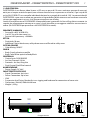
500
33
114
100
121
Fig.3Disegno tecnico
1.3 DIGISTRIPIP50
DIGISTRIPIP50 è una xture video lineare a LED con un passo di 10 mm e un’estesa gamma di accessori
ottici per un’ampia varietà di aspetti (nero e bianco latte incluso, trasparente su richiesta). Ogni strip di 50
cm ha 50 LED RGB/FC con controllo individuale dei pixel e un angolo di visuale di 120°. Le meccaniche del
DIGISTRIPIP50 sono state studiate per garantire una grande essibilità attraverso un hardware scorrevole
sul retro per applicazioni su truss e sul lato per attaccarne uno all’altro.
L’unità di controllo esterna DIGIDRIVERIP è compatibile con i protocolli Art-Net e Kling-Net e trasmette sia
segnale che alimentazione attraverso un cavo a 4 poli che ore una maggiore stabilità e connessione in
catena (20 DIGISTRIP50 per porta no a 40 DIGISTRIPIP50 in totale).
SORGENTE LUMINOSA
• Source:50 x 0,25 W RGB LEDs
• Lux:587 lux with clear cover lux
• Source Life Expectancy: >50.000 h
OTTICA
• Pixel pitch:10 mm
• Additional Optics:black cover, milky dome cover and at white milky cover
SISTEMA COLORE
• Color Mixing: RGB/FC
CORPO
• Body: Sturdy aluminum prole
• Body Color:White optic and body Black
CONTROLLO
• Control units:DIGIDRIVERIP
• Art-Net Channels:150 ch
• Protocols: Art-Net, Kling-Net
• Pixel Control: Pixel2Pixel control
ALIMENTAZIONE
• Power Supply: DC 48 V
CARATTERISTICHE FISICHE
• Signal Connection: 4p in/out
• Power Connection: 4p in/out
• IP:65
• Suspension And Fixing: Bracket for truss rigging and hardware for connection of more units
• Dimensions (WxHxD):500x34x100 mm
• Weight:1,35 kg

DIGIDRIVERIP - DIGISTRIPIP50 - DIGISTRIPIP100
8
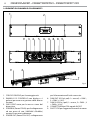
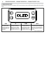
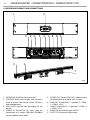
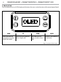
1. FORI DI FISSAGGIO per il montaggio rack.
2. PANNELLO DI CONTROLLO con display e 4
pulsanti per accesso e gestione delle diverse
funzioni.
3. GND POINT usato per la messa a terra del
dispositivo.
4. POWER IN ( PowerCON IN): per il collegamento
ad una presa di rete (100-240V~/50-60Hz)
tramite il cavo rete in dotazione.
5. POWER OUT (PowerCON OUT): collegamento
per l'alimentazione all'unità successiva.
6. DMX OUT (XLR a 4 poli): 1= massa,2 = DMX -,
3 = DMX +, 4 N/C.
7. DMX IN (XLR a 4 poli):1 = massa, 2 = DMX -, 3
= DMX +, 4 N/C.
8. CONNETTORI EtherCON segnale IN/OUT.
9. SAFETY EYE per l’aggancio al cavo di sicurezza.
1
2
3
4
5
6
6
8
6
7
8
9
9
9
Fig.4
1.4 ELEMENTI DI COMANDO E COLLEGAMENTI

9
DIGIDRIVERIP - DIGISTRIPIP50 - DIGISTRIPIP100
- 2 - INSTALLAZIONE
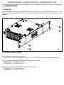
2.1 MONTAGGIO
L‘ unità di gestione e alimentazione DIGIDRIVERIP deve essere collocata in modo stabile su una supercie
piana non inammabile, oppure può essere montata in un rack da 19” per mezzo delle viti che devono
essere inserite negli appositi fori presenti sul corpo del dispositivo, come mostrato in gura 7.
Fig.5
2.2 DISTANZA MASSIMA DI CABLAGGIO
Distanza massima di cablaggio tra due dispositivi:
• Nessuna distanza massima tra 2 dispositivi, purchè la distanza dell’ultima DIGISTRIP sia massimo 60m
dalla DIGIDRIVER
Distanza massima di cablaggio tra DIGIDRIVERIP e primo dispositivo connesso:
• DIGIDRIVER - DIGISTRIPIP100 = 60m
• DIGIDRIVER - DIGISTRIPIP50 = 60m
Distanza massima tra DIGIDRIVERIP e ultimo dispositivo connesso:
• DIGIDRIVER - DIGISTRIP100 = 60 m
• DIGIDRIVER - DIGISTRIP50 = 60 m

DIGIDRIVERIP - DIGISTRIPIP50 - DIGISTRIPIP100
10
MENU UP DOWN ENTER
Per scorrere il menu
principale o tornare ad
una opzione del menu
precedente
Per scorrere attraverso le
diverse funzioni in ordine
discendente o aumentare il
valore della funzione stessa
Per scorrere attraverso le
diverse funzioni in ordine
ascendente o diminuire il
valore della funzione stessa
Per entrare nel menu selezionato o
confermare il valore attuale della
funzione o l'opzione all'interno di
un menu
3.2 IMPOSTAZIONE BASE
Il DIGIDRIVERIP dispone di un display OLED e 4 pulsanti per accesso alle funzioni del pannello di controllo
(g.9).
Fig.6 - Funzione dei tasti

11
DIGIDRIVERIP - DIGISTRIPIP50 - DIGISTRIPIP100
3.3 STRUTTURA MENU
Main Level Remark
1 Auto Address
ð
No - Yes
2 Viem Linked Fixtures
ð
Port A 1.P100X IP
2.P100X IP
……
18.
Port B
1.P100X IP
2.P100X IP
……
18.
3 Led Output
ð
O
Red
Green
Blue
White
Fade
Scroll
Default: O
4 Protocol
ð
Port A
Art - Net
Kling - Net
sACN
Device ID 101760422
Default: Art-Net
Port B
Art - Net
Kling - Net
sACN
Device ID 101760423
Default: Art-Net
5 Display Inverse
ð
No -Yes Default: No
6 Factory Reset
ð
No -Yes Default: O
7 Port A
ð
Net
Subnet
Universe
sACN Universe
IP Address
<0 - 127>
<0 - 15>
<0 - 15>
<1 - 247>
IP Address <1-10>
Default: 1
Default: 0
Default: 0
Default: 0
Art-net(IP 1-126.xxx.
xxx.xxx)
SACN(IP:1-255.xxx.
xxx.xxx)
Dmx Address <1 - 512> Default: 1
Port B
ð
Net
Subnet
Universe
sACN Universe
IP Address
<0 - 127>
<0 - 15>
<0 - 15>
<1 - 247>
IP Address <1-10>
Default : 1
Default: 0
Default: 0
Default: 0
Art-net(IP 1-126.xxx.
xxx.xxx)
SACN(IP:1-255.xxx.
xxx.xxx)
Dmx Address <1 - 512> Default: 1
8 Screen Lock
ð
No -Yes Default: No
9 Software Version
ð
Port A-V1.0
Port B-V1.0

DIGIDRIVERIP - DIGISTRIPIP50 - DIGISTRIPIP100
12
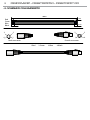
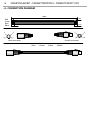
- 4 - SCHEMA DI COLLEGAMENTO
Red
3
4
1
2
Green
Blue
Black
1-Red 2-Green
3-Blue
4-Black
Male connector Female connector
2cm2cm
3mm
3mm
100cm
3
4
1
2

13
DIGIDRIVERIP - DIGISTRIPIP50 - DIGISTRIPIP100
5 - MANUTENZIONE
5.1 MANUTENZIONE E PULIZIA DEL SISTEMA
• Durante gli interventi, assicurarsi che l’area sotto il luogo di installazione sia libera da personale non
qualicato.
• Tutte le viti utilizzate per l’installazione dell’unità e le sue parti devono essere assicurate saldamente e
non devono essere corrose.
• Alloggiamenti, elementi di ssaggio e di installazione (sotto, truss, sospensioni) devono essere total-
mente esenti da qualsiasi deformazione.
• I cavi di alimentazione devono essere in condizione impeccabile e devono essere sostituiti immediata-
mente nel momento in cui anche un piccolo problema viene rilevato.
Per mantenere prestazioni ottimali e ridurre al minimo l’usura, è necessario pulire questo prodotto fre-
quentemente. Uso e l’ambiente sono fattori che contribuiscono a determinare la frequenza di pulizia.
Come regola generale, il dispositivo deve essere pulito almeno due volte al mese. L’accumulo di polvere
riduce la luminosità e può causare il surriscaldamento. L’utilizzo e l’ambiente sono fattori che contribuisco-
no a determinare la frequenza di pulizia.
Per la pulizia del prodotto, seguire le istruzioni riportate di seguito:
• Scollegare il dispositivo dall’alimentazione elettrica.
• Attendere nché l’unità non si sia rareddata.
• Utilizzare un compressore d’aria o una spazzola morbida per rimuovere la polvere accumulata sulla
supercie esterna.
• Per la pulizia usare un panno morbido, pulito e un detergente per vetri come si trovano in commercio.
• Delicatamente lucidare le superci no a che non siano prive di lanugine.
NOTA - Non aprire il prodotto per la pulizia o la manutenzione.
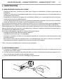
5.2 SOSTITUZIONE FUSIBILE
1. Assicurarsi di scollegare il cavo di alimentazione dell’unità prima di sostituire un fusibile bruciato con
uno dello stesso tipo e valore.
2. Con un cacciavite, rimuovere il portafusibile dalla sua sede e il fusibile bruciato dal suo supporto; sosti-
tuire il fusibile con uno identico per tipologia e valore.
3. Inserire il portafusibile al suo posto e ricollegare l’alimentazione.
Fig.7

All rights reserved by Music & Lights S.r.l. No part of this instruction manual may be
reproduced in any form or by any means for any commercial use.
In order to improve the quality of products, Music&Lights S.r.l. reserves the right to modify the
characteristics stated in this instruction manual at any time and without prior notice.
All revisions and updates are available in the ‘manuals’ section on site www.musiclights.it

1
DIGIDRIVERIP - DIGISTRIPIP50 - DIGISTRIPIP100
Packing content
• DIGIDRIVERIP
• DIGISTRIPIP100 DIGISTRIPIP50
• User manual
TABLE OF CONTENTS
Safety
General instructions
Warnings and installation precautions
1 Description and Technical specifications
1. 1 DIGIDRIVERIP
1. 2 DIGISTRIPIP100
1. 3 DIGISTRIPIP50
1. 3 Operating elements and connections
2 Installation
2. 1 Mounting
2. 2 Maximum cable distance
3 Functions and settings
3. 1 Operation
3. 2 Basic setup
3. 3 Menu structure
4 Connection diagram
5 Maintenance
5. 1 Maintenance and cleaning the unit
5. 2 Fuse replacement
2
2
3
4
5
6
7
7
8
8
9
10
11
11

DIGIDRIVERIP - DIGISTRIPIP50 - DIGISTRIPIP100
2
WARNING! Before carrying out any operations with the unit, carefully read this instruction
manual and keep it with cure for future reference. It contains important information about
the installation, usage and maintenance of the unit.
SAFETY
General instruction
• The products referred to in this manual conform to the European Community Directives and are there-
fore marked with .
• The unit is supplied with hazardous network voltage (230V~). Leave servicing to skilled personnel only.
Never make any modications on the unit not described in this instruction manual, otherwise you will
risk an electric shock.
• Connection of the power adapter must be made to a power supply system tted with ecient earthing
(Class I appliance according to standard EN 60598-1). It is, moreover, recommended to protect the
supply lines of the units from indirect contact and/or shorting to earth by using appropriately sized
residual current devices.
• The connection to the main network of electric distribution must be carried out by a qualied electrical
installer. Check that the voltage correspond to those for which the unit is designed as given on the
electrical data label.
• This unit is not for home use, only professional applications.
• Never use the xture under the following conditions:
- in places subject to vibrations or bumps;
- in places subject to excessive humidity;
- in places with a temperature of over 45 °C or -40°C.
• Make certain that no inammable liquids, water or metal objects enter the xture.
• Do not dismantle or modify the xture.
• All work must always be carried out by qualied technical personnel. Contact the nearest sales point for
an inspection or contact the manufacturer directly.
• If the unit is to be put out of operation denitively, take it to a local recycling
plant for a disposal which is not harmful to the environment.
Warnings and installation precautions
• If this device will be operated in any way dierent to the one described in this manual, it may suer
damage and the guarantee becomes void. Furthermore, any other operation may lead to dangers like
short circuit, burns, electric shock, etc.
• Every person involved with installation and maintenance of this device have to be qualied and follow
the instructions of this manual.
• Before starting any maintenance work or cleaning the projector, cut o power from the main supply.
• Always additionally secure the projector with the safety rope. When carrying out any work, always
comply
scrupulously with all the regulations (particularly regarding safety) currently in force in the country
in which the xture’s being used.
• Install the xture in a well ventilated place.
• Keep any inammable material at a safe distance from the xture.
• Never look directly at the light beam. Please note that fast changes in lighting, e. g. ashing light, may
trigger epileptic seizures in photosensitive persons or persons with epilepsy.
• When cleaning product, please do not use solvents such as acetone or alcohol, since they may damage
the of the unit outer nish and the printings on the panels.

3
DIGIDRIVERIP - DIGISTRIPIP50 - DIGISTRIPIP100
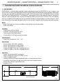
- 1 - DESCRIPTION AND TECHNICAL SPECIFICATIONS
1.1 DIGIDRIVERIP
DIGIDRIVERIP is a driver which provides power and processing to the DIGISTRIPIP. It has 2 outputs and
can control up to 20 DIGISTRIPIP100 and 40 DIGISTRIPIP50 each oering the control of up to 3600 pixels
in a one rack unit, oering 20 DMX universes and 546 W of power in out. DIGIDRIVERIP can not control
DIGISTRIP, DIGITUBE and DIGITILE. DIGIDRIVERIP is compatible with Art-Net, Kling-Net and sACN protocols
and runs signal and power over a 4 pole XLR cable that allow wiring of units in a chain. The user interface
consists in a black OLED display for settings, protocol selection, Network address and test patterns. The IP
rate is 65 to allow the usage in outdoor events so the user don’t need to take care about humidity and rain.
BODY
• Body: Sturdy die-cast aluminium body conceived for long-time durability
• Body Color: Black
CONTROL
• Control units:20 DIGISTRIPIP
• Protocols: Art-Net, Kling-Net, sACN
• Pixel Control: Pixel2Pixel control
• Display: Black OLED high resolution display
ELECTRONICS
• Operating Temperature: -20° ~ +45°
ELECTRICAL
• Power Supply: 100-240V – 50/60Hz
• Power Consumption (at 230V):546 W
• Power Consumption (at 120V):570 W
• Output (at 230V):5 units on a single power line
• Output (at 120V):2 units on a single power line
PHYSICAL
• Signal Connection:2xRJ45 and 4p out
• Power Connection: PowerCON TRUE1 in/out
• IP:65 for outdoor events
• Cooling: Natural cooling of the peculiar chassis and to absence of fans
• Suspension And Fixing: Any position with “quick-lock” omega brackets
• Dimensions (WxHxD):483x263x84 mm
• Weight:4,47 kg
Fig.1
Technical drawing
84
483 263

DIGIDRIVERIP - DIGISTRIPIP50 - DIGISTRIPIP100
4
1000
88
100
128
34
Fig.2Disegno tecnico
1.2 DIGISTRIPIP100
DIGISTRIPIP100 is a linear LED video xture for the rental market wih 10 mm pixel pitch and an extensive
range of optical accessories for a wide variety of looks (black and white milk included, transparent on de-
mand). Each strip features 100 LED RGB/FC LEDs with individual pixel control, 1 meter long, 120° viewing
angle. The mechanics of DIGISTRIPIP100 have been studied to grant a great mounting exibility through a
sliding hardwares on the back for truss application and on the side for multiple vertical linking. The exter-
nal control unit DIGIDRIVERIP is compatible with Art-Net and Kling-Net protocol, and runs both signal and
power over a 4 poles cable that provides greater stability and connection in daisy chain (10 DIGISTRIP for
each port up to 20 DIGISTRIPIP100 totaly).
LIGHT SOURCE
• Source:100 x 0,25 W RGB LEDs
• Lux:1174 lux with clear cover lux
• Source Life Expectancy: >50.000 h
OPTICS
• Pixel pitch:10 mm
• Additional Optics:black cover, milky dome cover and at white milky cover
COLOR SYSTEM
• Color Mixing: RGB/FC
BODY
• Body: Sturdy aluminum prole
• Body Color:White optic and body Black
CONTROL
• Control units:DIGIDRIVERIP
• Art-Net Channels:300 ch
• Protocols: Art-Net, Kling-Net
• Pixel Control: Pixel2Pixel control
ELECTRICAL
• Power Supply: DC 48 V
PHYSICAL
• Signal Connection: 4p in/out
• Power Connection: 4p in/out
• IP:65
• Suspension And Fixing: Bracket for truss rigging and hardware for connection of more units
• Dimensions (WxHxD):1000x34x100 mm
• Weight:2,7 kg

5
DIGIDRIVERIP - DIGISTRIPIP50 - DIGISTRIPIP100
500
33
114
100
121
Fig.3Disegno tecnico
1.3 DIGISTRIPIP50
DIGISTRIPIP50 is a linear LED video xture for the rental market wih 10 mm pixel pitch and an extensive
range of optical accessories for a wide variety of looks (black and white milk included, transparent on
demand). Each strip features 50 LED RGB/FC LEDs with individual pixel control, 50 cm long, 120° viewing
angle. The mechanics of DIGISTRIPIP50 have been studied to grant a great mounting exibility through a
sliding hardwares on the back for truss application and on the side for multiple vertical linking. The exter-
nal control unit DIGIDRIVERIP is compatible with Art-Net and Kling-Net protocol, and runs both signal and
power over a 4 poles cable that provides greater stability and connection in daisy chain (20 DIGISTRIP for
each port up to 40 DIGISTRIPIP50 totaly).
LIGHT SOURCE
• Source:50 x 0,25 W RGB LEDs
• Lux:587 lux with clear cover lux
• Source Life Expectancy: >50.000 h
OPTICS
• Pixel pitch:10 mm
• Additional Optics:black cover, milky dome cover and at white milky cover
COLOR SYSTEM
• Color Mixing: RGB/FC
BODY
• Body: Sturdy aluminum prole
• Body Color:White optic and body Black
CONTROL
• Control units:DIGIDRIVERIP
• Art-Net Channels:150 ch
• Protocols: Art-Net, Kling-Net
• Pixel Control: Pixel2Pixel control
ELECTRICAL
• Power Supply: DC 48 V
PHYSICAL
• Signal Connection: 4p in/out
• Power Connection: 4p in/out
• IP:65
• Suspension And Fixing: Bracket for truss rigging and hardware for connection of more units
• Dimensions (WxHxD):500x34x100 mm
• Weight:1,35 kg

DIGIDRIVERIP - DIGISTRIPIP50 - DIGISTRIPIP100
6
1.4 OPERATING ELEMENTS AND CONNECTIONS
1
2
3
4
5
6
6
8
6
7
8
9
9
9
1. MOUNTING HOLES for xing the rack.
2. CONTROL PANEL with display and 4 buttons
used to access the control panel functions
and manage them.
3. GND POINT used for the grounding of the
device.
4. POWER IN (PowerCON IN) mains plug for
connection to a socket (100-240V~/50/60Hz)
via the supplied mains cable.
5. POWER OUT (PowerCON OUT): power output
for connection of multiple units in series.
6. DMX OUT (4-pole XLR): 1 = ground, 2 = DMX-,
3 = DMX+, 4 N/C.
7. DMX IN (4-pole XLR): 1 = ground, 2 = DMX-, 3
= DMX+, 4 N/C.
8. EtherCON connector Signal IN/OUT .
9. SAFETY EYE to attach safety cable.
Fig.4
La pagina si sta caricando...
La pagina si sta caricando...
La pagina si sta caricando...
La pagina si sta caricando...
La pagina si sta caricando...
La pagina si sta caricando...
La pagina si sta caricando...
La pagina si sta caricando...
-
 1
1
-
 2
2
-
 3
3
-
 4
4
-
 5
5
-
 6
6
-
 7
7
-
 8
8
-
 9
9
-
 10
10
-
 11
11
-
 12
12
-
 13
13
-
 14
14
-
 15
15
-
 16
16
-
 17
17
-
 18
18
-
 19
19
-
 20
20
-
 21
21
-
 22
22
-
 23
23
-
 24
24
-
 25
25
-
 26
26
-
 27
27
-
 28
28


ProLights DIGIDRIVERIP Manuale utente
- Categoria
- Proiettori
- Tipo
- Manuale utente
- Questo manuale è adatto anche per
in altre lingue
- English: ProLights DIGIDRIVERIP User manual
Documenti correlati
-
ProLights DIGIDRIVERIP Scheda dati
-
-
-
-
-
-
-
-