DTS Synergy 5 Spot Manuale utente
- Categoria
- Proiettori
- Tipo
- Manuale utente


2
Le informazioni contenute in questo documento sono state attentamente redatte e
controllate. Tuttavia non è assunta alcuna responsabilità per eventuali inesattezze.
Tutti i diritti sono riservati e questo documento non può essere copiato, fotocopiato,
riprodotto per intero o in parte senza previo consenso scritto della D.T.S .
D.T.S. si riserva il diritto di apportare senza preavviso cambiamenti e modifiche
estetiche , funzionali o di design a ciascun proprio prodotto. D.T.S non assume alcuna
responsabilità sull’uso o sull’applicazione dei prodotti o dei circuiti descritti.
The information contained in this publication has been carefully prepared and
checked. However, no responsibility will be taken for any errors. All rights are
reserved and this document cannot be copied, photocopied or reproduced, in part or
completely, without prior written consent from D.T.S.
D.T.S. reserves the right to make any aesthetic, functional or design modifications to
any of its products without prior notice. D.T.S. assumes no responsibility for the use or
application of the products or circuits described herein.
Les informations contenues dans le présent manuel ont été rédigées et contrôlées
avec le plus grand soin. Nous déclinons toutefois toute responsabilité en cas
d'éventuelles inexactitudes. Tous droits réservés. Ce document ne peut être copié,
photocopié ou reproduit, dans sa totalité ou partiellement, sans le consentement
préalable de D.T.S.
D.T.S. se réserve le droit d'apporter toutes modifications et améliorations esthétiques,
fonctionnelles ou de design, sans préavis, à chacun de ses produits. D.T.S. décline
toute responsabilité sur l'utilisation ou sur l'application des produits ou des circuits
décrits.
Las informaciones contenidas en este documento han sido cuidadosamente
redactadas y controladas. Con todo, no se asume ninguna responsabilidad por
eventuales inexactitudes. Todos los derechos han sido reservados y este documento
no puede ser copiado, fotocopiado o reproducido, total o parcialmente, sin previa
autorización escrita de D.T.S.
D.T.S. se reserva el derecho a aportar sin previo aviso cambios y modificaciones de
carácter estético, funcional o de diseño a cada producto suyo. D.T.S. no se asume
responsabilidad de ningún tipo sobre la utilización o sobre la aplicación de los
productos o de los circuitos descritos.

3
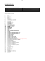
INDEX:
1 - SYMBOLS ................................................................................................................ 4
2 - GENERAL WARNING ............................................................................................. 5
3 - GENERAL WARRANTY CONDITIONS ................................................................... 5
4 - TECHNICAL FEATURES ........................................................................................ 6
5 - ACCESSORIES ....................................................................................................... 8
6 - IMPORTANT SAFETY INFORMATION ................................................................... 9
6.1 Fire prevention...................................................................................................... 9
6.2 Prevention of electric shock .................................................................................. 9
6.3 Safety ................................................................................................................... 9
6.4 Level of protection against the penetration of solid and liquid objects ................ 10
6.5 Waste Electrical and Electronic Equipment (WEEE) directive ............................ 10
6.6 Long-life auto-charging buffer battery ................................................................. 10
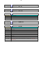
7 - PAN / TILT LOCK .................................................................................................. 11
8 - VOLTAGE AND FREQUENCY .............................................................................. 11
9 - INSTALLATION ..................................................................................................... 12
9.1 Safety cable ........................................................................................................ 13
9.2 Protection against liquids .................................................................................... 14
9.3 Movement ........................................................................................................... 14
9.4 Risk of fire .......................................................................................................... 14
9.5 Forced ventilation ............................................................................................... 14
9.6 Ambient temperature .......................................................................................... 14
10 - MAINS CONNECTION ......................................................................................... 15
10.1 Protection ......................................................................................................... 15
11 - DMX SIGNAL CONNECTION .............................................................................. 16
11.1 DMX addresses ................................................................................................ 17
11.2 Selecting the DMX address .............................................................................. 17
12 - ART-NET / SACN SIGNAL CONNECTION ......................................................... 18
12.1 Direct Ethernet operation .................................................................................. 18
12.2 Ethernet to DMX operation ............................................................................... 19
13 - RDM FUNCTIONS ............................................................................................... 20
14 - FIRMWARE UPDATING ...................................................................................... 20
15 - DISPLAY FUNCTIONS ........................................................................................ 22
16 - OPENING THE PROJECTOR HOUSING ............................................................ 32
17 - REMOVING / REPLACING THE ROTATING GOBOS ........................................ 34
18 - PERIODIC CLEANING ........................................................................................ 36
18.1 Lenses and reflectors ....................................................................................... 36
18.2 Fans and air passages ..................................................................................... 36
19 - PERIODIC CONTROLS ....................................................................................... 36
20 - DMX PROTOCOL ................................................................................................ 37
21 - ROTATING GOBO WHEEL ................................................................................. 62
22 - FIXED GOBO WHEEL ......................................................................................... 62
23 - COLOUR WHEEL ................................................................................................ 63

4
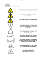
1- SYMBOLS
Graphic symbols used on this manual:
THIS SYMBOL INDICATES A HOT SURFACE
THIS SYMBOL INDICATES ELECTRIC
SHOCK RISK
THIS SYMBOL INDICATES GENERAL RISK
THIS SYMBOL MEANS “SUITABLE FOR
MOUNTING ON NORMALLY FLAMMABLE
SURFACES”
THIS SYMBOL MEANS “SUITABLE FOR
INDOOR USE ONLY”
THIS SYMBOL INDICATES THE MAXIMUM
OPERATING AMBIENT TEMPERATURE
THIS SYMBOL INDICATES THE MINIMUM
DISTANCE FROM THE OBJECTS AND THE
PEOPLE LIT BY THE LIGHT BEAM
THIS SYMBOL MEANS “DO NOT STARE
AT THE OPERATING LIGHT SOURCE”
THIS SYMBOL INDICATES
PHOTOBIOLOGICAL SAFETY
!

5
THIS SYMBOL INDICATES THE EUROPEAN
COMMUNITY DIRECTIVE 2012/19/EU ON
WASTE ELECTRICAL AND ELECTRONIC
EQUIPMENT (WEEE)
THIS SYMBOL MEANS “DISPOSE THE
INTERNAL BATTERY AT THE END OF ITS LIFE
ACCORDING TO THE REGULATION IN FORCE”
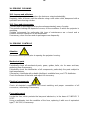
2- GENERAL WARNING
Read the instruction contained in this user manual carefully, as they give important
information regarding safety during installation, use and maintenance.
The unit is not for household use and must be installed by a qualified electrician or
experienced person.
The device must always be equipped with an efficient ground connection.
3- GENERAL WARRANTY CONDITIONS
The unit is guaranteed for 36 months from the date of purchase against manufacturing
material defects.
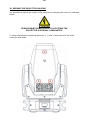
WARNING!
NEVER EXPOSE THE FRONT LENS
TO SUNLIGHT FROM ANY ANGLE
TO AVOID DAMAGE OF
HEAD INTERNAL PARTS.
Front lens could become powerful
magnifying glass if exposed towards the
sun or any strong artificial light source;
this can cause damage of head internal
parts, even for few seconds and even
when the unit is off.
The last command before switch off:
point the front lens down towards the
ground.

6
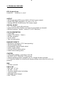
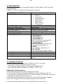
4- TECHNICAL FEATURES
DTS Product Code:
03.MS022 SYNERGY 5 SPOT
OUTPUT
• 420 W pure white LED source (7000 K 16.500 Lumens output)
• Double CRI (DMX-selectable): CRI >90 or CRI >75
• Average LED life: 50,000 hours (70% lumen output)
OPTICAL GROUP
• 5.5° - 43° linear zoom with autofocus
• Linear soft frost filter (Medium and Heavy frost available on demand)
• Electronic dimmer / shutter / strobe (0.3 to 33.3 flash/sec)
COLOR GENERATION
• Linear CMY
• Linear CTO (3000 K – 7000 K)
• Gel filter emulation
• 6-color wheel
• Two-color generation
DYNAMIC EFFECTS
• Dynamove FX Engine (DTS Patent pending)
• Virtual Animation Wheel
• Customizable rotating 6-gobo wheel
• Fixed 13-gobo wheel
• Circular 24-facet rotating prism
• Linear 6-facet rotating prism
CONTROL
• LCD graphic display + 4 soft keys; Auto-flip
• Art-Net 4, sACN, RDM/DMX 512 protocols
• Internal operating system updatable via DTS dongle firmware uploader
• Li-Fe backup battery for controlling the display settings even when the unit is not
powered
DMX
• 36 DMX channels
PAN & TILT
• Pan: 540°: 2.7 sec.
• Tilt: 240°: 1.6 sec.
• Tri-phase stepper motor technology
• 16-bit resolution
• Selectable speed ranges
• Pan / Tilt lock

7
POWER SUPPLY
• Full-range 100-240Vac 50-60 Hz
• Power consumption: 580W max
CONNECTIONS
• DMX: XLR 3-pole and 5-pole In / Out panel connectors
• Power supply: powerCON TRUE1 In / Out panel connectors
• Art-Net / sACN: etherCON RJ45 panel connector
INTERNAL SAFETY DEVICES
Overvoltage and overtemperature circuits protection
OPERATING TEMPERATURE
-10° / 40°C
PHYSICAL
• IP20
• Weight: 32 Kg (70.4 lbs)
Finishing: Black
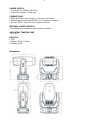
Dimensions

8
5- ACCESSORIES
As standard
1 x PowerCON TRUE1 female cable connector (Code 0520P066)
1 x XLR 5 pins female cable connector (Code 0508B147)
1 x XLR 5 pins female cable connector (Code 0508B148)
2 x Omega clamp with “Fast Lock” connection 1/4 turn (Code 02K00549)
1 x User’s manual
Optional (on request)
• Flightcase for 2 units (Code 0521C073)
• Synergy Protective Packaging Foam – 560x495x650mm – 2 pcs needed in each
flightcase (Code 0512K146.1)
• Soft Frost filter kit (Code 02SK0410)
• Medium Frost filter kit (Code 02SK0428)
• Heavy Frost filter kit (Code 02SK0430)
• Aliscaf clamp for tube diameter 48-51 mm (Max load 200 Kg) (code 0521A033)
(indicated for any kind of loads vertical / horizontal)
• Professional Quick trigger clamp (Max load 100 Kg) (code 0521A037) (not indicated
for horizontal load)
• DTS Dongle firmware uploader (code 03.LA.206)
6- IMPORTANT SAFETY INFORMATION
6.1 Fire prevention:
-It is permissible to place the unit on normally flammable surfaces.
Suitable for mounting on normally flammable materials surfaces greater than 200°C
with some combustion time lag.
-Minimum distance from the objects and the people lit by the light beam: 0,5 m.
-Replace any blown or damaged fuses only with those of identical value (T 8A 250V).
Refer to the wiring diagrams if there is any doubt.
-Connect the projector to mains power via a thermal magnetic circuit breaker.
6.2 Prevention of electric shock:
-High voltage is present inside the unit.
Unplug the unit prior to performing any function which involves touching the inside of
the moving head.
-The level of technology inherent in the SYNERGY 5 SPOT requires the assistance of
specialised personnel for all servicing. Please refer to an authorised DTS service
centre.
-A good earth connection is essential for proper functioning of the projector.
-Never connect the unit without proper earth connection.
-The fixture should be located in places with a good air ventilation.

9
6.3 Safety:
-Risk Group 2 product according to EN 62471.
CAUTION. Do not look directly into the light output and do not view the light beam with
optical instruments or any device that may concentrate the beam.
May be harmful to the eyes and skin.
-Do not stare at the operating light source.
-The light source contained in this luminaire shall only be replaced by the
manufacturer or his service agent or a similar qualified person.
-The unit is not for household use and must be installed by a qualified electrician or
experienced person.
-The projector should always be installed with bolts, clamps and other tools that are
capable of supporting the weight of the unit.
-Always use a safety cable to sustain the weight of the unit in case of the failure of the
main fixing point.
-The external surface of the unit, at various points, may exceed 50°C. Never handle
the unit until at least 5 minutes have elapsed since the unit was turned off.
-Never install the fixture in an enclosed area lacking sufficient air flow.
The ambient temperature should not exceed 40°C.
6.4 Level of protection against the penetration of solid and liquid objects:
-The projector is classified as an ordinary appliance and its protection level against the
penetration of solid and liquid objects is IP20.
Suitable for indoor use only.
6.5 Waste Electrical and Electronic Equipment (WEEE) directive:
- The projector, accessories and packaging should be sorted for environmental-friendly
recycling.
For EC countries: according to the European Directive 2012/19/EU for Waste
Electrical and Electronic Equipment and its implementation into national right,
luminaires that are no longer usable must be collected separately and disposed of in
an environmentally correct manner.
6.6 Long-life auto-charging buffer battery:
-The projector contains a rechargeable lead-acid or lithium iron tetraphosphate battery.
To preserve the environment, please dispose the battery at the end of its life according
to the regulation in force.
!
!

10
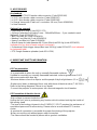
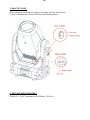
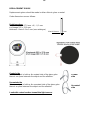
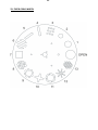
7- PAN / TILT LOCK
When moving or servicing the unit you can apply the Pan and Tilt lock.
To lock or release the Pan and Tilt refer to the picture below.
8- VOLTAGE AND FREQUENCY
SYNERGY 5 SPOT operates at 100-240Vac 50-60 Hz.

11
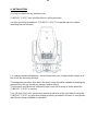
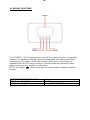
9- INSTALLATION
The unit is suitable for dry locations only.
SYNERGY 5 SPOT may be either floor or ceiling mounted.
For floor mounting installations, SYNERGY 5 SPOT is supplied with four rubber
mounting feet on the base.
For ceiling mounted installations, we recommend the use of appropriate clamps to fix
the unit to the mounting surface.
The supporting structure from which the unit is hung should be capable of bearing the
weight of the unit, as should any clamps used to hang it.
The structure should also be sufficiently rigid so as not to move or shake whilst the
SYNERGY 5 SPOT is moving.
Four 1/4 turn Fast Locks connections placed in the base of the unit allow to hang the
SYNERGY 5 SPOT by using two Omega brackets (provided in the box) in conjunction
with Aliscaf clamp (available on demand).

12
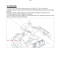
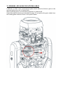
9.1- Safety cable
A safety cable must be securely fixed to the SYNERGY 5 SPOT and to the
suspension truss in order to avoid the fixture accidentally falling should the main fixing
point fail.
Make sure that the safety cable or chain can bear the weight of the entire unit.
A suitable safety cable is available on demand.
You may attach the safety cable to the attachment point (A) located on the base of the
fixture, as shown in the picture below.

13
9.2 Protection against liquids
The projector contains electric and electronic components which should under no
circumstances come into contact with oil, water or any other liquid.
The proper unit functioning would be compromised should this occur.
9.3- Movement
Pan: 540° rotation ; Tilt: 240° rotation.
Do not place any object in the path of the projector’s movement.
9.4- Risk of fire
Each fixture produces heat and must be installed in a well-ventilated place.
It is permissible to place the unit on normally flammable surfaces.
Suitable for mounting on normally flammable materials surfaces greater than 200°C
with some combustion time lag.
Minimum distance from the objects and the people lit by the light beam: 0,5 m.
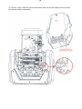
9.5- Forced ventilation
You will note, on inspection, that the unit features various air inlets and cooling fans
located on both the base and head of the fixture.
These should, under no circumstances, be blocked or obstructed whilst the projector
is in operation. Doing so could cause the fixture to seriously overheat thereby
compromising its proper operation.
9.6- Ambient temperature
The projector should never be installed in places that lack a constant air flow.
The ambient temperature should not exceed 40°C.
!

14
10- MAINS CONNECTION
SYNERGY 5 SPOT operates at 100-240Vac 50-60 Hz.
Prior to connecting the unit to your mains supply, ensure that the model in your
possession correctly matches the mains supply available.
For connection purposes, ensure that your plug is capable of supporting 3 amps
at 230Vac or 6,5 amps at 100Vac each unit connected.
Strict adherence to regulatory norms is strongly recommended.
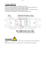
FUSE MAINS INPUT 100-240Vac 50-60 Hz
T 8A 250V PowerCon TRUE1 male panel connector
MAINS OUTPUT 100-240Vac 50-60 Hz (MAX 16A)
Max 4 SYNERGY 5 SPOT units @ 230Vac
Max 2 SYNERGY 5 SPOT units @ 100Vac
PowerCON TRUE1 female panel connector
10.1- Protection
The use of a thermal magnetic circuit breaker is recommended for each SYNERGY 5
SPOT.
A good earth connection is essential for the correct operation of the projector.
!

15
11- DMX SIGNAL CONNECTION
The unit operates using the digital DMX 512 signal.
Connection between the mixer and the projector or between projectors must be carried
out using a two pair screened ø 0.5 mm cable and a XLR 5 or 3 pins connector.
Ensure that the conductors do not touch each other.
Do not connect the cable ground to the XLR chassy.
The plug housing must be isolated. Connect the mixer signal to the DMX IN projector
plug and connect it to the next projector by connecting the DMX OUT plug on the first
projector to the DMX IN plug of the second one.
This way, all the projectors are cascade connected.
NB. If the display showing the DMX address flashes, then one of the following errors
has occurred:
- DMX signal not present
- DMX address not valid
- DMX reception problem
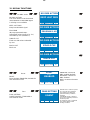
For Installations where long distance DMX cable connections are needed, we suggest
to use a DMX terminator.
The DMX terminator is a male XLR 3-5 pins connector with a 120 ohm resistor
between pin 2 and 3.
The DMX terminator must be plugged into the last unit (DMX out panel connector) of
the DMX line.
PLACE A 120 OHM RESISTOR BETWEEN PIN 2
AND 3 OF A MALE XRL CONNECTOR AND PLUG IT
INTO THE DMX OUT PANEL CONNECTOR OF THE
LAST UNIT CONNECTED TO THE DMX LINE
1
2
3
5
4
OUT
120 ohm
PIN 3
PIN 2

16
11.1-DMX Addresses
SYNERGY 5 SPOT can be controlled with 37 DMX channels.
In order to use the unit in 37 DMX channels mode, set the following addresses on the
mixer:
Projector 1 A001
Projector 2 A038 If you want to select the next projector, just add “37”
Projector 3 A075
….. A….
projector 6 A186
11.2-Selecting the DMX address
1) Press the UP-DOWN key until you reach the required DMX channel. The numbers
on the display will start to flash (but the new DMX address hasn't yet been set).
2) Press ENTER to confirm your selection. The numbers on the display will stop
flashing and the projector is now setted to the new DMX address.
TRICKS:
If you keep pushed the UP or DOWN keys, the channels are calculated more quickly
and you get a faster selection.

17
12- Art-Net / sACN SIGNAL CONNECTION
The unit operates using the Art-Net / sACN signal (sACN not yet implemented).
Connection between the mixer and the projector must be carried out using a category
5 network cable and a standard RJ45 connector.
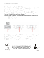
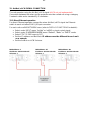
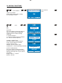
12.1-Direct Ethernet operation
For direct Ethernet operation connect the mixer Art-Net / sACN signal via Ethernet
switch to each unit etherCON RJ45 input connector.
For each unit scroll till NETWORK menu (refer to DISPLAY FUNCTIONS for details):
Select under INPUT menu “Art-Net” or “sACN” as input control signal.
Select under IP ADDRESS MODE menu “Default”, “Static” or “DHCP” mode.
Select ETH TO DMX menu to OFF.
Set the IP address and Net Mask. IP address must be different for each unit
on a network.
Set the Art-Net or sACN Universe.
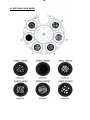
DMX address: 1 DMX address: 45 DMX address: 89
IP address: 002.214.192.007 IP address: 002.214.192.008 IP address: 002.214.192.009
Universe: 1 Universe: 1 Universe: 1

18
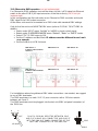
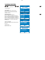
12.2-Ethernet to DMX operation (not yet implemented)
For Ethernet to DMX operation connect the mixer Art-Net / sACN signal via Ethernet
switch to the etherCON RJ45 input connector of the first unit only (sACN not yet
implemented).
In this configuration the first unit works as an Ethernet to DMX converter and sends
DMX signal to its DMX output connector.
All the other units must be connected as a DMX chain with standard DMX settings.
Only for the first unit scroll till NETWORK menu (refer to DISPLAY FUNCTIONS for
details):
Select under INPUT menu “Art-Net” or “sACN” as input control signal.
Select under IP ADDRESS MODE menu “Default”, “Static” or “DHCP” mode.
Select ETH TO DMX menu to ON.
Set the IP address and Net Mask. IP address must be different for each unit
on a network.
Set the Art-Net or sACN Universe.
DMX address: 1 DMX address: 45 DMX address: 89
IP address: 002.214.192.007
Universe: 1
DMX address: 1 DMX address: 45 DMX address: 89
IP address: 002.214.192.008
Universe: 2
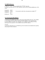
For Installations where long distance DMX cable connections are needed, we suggest
to use a DMX terminator.
The DMX terminator is a male XLR 3-5 pins connector with a 120 ohm resistor
between pin 2 and 3.
The DMX terminator must be plugged into the last unit (DMX out panel connector) of
the DMX line.
PLACE A 120 OHM RESISTOR BETWEEN PIN 2
AND 3 OF A MALE XRL CONNECTOR AND PLUG IT
INTO THE DMX OUT PANEL CONNECTOR OF THE
LAST UNIT CONNECTED TO THE DMX LINE
1
2
3
5
4
OUT
120 ohm
PIN 3
PIN 2

19
13- RDM FUNCTIONS
By using a RDM controller it is possible to read / set DMX address, DMX mode and
other parameters.
SYNERGY 5 SPOT accepts the following RDM commands:
SUPPORTED_PARAMETERS
List of all supported parameters
DEVICE_INFO
To read the following info:
RDM ID
Fixture type
Software version
DMX address
DMX mode
DMX channels
Total sensors
DEVICE_MODEL_DESCRIPTION
Fixture model
MANUFACTURER_LABEL
Manufacturer
SOFTWARE_VERSION_LABEL
Motors and LED Driver software version
DMX_PERSONALITY
To read / set the DMX mode
DMX_PERSONALITY_DESCRIPTION
Description / details of the DMX mode
DMX_START_ADDRESS
To read / set the DMX address
SENSOR_DEFINITION
List of sensors:
1: LED MODULE
LED temperature (°C).
2: LED DRIVER #1
White 1 and White 2 outputs of LED
Driver board temperature (°C).
3: LED DRIVER #2
White 3 and White 4 outputs of LED
Driver board temperature (°C).
4: MICRO
Micro controller temperature (°C).
5: DC SUPPLY
Power supply output voltage (48Vdc).
SENSOR_VALUE
To read / refresh the value of each sensor
DEVICE_HOURS
Fixture life time
LAMP_HOURS
LED life time
IDENTIFY_DEVICE
LED ON at max power to identify the
fixture
14- FIRMWARE UPDATING
To update the firmware release of the SYNERGY 5 SPOT you need:
- DTS Dongle Firmware Uploader (code 03.LA.206).
- “DTS Firmware Upgrade Utility v.2.02” program installed on PC.
- Latest firmware release available for SYNERGY 5 SPOT unit.
Updating the firmware release.
Please follow the procedure below to perform the update:
1. Connect the DTS Dongle Firmware Uploader to a spare USB port on the PC.
2. Connect the unit DMX input to the DTS Dongle Firmware Uploader DMX output with
a standard DMX cable and turn ON the unit.
3. Send the new firmware release into the unit by using “DTS Firmware Upgrade
Utility v.2.02” program. At the end of the procedure, the unit will reset.
For more information please refer to an authorised DTS service centre.

20
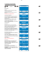
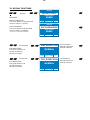
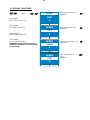
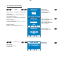
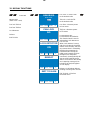
15- DISPLAY FUNCTIONS
The SYNERGY 5 SPOT display panel shows all the available functions. Using these
functions, it is possible to change some of the parameters and add some functions.
Changing the DTS setting can vary the functions of the unit so that it does not
respond to the DMX 512 used to control it. Carefully follow the instructions below
before carrying out any variations or selections.
NOTE: the symbol shows which key has to be pushed to obtain the desired
function.
MOTORS FIRMWARE RELEASE
10
RDM Device Model ID
0x0014
DMX Personality IDs
0x01 “37 CHANNELS”
La pagina si sta caricando...
La pagina si sta caricando...
La pagina si sta caricando...
La pagina si sta caricando...
La pagina si sta caricando...
La pagina si sta caricando...
La pagina si sta caricando...
La pagina si sta caricando...
La pagina si sta caricando...
La pagina si sta caricando...
La pagina si sta caricando...
La pagina si sta caricando...
La pagina si sta caricando...
La pagina si sta caricando...
La pagina si sta caricando...
La pagina si sta caricando...
La pagina si sta caricando...
La pagina si sta caricando...
La pagina si sta caricando...
La pagina si sta caricando...
La pagina si sta caricando...
La pagina si sta caricando...
La pagina si sta caricando...
La pagina si sta caricando...
La pagina si sta caricando...
La pagina si sta caricando...
La pagina si sta caricando...
La pagina si sta caricando...
La pagina si sta caricando...
La pagina si sta caricando...
La pagina si sta caricando...
La pagina si sta caricando...
-
 1
1
-
 2
2
-
 3
3
-
 4
4
-
 5
5
-
 6
6
-
 7
7
-
 8
8
-
 9
9
-
 10
10
-
 11
11
-
 12
12
-
 13
13
-
 14
14
-
 15
15
-
 16
16
-
 17
17
-
 18
18
-
 19
19
-
 20
20
-
 21
21
-
 22
22
-
 23
23
-
 24
24
-
 25
25
-
 26
26
-
 27
27
-
 28
28
-
 29
29
-
 30
30
-
 31
31
-
 32
32
-
 33
33
-
 34
34
-
 35
35
-
 36
36
-
 37
37
-
 38
38
-
 39
39
-
 40
40
-
 41
41
-
 42
42
-
 43
43
-
 44
44
-
 45
45
-
 46
46
-
 47
47
-
 48
48
-
 49
49
-
 50
50
-
 51
51
-
 52
52


DTS Synergy 5 Spot Manuale utente
- Categoria
- Proiettori
- Tipo
- Manuale utente
in altre lingue
- English: DTS Synergy 5 Spot User manual
Documenti correlati


Altri documenti
-
Cameo OPUS® SP5+ Manuale utente
-
-
-
Martin MAC 500E Manuale utente
-
CHAUVET DJ DMX-AN Guida di riferimento
-
ProLights RA2000PROFILE Manuale utente
-
-
-
-