Vetus Engine Control Panels MP'10'21'22'34' Guida d'installazione
- Tipo
- Guida d'installazione

Motorbedieningspanelen
Engine control panels
Motorarmaturenbrett
Tableaux de bord du moteur
Paneles de control del
motor
Pannelli di controllo
motore
Copyright © 2014 Vetus b.v. Schiedam Holland
Installatie instructies
Installation instructions
Installationsvorschriften
Instructions d’installation
Instrucciones de instalación
Istruzioni per l’installazione
NEDERLANDS 2
ENGLISH 3
DEUTSCH 4
FRANÇAIS 5
ESPAÑOL 6
ITALIANO 7
‘10’
‘21’
‘22’
‘34’
090421.03
La pagina si sta caricando...
La pagina si sta caricando...
La pagina si sta caricando...
La pagina si sta caricando...
La pagina si sta caricando...

090421.03 7
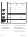
Pannelli di controllo motore
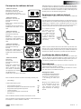
Descrizione dei pannelli
• Pannello per motore tipo ‘10’
Ingombro: 94 x 156 mm
Profondità di incastro: 120 mm
Nessun contatore
Comandi attraverso chiave estraibile
• Pannello per motore tipo ‘21’
Ingombro: 193 x 161 mm
Profondità di incastro: 120 mm
Provvisto di un contatore di giri/
contatore a tempo
Possibilità di inserimento di un vol-
tametro
Comandi attraverso chiave estrai-
bile
• Pannello per motore tipo ‘22’
Ingombro: 193 x 161 mm
Profondità di incastro: 120 mm
Provvisto di un contatore di giri/
contatore a tempo e di un volta-
metro
Comandi attraverso chiave estrai-
bile
• Pannello per motore tipo A22’
Ingombro: 218 x 156 mm
Profondità di incastro: 120 mm
Provvisto di un contatore di giri/
contatore a tempo e di un volta-
metro
Comandi attraverso chiave estrai-
bile
• Pannello per motore tipo
‘34’
Ingombro: 255 x 161 mm
Profondità di incastro:
120mm
Provvisto di contatore di
giri/contatore a tempo,
voltametro, manometro
dell’olio e rilevatore
di temperatura del liquido di raffreddamento.
Comandi attraverso chiave estraibile
Tutti i pannelli sono dotati di una spia luminosa per:
• accensionediavviamento
e una spia di segnalazione per
• pressionedell’olioinsufficiente
• temperaturadelliquidodiraffreddamentoelevata
• temperaturadiscaricoelevata
• correntedicaricamento
• pressionedell’oliodell’inversionedimarciainsufficiente (non
sui modelli tipo ‘10’)
Tutti i pannelli sono dotati di un allarme sonoro.
Tutti i pannelli possono essere utilizzati sia come primi o unici pan-
nelli che come secondi pannelli.
N.B.: Quando l’allarme si attiva, spetta al responsabile dell’imbarca-
zione la scelta tra arrestare il motore e diminuire il suo numero di giri.
In motori a propulsione non è raccomandabile applicare un sistema
aatraverso il quale, in caso di attivazione dell’allarme, il motore si
arresta automaticamente. Si potrebbero infatti verificare situazioni
pericolose qualora il motore subisse un arresto improvviso in deter-
minate circostanze.
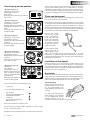
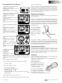
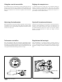
Collocazione del pannello
Collocare il pannello del motore sempre in una posizione facilmente
accessibile al controllo visivo da parte del responsabile dell’imbar-
cazione.
Il pannello del motore può essere collocato anche all’esterno; in tal
caso sarà tuttavia indispensabile installare il cappuccio di chiusura
impermeabile (destinato alla serratura della chiavetta di avviamen-
to) fornito con l’articolo. Questo cappuccio impedisce infatti che
acqua, sale e scorie penetrino nella serratura quando la chiavetta è
disinserita. Qualora si applichi un dispositivo di protezione su tutto il
pannello del motore, non risulterà necessario applicare il cappuccio
di chiusura.
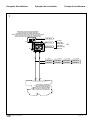
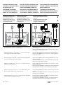
Quando il pannello del
motore viene installato
ad un livello basso dello
scafo, occorre posizio-
narlo in modo tale (cfr.
illustrazione) che nes-
sun danno possa essere
apportato alla chiave
(a causa per esempio
di urti involontari con
i piedi).
Accertarsi che il pannello del motore sia impermeabile all’acqua
soltanto dalla parte dei comandi. La parte posteriore del pannello
del motore deve essere installata in un ambiente ben protetto e
ventilato. Eseguire l’installazione in una posizione in cui il pannello
non possa essere sottoposto a forti vibrazioni.
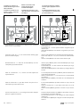
Installazione del pannello
Il pannello deve essere collocato in una parete di separazione.
Praticare in tale parete un foro delle giuste dimensioni. Montare il
pannello con l’ausilio delle 4 viti incluse nella confezione e utilizzan-
do lo stampo di riferimento fornito insieme all’articolo. Assicurarsi
che la guarnizione venga posizionata correttamente tra il pannello
del motore e la parete di separazione.
Collegamento
Collegare i cavi universali del motore (2 o 3) con i componenti elet-
trici del motore. Consultare lo schema.
Collegare quindi il pannello del motore con i cavi del motore inse-
rendo i collegamenti di giunzione l’uno nell’altro (2 o 3).
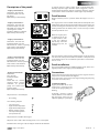
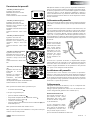
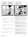
Illuminazione della scala
Nei pannelli provvisti di uno o
più contatori, nel filo + dell’il-
luminazione della scala è stato
inserito un ulteriore collegamen-
to, cfr. illustrazione.
Su tale collegamento supple-
mentare è possibile, se lo si desi-
dera, collocare un interruttore o
un dipswitch (a corrente conti-
nua), in modo da poter variare a
piacere l’intensità di illuminazione della scala.
ITALIANO

8 090421.03
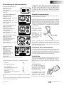
Engine control panels
Installatievoorbeelden Installation examples Installationsbeispiele
Installatievoorbeeld 1
Schema voor:
- Alle Vetus-motoren. NB: voor M2, M3, M4 en VH4 alleen 12 volt!
- Niet-Vetus motoren met standaard in het motorblok een schakel-
contact voor te hoge temperatuur en een schakelcontact voor te
lage oliedruk, beide voor het bedienen van een waarschuwings-
lamp.
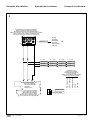
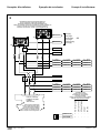
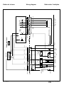
Installation example 1
Diagram for:
- All Vetus engines. Note: for M2, M3, M4 and VH4 only 12 Volt!
- Non-Vetus engines with a high coolant temperature switch and a
low oil pressure switch, both to operate a warning light, installed
into the engine block.
Installationsbeispiel 1
Schaltplan für:
- Alle Vetus-Motoren. Hinweis: für M2, M3, M4 und VH4 nur 12
Volt!
- Nicht von Vetus stammende Motoren mit einem Schaltkontakt
für zu hohe Temperaturen und einem Schaltkontakt für zu
niedrigen Öldruck als Standard im Motorblock – beide für die
Bedienung einer Warnlampe.
Exemple d’installation 1
Diagramme pour :
- Tous les moteurs Vetus. Remarque : pour M2, M3, M4 et VH4, 12
volts uniquement !
- Moteurs d’une autre marque que Vetus équipés en standard dans
le bloc-moteur d’un contacteur pour températures trop élevées
et d’un contacteur pour pression d’huile trop basse, les deux
contacteurs étant reliés à un témoin lumineux.
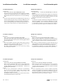
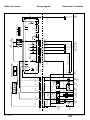
Esempio di installazione 1
Schema per:
- Tutti i motori Vetus. Nota: per M2, M3, M4 e VH4 solo 12 Volt!
- Motori non Vetus con blocco motore dotato di serie di interrut-
tore di sicurezza contro il surriscaldamento e di interruttore di
sicurezza contro una pressione troppo bassa dell’olio, entrambi
collegati ad una spia luminosa.
Ejemplo de instalación 1
Esquema para:
- Todos los motores Vetus. Nota: ¡para M2, M3, M4 y VH4 sólo 12
voltios!
- Motores no Vetus equipados en estándar con interruptor de tem-
peratura refrigerante alta e interruptor de presión de aceite baja,
ambos accionadores de luz de aviso, en el bloque del motor.

090421.03 9
Engine control panels
A B
A
B
MPKA02
MPKB02
MPKA04 MPKA06
MPKB04 MPKB06
L = 2 m L = 4 m L = 6 m
MPKA12
MPKB12
L = 12 m
'22'
'21'
'10'
MP10B12
MP21xxxxx
MP22xxxxx
Motor inclusief motorbedrading
Engine complete with engine wiring
Motor inklusive Motorverkablung
Moteur fourni complet avec câblage
Motor completo con cableado de motor
Motore completo di cavi di collegamento
Motorbedieningspaneel inclusief paneelbedrading
Engine control panel complete with panel wiring
Motorarmaturenbrett inklusive Armaturenbrettverkabelung
Tableau de commande du moteur fourni complet avec panneau de câblage
Panel de control del motor completo con cableado de panel
Pannello di controllo motore completo di cavi di collegamento
zie pag.
see page
siehe Seite
voir page
véase la pág.
vedi pag.
28
1
Exemples d’installation Ejemplos de instalación Esempi di installazione

10 090421.03
Engine control panels
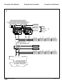
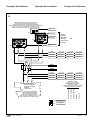
Installation example 2
Diagram for:
- Vetus engines: M2, M3, M4, VH4. Note: only 12 Volt!
- Non-Vetus engines with a high coolant temperature switch and a
low oil pressure switch, both to operate a warning light, installed
into the engine block.
Note:
- The panel installed connection cables (X2->B and X3->C) have
to be replaced by an interface [STM 6911] and an interface cable
[MPVB2], see installation instruction, page 24.
- The engine installed switches have to be replaced by sending
units for display instruments.
Installatievoorbeeld 2
Schema voor:
- Vetus-motoren: M2, M3, M4, VH4. NB: alleen 12 volt!
- Niet-Vetus motoren met standaard in het motorblok een schakel-
contact voor te hoge temperatuur en een schakelcontact voor te
lage oliedruk, beide voor het bedienen van een waarschuwings-
lamp.
NB:
- De op het paneel geïnstalleerde aansluitkabels (X2->B en X3->C)
moeten worden vervangen door een interface [STM 6911] en een
interfacekabel [MPVB2]; zie installatieaanwijzing, bladzijde 24.
- De in de motor geïnstalleerde schakelaars moeten worden ver-
vangen door zendereenheden voor dashboardinstrumenten.
Installationsbeispiel 2
Schaltplan für:
- Vetus-Motoren: M2, M3, M4, VH4. Hinweis: nur 12 Volt!
- Nicht von Vetus stammende Motoren mit einem Schaltkontakt
für zu hohe Temperaturen und einem Schaltkontakt für zu
niedrigen Öldruck als Standard im Motorblock – beide für die
Bedienung einer Warnlampe.
Hinweis:
- Die auf dem Armaturenbrett installierten Anschlusskabel
(X2->B und X3->C) müssen durch einen Interface [STM
6911] und ein Interfacekabel [MPVB2] ersetzt werden; siehe
Installationsvorschriften, Seite 24.
- Die im Motor installierten Schalter müssen durch Sendereinheiten
für Schalttafelinstrumente ersetzt werden.
Exemple d’installation 2
Diagramme pour :
- Les moteurs Vetus : M2, M3, M4, VH4. Remarque : 12 volts seu-
lement !
- Moteurs d’une autre marque que Vetus équipés en standard dans
le bloc-moteur d’un contacteur pour températures trop élevées
et d’un contacteur pour pression d’huile trop basse, les deux
contacteurs étant reliés à un témoin lumineux.
Remarque :
- Les câbles de connexion installés sur le tableau (X2->B et X3->C)
doivent être remplacés par une interface [STM 6911] et un câble
d’interface [MPVB2] ; voir les instructions d’installation, page 24.
- Les interrupteurs installés sur le moteur doivent être remplacés
par des contacteurs (sensors) pour les instruments de contrôle.
Ejemplo de instalación 2
Esquema para:
- Motores Vetus: M2, M3, M4, VH4. Nota: ¡Sólo 12 voltios!
- Motores no Vetus equipados en estándar con interruptor de tem-
peratura refrigerante alta e interruptor de presión de aceite baja,
ambos accionadores de luz de aviso, en el bloque del motor.
Nota:
- Los cables de conexión instalados en el panel (X2->B y X3->C)
deben sustituirse por una interfaz [STM 6911] y un cable de inter-
faz [MPVB2], vea las instrucciones de instalación, página 24.
- Los interruptores instalados en el motor deben sustituirse por
unidades de transmisión para instrumentos de visualización.
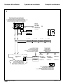
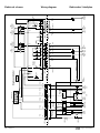
Esempio di installazione 2
Schema per:
- Motori Vetus: M2, M3, M4, VH4. Nota: solo 12 Volt!
- Motori non Vetus con blocco motore dotato di serie di interrut-
tore di sicurezza contro il surriscaldamento e di interruttore di
sicurezza contro una pressione troppo bassa dell’olio, entrambi
collegati ad una spia luminosa.
Nota:
- I cavi di collegamento (X2->B e X3->C), installati sul pannello,
devono essere sostituiti con un’interfaccia [STM 6911] ed un cavo
di interfaccia [MPVB2], vedi istruzioni di installazione, pagina 24.
- Gli interruttori installati sul motore devono essere sostituiti da
dispositivi di trasmissione per strumenti a display.
Installatievoorbeelden Installation examples Installationsbeispiele

090421.03 11
Engine control panels
A
X4X3
X2
X6X5
STM6911
B B
MPVB2
MP34xxxxx
M2, M3, M4
VH4
STM8326 =
TEMPSR120
CT40083 =
OILSR08
MPKA02
MPKB02
MPKA04 MPKA06
MPKB04 MPKB06
L = 2 m L = 4 m L = 6 m
MPKA12
MPKB12
L = 12 m
'34'
A B
B
X2
C
X3
M2/M3:
AD14-16
+ STM1062
+ STM7953
STM6341
M4:
AD14-16
+ STM1062
+ STM7953
STM7581
Motorbedieningspaneel inclusief paneelbedrading
Engine control panel complete with panel wiring
Motorarmaturenbrett inklusive Armaturenbrettverkabelung
Tableau de commande du moteur fourni complet avec panneau de câblage
Panel de control del motor completo con cableado de panel
Pannello di controllo motore completo di cavi di collegamento
Motor inclusief motorbedrading
Engine complete with engine wiring
Motor inklusive Motorverkablung
Moteur fourni complet avec câblage
Motor completo con cableado de motor
Motore completo di cavi di collegamento
Te installeren zenders
Sending units to be installed
Zu installierende Sendereinheiten
Contacteurs à installer
Unidades de transmisión que deben instalarse
Dispositivi di trasmissione da installare
Benodigde adapters
Required adapters
Benötigte Adapter
Adaptateurs nécessaires
Adaptadores necesarios
Adattatori richiesti
Temperatuurschakelaar en oliedrukschakelaar
Temp. switch and oil pressure switch
Temperaturschalter und Öldruckschalter
Interrupteur de température et de pression d’huile
Interruptor de temperatura e interruptor de presión de aceite
Interruttore termico e pressostato dell’olio
VH4:
STM1062
STM7581
zie pag.
see page
siehe Seite
voir page
véase la pág.
vedi pag.
28
2
Exemples d’installation Ejemplos de instalación Esempi di installazione

12 090421.03
Engine control panels
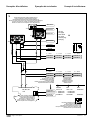
Installation example 3
Diagram for:
- Vetus engines: DT4.70, DTA4.85, DT(A)44, DT(A)66, DT(A)67, VF4
and VF5.
- Non-Vetus engines with a high coolant temperature switch and a
low oil pressure switch, both to operate a warning light, installed
into the engine block and the posibility to install, both for oil
pressure and coolant temperature, sending units for display
instruments.
Installatievoorbeeld 3
Schema voor:
- Vetus-motoren: DT4.70, DTA4.85, DT(A)44, DT(A)66, DT(A)67, VF4
en VF5.
- Niet-Vetus motoren met standaard in het motorblok een schakel-
contact voor te hoge temperatuur en een schakelcontact voor te
lage oliedruk, beide voor het bedienen van een waarschuwings-
lamp, en de mogelijkheid om voor zowel oliedruk als tempera-
tuur een gever voor een meter te monteren.
Installationsbeispiel 3
Schaltplan für:
- Vetus-Motoren: DT4.70, DTA4.85, DT(A)44, DT(A)66, DT(A)67, VF4
undVF5.
- Nicht von Vetus stammende Motoren mit einem Schaltkontakt
für zu hohe Temperaturen und einem Schaltkontakt für zu
niedrigen Öldruck als Standard im Motorblock – beide für die
Bedienung einer Warnlampe – und die Möglichkeit, sowohl für
den Öldruck als auch die Temperatur einen Messgeber zu instal-
lieren.
Exemple d’installation 3
Diagramme pour :
- Les moteurs Vetus : DT4.70, DTA4.85, DT(A)44, DT(A)66, DT(A)67,
VF4 et VF5.
- Moteurs d’une autre marque que Vetus équipés en standard dans
le bloc-moteur d’un contacteur pour températures trop élevées
et d’un contacteur pour pression d’huile trop basse, les deux
contacteurs étant reliés à un témoin lumineux, et avec la possibi-
lité d’installer un indicateur de mesure tant pour la température
trop élevée que pour la pression d’huile trop basse.
Ejemplo de instalación 3
Esquema para:
- Motores Vetus: DT4.70, DTA4.85, DT(A)44, DT(A)66, DT(A)67, VF4 y
VF5.
- Motores no Vetus equipados en estándar con interruptor de tem-
peratura refrigerante alta e interruptor de presión de aceite baja,
ambos accionadores de luz de aviso, en el bloque del motor, y la
posibilidad de instalar, tanto para la presión de aceite como para
la temperatura de refrigerante, unidades de transmisión para
instrumentos de visualización.
Esempio di installazione 3
Schema per:
- Motori Vetus: DT4.70, DTA4.85, DT(A)44, DT(A)66, DT(A)67, VF4 e
VF5.
- Motori non Vetus con blocco motore dotato di serie di interrut-
tore di sicurezza contro il surriscaldamento e di interruttore di
sicurezza contro una pressione troppo bassa dell’olio, entrambi
collegati ad una spia luminosa e con possibilità di montaggio di
un trasmettitore, collegabile ad un misuratore sia della tempera-
tura, sia della pressione dell’olio.
Installatievoorbeelden Installation examples Installationsbeispiele

090421.03 13
Engine control panels
A B C
MP34xxxxx
MPKA02
MPKB02
MPKA04 MPKA06
MPKB04 MPKB06
L = 2 m L = 4 m L = 6 m
MPKA12
MPKB12
L = 12 m
MPKC02
MPKC04 MPKC06
MPKC12
'34'
A B C
Motorbedieningspaneel inclusief paneelbedrading
Engine control panel complete with panel wiring
Motorarmaturenbrett inklusive Armaturenbrettverkabelung
Tableau de commande du moteur fourni complet avec panneau de câblage
Panel de control del motor completo con cableado de panel
Pannello di controllo motore completo di cavi di collegamento
Motor inclusief motorbedrading
Engine complete with engine wiring
Motor inklusive Motorverkablung
Moteur fourni complet avec câblage
Motor completo con cableado de motor
Motore completo di cavi di collegamento
TEMPSR120
OILSR08
Non -Vetus engines
1 – – – –
1 – – – –
Te installeren zenders
Sending units to be installed
Zu installierende Sendereinheiten
Contacteurs à installer
Unidades de transmisión que deben instalarse
Dispositivi di trasmissione da installare
zie pag.
see page
siehe Seite
voir page
véase la pág.
vedi pag.
28
DT4.70, DTA4.85
DT(A)44, DT(A)66
DT(A)67
VF4 en VF5
DT4.70, DTA4.85
DT(A)44, DT(A)66
DT(A)67
VF4, VF5
3
Exemples d’installation Ejemplos de instalación Esempi di installazione

14 090421.03
Engine control panels
Installation example 4
Diagram for:
- All Vetus engines. Note: for M2, M3, M4 and VH4 only 12 Volt!
- Non-Vetus engines with a high coolant temperature switch and a
low oil pressure switch, both to operate a warning light, installed
into the engine block.
Installatievoorbeeld 4
Schema voor:
- Alle Vetus-motoren. NB: voor M2, M3, M4 en VH4 alleen 12 volt!
- Niet-Vetus motoren met standaard in het motorblok een schakel-
contact voor te hoge temperatuur en een schakelcontact voor te
lage oliedruk, beide voor het bedienen van een waarschuwings-
lamp.
Installationsbeispiel 4
Schaltplan für:
- Alle Vetus-Motoren. Hinweis: für M2, M3, M4 und VH4 nur 12
Volt!
- Nicht von Vetus stammende Motoren mit einem Schaltkontakt
für zu hohe Temperaturen und einem Schaltkontakt für zu
niedrigen Öldruck als Standard im Motorblock – beide für die
Bedienung einer Warnlampe.
Exemple d’installation 4
Diagramme pour :
- Tous les moteurs Vetus. Remarque : pour M2, M3, M4 et VH4, 12
volts uniquement !
- Moteurs d’une autre marque que Vetus équipés en standard dans
le bloc-moteur d’un contacteur pour températures trop élevées
et d’un contacteur pour pression d’huile trop basse, les deux
contacteurs étant reliés à un témoin lumineux.
Ejemplo de instalación 4
Esquema para:
- Todos los motores Vetus. Nota: ¡para M2, M3, M4 y VH4 sólo 12
voltios!
- Motores no Vetus equipados en estándar con interruptor de tem-
peratura refrigerante alta e interruptor de presión de aceite baja,
ambos accionadores de luz de aviso, en el bloque del motor.
Esempio di installazione 4
Schema per:
- Tutti i motori Vetus. Nota: per M2, M3, M4 e VH4 solo 12 Volt!
- Motori non Vetus con blocco motore dotato di serie di interrut-
tore di sicurezza contro il surriscaldamento e di interruttore di
sicurezza contro una pressione troppo bassa dell’olio, entrambi
collegati ad una spia luminosa.
Installatievoorbeelden Installation examples Installationsbeispiele

090421.03 15
Engine control panels
A
A A B B
B
A B
MPYB
MPYA
A B
A B
MPKA02
MPKB02
MPKA04 MPKA06
MPKB04 MPKB06
L = 2 m L = 4 m L = 6 m
MPKA12
MPKB12
L = 12 m
MPKA02
MPKB02
MPKA04 MPKA06
MPKB04 MPKB06
L = 2 m L = 4 m L = 6 m
MPKA12
MPKB12
L = 12 m
'22'
'21'
'10'
MP10B12
MP21xxxxx
MP22xxxxx
Motorbedieningspaneel inclusief paneelbedrading (2x)
Engine control panel complete with panel wiring (2x)
Motorarmaturenbrett inklusive Armaturenbrettverkabelung (2x)
Tableau de commande du moteur fourni complet avec panneau de câblage (2x)
Panel de control del motor completo con cableado de panel (2x)
Pannello di controllo motore completo di cavi di collegamento (2x)
Motor inclusief motorbedrading
Engine complete with engine wiring
Motor inklusive Motorverkablung
Moteur fourni complet avec câblage
Motor completo con cableado de motor
Motore completo di cavi di collegamento
zie pag.
see page
siehe Seite
voir page
véase la pág.
vedi pag.
28
4
Exemples d’installation Ejemplos de instalación Esempi di installazione

16 090421.03
Engine control panels
Installation example 5
Diagram for:
- Vetus engines: M2, M3, M4, VH4. Note: only 12 Volt!
- Non-Vetus engines with a high coolant temperature switch and a
low oil pressure switch, both to operate a warning light, installed
into the engine block.
Note:
- The panel installed connection cables (X2->B and X3->C) have
to be replaced by an interface [STM 6911] and an interface cable
[MPVB2], see installation instruction, page 24.
- The engine installed switches have to be replaced by sending
units for display instruments.
Installatievoorbeeld 5
Schema voor:
- Vetus-motoren: M2, M3, M4, VH4. NB: alleen 12 volt!
- Niet-Vetus motoren met standaard in het motorblok een schakel-
contact voor te hoge temperatuur en een schakelcontact voor te
lage oliedruk, beide voor het bedienen van een waarschuwings-
lamp.
NB:
- De op het paneel geïnstalleerde aansluitkabels (X2->B en X3->C)
moeten worden vervangen door een interface [STM 6911] en een
interfacekabel [MPVB2]; zie installatieaanwijzing, bladzijde 24.
- De in de motor geïnstalleerde schakelaars moeten worden ver-
vangen door zendereenheden voor dashboardinstrumenten.
Installationsbeispiel 5
Schaltplan für:
- Vetus-Motoren: M2, M3, M4, VH4. Hinweis: nur 12 Volt!
- Nicht von Vetus stammende Motoren mit einem Schaltkontakt
für zu hohe Temperaturen und einem Schaltkontakt für zu
niedrigen Öldruck als Standard im Motorblock – beide für die
Bedienung einer Warnlampe.
Hinweis:
- Die auf dem Armaturenbrett installierten Anschlusskabel
(X2->B und X3->C) müssen durch einen Interface [STM
6911] und ein Interfacekabel [MPVB2] ersetzt werden; siehe
Installationsvorschriften, Seite 24.
- Die im Motor installierten Schalter müssen durch Sendereinheiten
für Schalttafelinstrumente ersetzt werden.
Exemple d’installation 5
Diagramme pour :
- Les moteurs Vetus : M2, M3, M4, VH4. Remarque : 12 volts seu-
lement !
- Moteurs d’une autre marque que Vetus équipés en standard dans
le bloc-moteur d’un contacteur pour températures trop élevées
et d’un contacteur pour pression d’huile trop basse, les deux
contacteurs étant reliés à un témoin lumineux.
Remarque :
- Les câbles de connexion sur le tableau (X2->B et X3->C) doivent
être remplacés par une interface [STM 6911] et un câble d’inter-
face [MPVB2] ; voir les instructions d’installation, page 24.
- Les interrupteurs installés sur le moteur doivent être remplacés
par des contacteurs destinés aux instruments de contrôle.
Ejemplo de instalación 5
Esquema para:
- Motores Vetus: M2, M3, M4, VH4. Nota: ¡Sólo 12 voltios!
- Motores no Vetus equipados en estándar con interruptor de tem-
peratura refrigerante alta e interruptor de presión de aceite baja,
ambos accionadores de luz de aviso, en el bloque del motor.
Nota:
- Los cables de conexión instalados en el panel (X2->B y X3->C)
deben sustituirse por una interfaz [STM 6911] y un cable de inter-
faz [MPVB2], vea las instrucciones de instalación, página 24.
- Los interruptores instalados en el motor deben sustituirse por
unidades de transmisión para instrumentos de visualización.
Esempio di installazione 5
Schema per:
- Motori Vetus: M2, M3, M4, VH4. Nota: solo 12 Volt!
- Motori non Vetus con blocco motore dotato di serie di interrut-
tore di sicurezza contro il surriscaldamento e di interruttore di
sicurezza contro una pressione troppo bassa dell’olio, entrambi
collegati ad una spia luminosa.
Nota:
- I cavi di collegamento (X2->B e X3->C), installati sul pannello,
devono essere sostituiti con un’interfaccia [STM 6911] ed un cavo
di interfaccia [MPVB2], vedi istruzioni di installazione, pagina 24.
- Gli interruttori installati sul motore devono essere sostituiti da
dispositivi di trasmissione per strumenti a display.
Installatievoorbeelden Installation examples Installationsbeispiele

090421.03 17
Engine control panels
A
X4
X3
X2
X6X5
STM6911
B B
MPVB2
A
A A
B
A B
MPYA
A
B
MPKA02
MPKB02
MPKA04 MPKA06
MPKB04 MPKB06
L = 2 m L = 4 m L = 6 m
MPKA12
MPKB12
L = 12 m
MPKA02
MPKB02
MPKA04 MPKA06
MPKB04 MPKB06
L = 2 m L = 4 m L = 6 m
MPKA12
MPKB12
L = 12 m
MP34xxxxx
M2, M3, M4
VH4
X4
'22'
'21'
'10'
'34'
MP10B12
MP21xxxxx
MP22xxxxx
B
X2
C
X3
STM8326 =
TEMPSR120
CT40083 =
OILSR08
Motorbedieningspaneel inclusief paneelbedrading (2x)
Engine control panel complete with panel wiring (2x)
Motorarmaturenbrett inklusive Armaturenbrettverkabelung (2x)
Tableau de commande du moteur fourni complet avec panneau de câblage (2x)
Panel de control del motor completo con cableado de panel (2x)
Pannello di controllo motore completo di cavi di collegamento (2x)
Motor inclusief motorbedrading
Engine complete with engine wiring
Motor inklusive Motorverkablung
Moteur fourni complet avec câblage
Motor completo con cableado de motor
Motore completo di cavi di collegamento
Temperatuurschakelaar en oliedrukschakelaar
Temp. switch and oil pressure switch
Temperaturschalter und Öldruckschalter
Interrupteur de température et de pression d’huile
Interruptor de temperatura e interruptor de presión de aceite
Interruttore termico e pressostato dell’olio
M2/M3:
AD14-16
+ STM1062
+ STM7953
STM6341
M4:
AD14-16
+ STM1062
+ STM7953
STM7581
Te installeren zenders
Sending units to be installed
Zu installierende Sendereinheiten
Contacteurs à installer
Unidades de transmisión que deben instalarse
Dispositivi di trasmissione da installare
Benodigde adapters
Required adapters
Benötigte Adapter
Adaptateurs nécessaires
Adaptadores necesarios
Adattatori richiesti
VH4:
STM1062
STM7581
zie pag.
see page
siehe Seite
voir page
véase la pág.
vedi pag.
28
5
Exemples d’installation Ejemplos de instalación Esempi di installazione

18 090421.03
Engine control panels
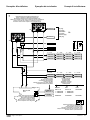
Installation example 6
Diagram for:
- Vetus engines: DT4.70, DTA4.85, DT(A)44, DT(A)66, DT(A)67, VF4
and VF5.
- Non-Vetus engines with a high coolant temperature switch and a
low oil pressure switch, both to operate a warning light, installed
into the engine block and the posibility to install, both for oil
pressure and coolant temperature, sending units for display
instruments.
Installatievoorbeeld 6
Schema voor:
- Vetus-motoren: DT4.70, DTA4.85, DT(A)44, DT(A)66, DT(A)67, VF4
en VF5.
- Niet-Vetus motoren met standaard in het motorblok een schakel-
contact voor te hoge temperatuur en een schakelcontact voor te
lage oliedruk, beide voor het bedienen van een waarschuwings-
lamp, en de mogelijkheid om voor zowel oliedruk als tempera-
tuur een gever voor een meter te monteren.
Installationsbeispiel 6
Schaltplan für:
- Vetus-Motoren: DT4.70, DTA4.85, DT(A)44, DT(A)66, DT(A)67, VF4
und VF5.
- Nicht von Vetus stammende Motoren mit einem Schaltkontakt
für zu hohe Temperaturen und einem Schaltkontakt für zu
niedrigen Öldruck als Standard im Motorblock – beide für die
Bedienung einer Warnlampe – und die Möglichkeit, sowohl für
den Öldruck als auch die Temperatur einen Messgeber zu instal-
lieren.
Exemple d’installation 6
Diagramme pour :
- Les moteurs Vetus : DT4.70, DTA4.85, DT(A)44, DT(A)66, DT(A)67,
VF4 et VF5.
- Moteurs d’une autre marque que Vetus équipés en standard dans
le bloc-moteur d’un contacteur pour températures trop élevées
et d’un contacteur pour pression d’huile trop basse, les deux
contacteurs étant reliés à un témoin lumineux, et avec la possibi-
lité d’installer un indicateur de mesure tant pour la température
trop élevée que pour la pression d’huile trop basse.
Ejemplo de instalación 6
Esquema para:
- Motores Vetus: DT4.70, DTA4.85, DT(A)44, DT(A)66, DT(A)67, VF4 y
VF5.
- Motores no Vetus equipados en estándar con interruptor de tem-
peratura refrigerante alta e interruptor de presión de aceite baja,
ambos accionadores de luz de aviso, en el bloque del motor, y la
posibilidad de instalar, tanto para la presión de aceite como para
la temperatura de refrigerante, unidades de transmisión para
instrumentos de visualización.
Esempio di installazione 6
Schema per:
- Motori Vetus: DT4.70, DTA4.85, DT(A)44, DT(A)66, DT(A)67, VF4 e
VF5.
- Motori non Vetus con blocco motore dotato di serie di interrut-
tore di sicurezza contro il surriscaldamento e di interruttore di
sicurezza contro una pressione troppo bassa dell’olio, entrambi
collegati ad una spia luminosa e con possibilità di montaggio di
un trasmettitore, collegabile ad un misuratore sia della tempera-
tura, sia della pressione dell’olio.
Installatievoorbeelden Installation examples Installationsbeispiele

090421.03 19
Engine control panels
A
X4
B C
A
A A
B
A B
MPYB
A
B
MPKA02
MPKB02
MPKA04 MPKA06
MPKB04 MPKB06
L = 2 m L = 4 m L = 6 m
MPKA12
MPKB12
L = 12 m
MP34xxxxx
MPYA
B B
C
MPKC02
MPKC04 MPKC06
MPKC12
MPKA02
MPKB02
MPKA04 MPKA06
MPKB04 MPKB06
L = 2 m L = 4 m L = 6 m
MPKA12
MPKB12
L = 12 m
MPKC02
MPKC04 MPKC06
MPKC12
'22'
'21'
'10'
'34'
MP10B12
MP21xxxxx
MP22xxxxx
TEMPSR120
OILSR08
Te installeren zenders
Sending units to be installed
Zu installierende Sendereinheiten
Contacteurs à installer
Unidades de transmisión que deben instalarse
Dispositivi di trasmissione da installare
Motorbedieningspaneel inclusief paneelbedrading (2x)
Engine control panel complete with panel wiring (2x)
Motorarmaturenbrett inklusive Armaturenbrettverkabelung (2x)
Tableau de commande du moteur fourni complet avec panneau de câblage (2x)
Panel de control del motor completo con cableado de panel (2x)
Pannello di controllo motore completo di cavi di collegamento (2x)
Motor inclusief motorbedrading
Engine complete with engine wiring
Motor inklusive Motorverkablung
Moteur fourni complet avec câblage
Motor completo con cableado de motor
Motore completo di cavi di collegamento
zie pag.
see page
siehe Seite
voir page
véase la pág.
vedi pag.
28
DT4.70, DTA4.85
DT(A)44, DT(A)66
DT(A)67
VF4 en VF5
Non -Vetus engines
1 – – – –
1 – – – –
DT4.70, DTA4.85
DT(A)44, DT(A)66
DT(A)67
VF4, VF5
6
Exemples d’installation Ejemplos de instalación Esempi di installazione

20 090421.03
Engine control panels
Installation example 7
Diagram for:
- Vetus engines: M2, M3, M4, VH4. Note: only 12 Volt!
- Non-Vetus engines with a high coolant temperature switch and a
low oil pressure switch, both to operate a warning light, installed
into the engine block.
Note:
- On one (1) panel the installed connection cable (X2->B) have to
be replaced by an interface [STM 6911] and two interface cable
[MPVB2], [MPVC2], see installation instruction, page 25.
- The engine installed switches have to be replaced by sending
units for display instruments.
Installatievoorbeeld 7
Schema voor:
- Vetus-motoren: M2, M3, M4, VH4. NB: alleen 12 volt!
- Niet-Vetus motoren met standaard in het motorblok een schakel-
contact voor te hoge temperatuur en een schakelcontact voor te
lage oliedruk, beide voor het bedienen van een waarschuwings-
lamp.
NB:
- Op een (1) paneel moet de geïnstalleerde aansluitkabel (X2->B)
worden vervangen door een interface [STM 6911] en twee inter-
facekabels [MPVB2], [MPVC2]; zie installatieaanwijzing, bladzijde
25.
- De in de motor geïnstalleerde schakelaars moeten worden ver-
vangen door zendereenheden voor dashboardinstrumenten.
Installationsbeispiel 7
Schaltplan für:
- Vetus-Motoren: M2, M3, M4, VH4. Hinweis: nur 12 Volt!
- Nicht von Vetus stammende Motoren mit einem Schaltkontakt
für zu hohe Temperaturen und einem Schaltkontakt für zu
niedrigen Öldruck als Standard im Motorblock – beide für die
Bedienung einer Warnlampe.
Hinweis:
- Das auf dem Armaturenbrett (1) installierte Anschlusskabel
(X2->B) muss durch einen Interface [STM 6911] und zwei
Interfacekabel [MPVB2, [MPVC2]] ersetzt werden; siehe
Installationsvorschriften, Seite 25.
- Die im Motor installierten Schalter müssen durch Sendereinheiten
für Schalttafelinstrumente ersetzt werden.
Exemple d’installation 7
Diagramme pour :
- Les moteurs Vetus : M2, M3, M4, VH4. Remarque : 12 volts uni-
quement !
- Moteurs d’une autre marque que Vetus équipés en standard dans
le bloc-moteur d’un contacteur pour températures trop élevées
et d’un contacteur pour pression d’huile trop basse, les deux
contacteurs étant reliés à un témoin lumineux.
Remarque :
- Sur un tableau (1) le câble de connexion (X2->B) doit être rem-
placé par une interface [STM 6911] et deux câbles d’interface
[MPVB2], [MPVC2] ; voir les instructions d’installation, page 25.
- Les interrupteurs installés sur le moteur doivent être remplacés
par des contacteurs pour les instruments de contrôle.
Ejemplo de instalación 7
Esquema para:
- Motores Vetus: M2, M3, M4, VH4. Nota: ¡Sólo 12 voltios!
- Motores no Vetus equipados en estándar con interruptor de tem-
peratura refrigerante alta e interruptor de presión de aceite baja,
ambos accionadores de luz de aviso, en el bloque del motor.
Nota:
- En un (1) panel el cable de conexión instalado (X2->B) debe
sustituirse por una interfaz [STM 6911] y dos cables de interfaz
[MPVB2], [MPVC2], vea las instrucciones de instalación, página
25.
- Los interruptores instalados en el motor deben sustituirse por
unidades de transmisión para instrumentos de visualización.
Esempio di installazione 7
Schema per:
- Motori Vetus: M2, M3, M4, VH4. Nota: solo 12 Volt!
- Motori non Vetus con blocco motore dotato di serie di interrut-
tore di sicurezza contro il surriscaldamento e di interruttore di
sicurezza contro una pressione troppo bassa dell’olio, entrambi
collegati ad una spia luminosa.
Nota:
- Il cavo di collegamento (X2->B), installato su un (1) pannello,
deve essere sostituito con un’interfaccia [STM 6911] e due cavi
di interfaccia [MPVB2], [MPVC2], vedi istruzioni di installazione,
pagina 25.
- Gli interruttori installati sul motore devono essere sostituiti da
dispositivi di trasmissione per strumenti a display.
Installatievoorbeelden Installation examples Installationsbeispiele

090421.03 21
Engine control panels
A
X4
X3
X2
X6X5
STM6911
B B
MPVB2
A
A A
B
A B
MPYA
A
B
MPKA02
MPKB02
MPKA04 MPKA06
MPKB04 MPKB06
L = 2 m L = 4 m L = 6 m
MPKA12
MPKB12
L = 12 m
MPKA02
MPKB02
MPKA04 MPKA06
MPKB04 MPKB06
L = 2 m L = 4 m L = 6 m
MPKA12
MPKB12
L = 12 m
MP34xxxxx
M2, M3, M4
VH4
X4
'34'
'34'
C
C
MPKC02
MPKC04 MPKC06
MPKC12
MP34xxxxx
MPVC2
B
X2
C
X3
STM8326 =
TEMPSR120
CT40083 =
OILSR08
Motorbedieningspaneel inclusief paneelbedrading (2x)
Engine control panel complete with panel wiring (2x)
Motorarmaturenbrett inklusive Armaturenbrettverkabelung (2x)
Tableau de commande du moteur fourni complet avec panneau de câblage (2x)
Panel de control del motor completo con cableado de panel (2x)
Pannello di controllo motore completo di cavi di collegamento (2x)
Motor inclusief motorbedrading
Engine complete with engine wiring
Motor inklusive Motorverkablung
Moteur fourni complet avec câblage
Motor completo con cableado de motor
Motore completo di cavi di collegamento
Temperatuurschakelaar en oliedrukschakelaar
Temp. switch and oil pressure switch
Temperaturschalter und Öldruckschalter
Interrupteur de température et de pression d’huile
Interruptor de temperatura e interruptor de presión de aceite
Interruttore termico e pressostato dell’olio
M2/M3:
AD14-16
+ STM1062
+ STM7953
STM6341
M4:
AD14-16
+ STM1062
+ STM7953
STM7581
Te installeren zenders
Sending units to be installed
Zu installierende Sendereinheiten
Contacteurs à installer
Unidades de transmisión que deben instalarse
Dispositivi di trasmissione da installare
Benodigde adapters
Required adapters
Benötigte Adapter
Adaptateurs nécessaires
Adaptadores necesarios
Adattatori richiesti
VH4:
STM1062
STM7581
zie pag.
see page
siehe Seite
voir page
véase la pág.
vedi pag.
28
7
Exemples d’installation Ejemplos de instalación Esempi di installazione

22 090421.03
Engine control panels
Installation example 8
Diagram for:
- Vetus engines: DT4.70, DTA4.85, DT(A)44, DT(A)66, DT(A)67, VF4
and VF5.
- Non-Vetus engines with a high coolant temperature switch and a
low oil pressure switch, both to operate a warning light, installed
into the engine block and the posibility to install, both for oil
pressure and coolant temperature, sending units for display
instruments.
Note:
- On one (1) panel an interface [STM 6911] and an interface cable
[MPVB2], have to be added, see installation instruction, page 26.
Installatievoorbeeld 8
Schema voor:
- Vetus-motoren: DT4.70, DTA4.85, DT(A)44, DT(A)66, DT(A)67, VF4
en VF5.
- Niet-Vetus motoren met standaard in het motorblok een schakel-
contact voor te hoge temperatuur en een schakelcontact voor te
lage oliedruk, beide voor het bedienen van een waarschuwings-
lamp, en de mogelijkheid om voor zowel oliedruk als tempera-
tuur een gever voor een meter te monteren.
NB:
- Aan een (1) paneel moeten een interface [STM 6911] en een
interfacekabel [MPVB2] worden toegevoegd; zie installatieaan-
wijzing, bladzijde 26.
Installationsbeispiel 8
Schaltplan für:
- Vetus-Motoren: DT4.70, DTA4.85, DT(A)44, DT(A)66, DT(A)67, VF4
und VF5.
- Nicht von Vetus stammende Motoren mit einem Schaltkontakt
für zu hohe Temperaturen und einem Schaltkontakt für zu
niedrigen Öldruck als Standard im Motorblock – beide für die
Bedienung einer Warnlampe – und die Möglichkeit, sowohl für
den Öldruck als auch die Temperatur einen Messgeber zu instal-
lieren.
Hinweis:
- An das Armaturenbrett (1) muss ein Interface [STM
6911] und ein Interfacekabel hinzugefügt werden; siehe
Installationsvorschriften, Seite 26.
Exemple d’installation 8
Diagramme pour :
- Les moteurs Vetus : DT4.70, DTA4.85, DT(A)44, DT(A)66, DT(A)67,
VF4 et VF5.
- Moteurs d’une autre marque que Vetus équipés en standard dans
le bloc-moteur d’un contacteur pour températures trop élevées
et d’un contacteur pour pression d’huile trop basse, les deux
contacteurs étant reliés à un témoin lumineux, et avec la possibi-
lité d’installer un indicateur de mesure tant pour la température
trop élevée que pour la pression d’huile trop basse.
Remarque :
- Sur un tableau (1), il faudra ajouter une interface [STM 6911] et
un câble d’interface [MPVB2] ; voir les instructions d’installation,
page 26.
Ejemplo de instalación 8
Esquema para:
- Motores Vetus: DT4.70, DTA4.85, DT(A)44, DT(A)66, DT(A)67, VF4 y
VF5.
- Motores no Vetus equipados en estándar con interruptor de tem-
peratura refrigerante alta e interruptor de presión de aceite baja,
ambos accionadores de luz de aviso, en el bloque del motor, y la
posibilidad de instalar, tanto para la presión de aceite como para
la temperatura de refrigerante, unidades de transmisión para
instrumentos de visualización.
Nota:
- En un (1) panel se debe añadir una interfaz [STM 6911] y un cable
de interfaz [MPVB2], vea las instrucciones de instalación, página
26.
Esempio di installazione 8
Schema per:
- Motori Vetus: DT4.70, DTA4.85, DT(A)44, DT(A)66, DT(A)67, VF4 e
VF5.
- Motori non Vetus con blocco motore dotato di serie di interrut-
tore di sicurezza contro il surriscaldamento e di interruttore di
sicurezza contro una pressione troppo bassa dell’olio, entrambi
collegati ad una spia luminosa e con possibilità di montaggio di
un trasmettitore, collegabile ad un misuratore sia della tempera-
tura, sia della pressione dell’olio.
Nota:
- Su un (1) pannello devono essere aggiunti un’interfaccia [STM
6911] ed un cavo di interfaccia [MPVB2], vedi istruzioni di instal-
lazione, pagina 26.
Installatievoorbeelden Installation examples Installationsbeispiele

090421.03 23
Engine control panels
A
X4
X3
X2
X6X5
STM6911
B C
MPVC2
A
A A
B
A B
A
B
MPKA02
MPKB02
MPKA04 MPKA06
MPKB04 MPKB06
L = 2 m L = 4 m L = 6 m
MPKA12
MPKB12
L = 12 m
MPKA02
MPKB02
MPKA04 MPKA06
MPKB04 MPKB06
L = 2 m L = 4 m L = 6 m
MPKA12
MPKB12
L = 12 m
MP34xxxxx
X4
'34'
'34'
C
C
MPKC02
MPKC04 MPKC06
MPKC12
MP34xxxxx
C
B B
MPYB
MPYA
C
MPKC02
MPKC04 MPKC06
MPKC12
Motorbedieningspaneel inclusief paneelbedrading (2x)
Engine control panel complete with panel wiring (2x)
Motorarmaturenbrett inklusive Armaturenbrettverkabelung (2x)
Tableau de commande du moteur fourni complet avec panneau de câblage (2x)
Panel de control del motor completo con cableado de panel (2x)
Pannello di controllo motore completo di cavi di collegamento (2x)
Motor inclusief motorbedrading
Engine complete with engine wiring
Motor inklusive Motorverkablung
Moteur fourni complet avec câblage
Motor completo con cableado de motor
Motore completo di cavi di collegamento
TEMPSR120
OILSR08
Te installeren zenders
Sending units to be installed
Zu installierende Sendereinheiten
Contacteurs à installer
Unidades de transmisión que deben instalarse
Dispositivi di trasmissione da installare
zie pag.
see page
siehe Seite
voir page
véase la pág.
vedi pag.
28
Non -Vetus engines
1 – – – –
1 – – – –
DT4.70, DTA4.85
DT(A)44, DT(A)66
DT(A)67
VF4 en VF5
DT4.70, DTA4.85
DT(A)44, DT(A)66
DT(A)67
VF4, VF5
8
Exemples d’installation Ejemplos de instalación Esempi di installazione

24 090421.03
Engine control panels
Installatie instructies voor
interface en interface kabels
op paneel type ‘34’
Installation instructions
for interface and interface
cables on ‘34’ model panel
Installatie van interface en
interfacekabel volgens instal-
latievoorbeelden 2 en 5
Installation of interface and
interface cable as per installa-
tion examples 2 and 5
- Connection cables, X2 -> B and X3 -> C, to be removed from
warning light printed circuit board (pcb).
- Interface pcb [STM6911] to be installed onto warning light pcb.
- Interface cable [MPVB2] to be connected to warning light pcb
and to interface pcb.
- Aansluitkabels X2 -> B en X3 -> C moeten worden verwijderd van
de printplaat (pcb) voor het controlelampje.
- Interface-pcb [STM6911] moet worden aangesloten op de con-
trolelampje-pcb.
- Interfacekabel [MPVB2] moet worden aangesloten op de contro-
lelampje-pcb en op de interface-pcb.
- Cables de conexión, X2 -> B y X3 -> C, que deben retirarse de la
placa de circuito impreso (pci) de la luz de aviso.
- Pci de interfaz [STM6911] que debe instalarse en la pci de la luz
de aviso.
- Cable de interfaz [MPVB2] que debe conectarse a la pci de la luz
de aviso y a la pci de interfaz.
- Câbles de connexion, X2 -> B et X3 -> C, à enlever du circuit
imprimé du voyant lumineux.
- Circuit imprimé de l’interface [STM6911] à installer sur le circuit
du voyant lumineux.
- Câble de l’interface [MPVB2], à raccorder sur le circuit imprimé du
voyant lumineux ainsi que sur le circuit imprimé de l’interface.
- Anschlusskabel X2 -> B und X3 -> C müssen für die Kontrolllampe
von der Leiterplatte (pcb) entfernt werden.
- Interface-pcb [STM6911] muss an die Kontrolllampen-pcb ange-
schlossen werden.
- Interfacekabel [MPVB2] muss an die Kontrolllampen-pcb und die
Interface-pcb angeschlossen werden.
- Cavi di connessione, X2 -> B e X3 -> C, da scollegare dal circuito
stampato (pcb) per segnalatore luminoso.
- Circuito stampato d’interfaccia [STM6911] da installare sul circui-
to stampato per segnalatore luminoso.
- Cavo d’interfaccia [MPVB2] da collegare al circuito stampato per
segnalatore luminoso ed al circuito stampato di interfaccia.
18
X2 - B
X3 - C
1 146
18
X2 - B
X3 - C
1 146
1
14
6
MPVB2
STM6911
Hinweise für die Installation eines
Interface und Interfacekabels in
ein Armaturenbrett, Model ‘34’
Instructions d’installation de l’in-
terface et des câbles d’interface
sur le tableau de bord, modèle ‘34’
Instrucciones de instalación para
interfaz y cables de interfaz en el
panel modelo ‘34’
Istruzioni per l’installazione
dell’interfaccia e dei cavi di inter-
faccia sul pannello modello ‘34’
Einbau von Interface und
Interfacekabel gemäß
Installationsbeispiele 2 und 5
Installation de l’interface et du
câble d’interface conformément aux
exemples 2 et 5
Instalación de interfaz y cable de
interfaz según ejemplos de instala-
ción 2 y 5
Installazione dell’interfaccia e del
cavo di interfaccia secondo gli
esempi di installazione 2 e 5
2
5

090421.03 25
Engine control panels
- Connection cable, X3 -> C, to be removed from warning light
printed circuit board (pcb).
- Interface pcb [STM6911] to be installed onto warning light pcb.
- Interface cable [MPVB2] to be connected to both warning light
pcb and interface pcb.
- Interface cable [MPVC2] to be connected to interface pcb.
Installatie van interface en
interfacekabel volgens instal-
latievoorbeeld 7
Installation of interface and
interface cable as per installa-
tion example 7
- Aansluitkabel X3 -> C moet worden verwijderd van de printplaat
(pcb) voor het controlelampje.
- Interface-pcb [STM6911] moet worden aangesloten op de con-
trolelampje-pcb.
- Interfacekabel [MPVB2] moet worden aangesloten op zowel de
controlelampje-pcb als op de interface-pcb.
- Interfacekabel [MPVC2] moet worden aangesloten op de inter-
face-pcb.
18
X2 - B
X3 - C
1 146
18
X2 - B
X3 - C
1 146
1
14
6
MPVB2
12
MPVC2
STM6911
- Anschlusskabel X3 -> C muss für die Kontrolllampe von der
Leiterplatte (pcb) entfernt werden.
- Interface-pcb [STM6911] muss an die Kontrolllampen-pcb ange-
schlossen werden.
- Interfacekabel [MPVB2] muss sowohl an die Kontrolllampen-pcb
als auch die Interface-pcb angeschlossen werden.
- Interfacekabel [MPVC2] muss an die Interface-pcb angeschlossen
werden.
- Câble de connexion X3 -> C, à supprimer du circuit imprimé du
voyant lumineux.
- Le circuit imprimé de l’interface [STM6911] doit être installé sur le
circuit du voyant lumineux.
- Câble de l’interface [MPVB2] à raccorder sur le circuit imprimé du
voyant lumineux et sur le circuit imprimé de l’interface.
- Câble de l’interface [MPVC2] à raccorder sur le circuit imprimé de
l’interface.
- Cable de conexión X3 -> C, que debe retirarse de la placa de cir-
cuito impreso (pci) de la luz de aviso.
- Pci de interfaz [STM6911] que debe instalarse en la pci de la luz
de aviso.
- Cable de interfaz [MPVB2] que debe conectarse tanto a la pci de
la luz de aviso como a la pci de interfaz.
- Cable de interfaz [MPVC2] que debe conectarse a la pci de inter-
faz.
- Cavo di connessione, X3 -> C, da scollegare dal circuito stampato
(pcb) per segnalatore luminoso.
- Circuito stampato d’interfaccia [STM6911] da installare sul circui-
to stampato per segnalatore luminoso.
- Cavo d’interfaccia [MPVB2] da collegare al circuito stampato per
segnalatore luminoso ed al circuito stampato di interfaccia.
- Cavo d’interfaccia [MPVC2] da collegare al circuito stampato d’in-
terfaccia.
Einbau von Interface und
Interfacekabel gemäß
Installationsbeispiel 7
Installation de l’interface et du
câble d’interface conformément à
l’exemple 7
Instalación de interfaz y cable de
interfaz según ejemplo de instala-
ción 7
Installazione dell’interfaccia e del
cavo di interfaccia secondo l’esem-
pio di installazione 7
7
La pagina si sta caricando...
La pagina si sta caricando...
La pagina si sta caricando...
La pagina si sta caricando...
La pagina si sta caricando...
La pagina si sta caricando...
La pagina si sta caricando...
La pagina si sta caricando...
La pagina si sta caricando...
La pagina si sta caricando...
La pagina si sta caricando...
-
 1
1
-
 2
2
-
 3
3
-
 4
4
-
 5
5
-
 6
6
-
 7
7
-
 8
8
-
 9
9
-
 10
10
-
 11
11
-
 12
12
-
 13
13
-
 14
14
-
 15
15
-
 16
16
-
 17
17
-
 18
18
-
 19
19
-
 20
20
-
 21
21
-
 22
22
-
 23
23
-
 24
24
-
 25
25
-
 26
26
-
 27
27
-
 28
28
-
 29
29
-
 30
30
-
 31
31
-
 32
32
-
 33
33
-
 34
34
-
 35
35
-
 36
36


Vetus Engine Control Panels MP'10'21'22'34' Guida d'installazione
- Tipo
- Guida d'installazione
in altre lingue
- English: Vetus Engine Control Panels MP'10'21'22'34' Installation guide
- français: Vetus Engine Control Panels MP'10'21'22'34' Guide d'installation
- español: Vetus Engine Control Panels MP'10'21'22'34' Guía de instalación
- Deutsch: Vetus Engine Control Panels MP'10'21'22'34' Installationsanleitung
- Nederlands: Vetus Engine Control Panels MP'10'21'22'34' Installatie gids
Documenti correlati
-
Vetus Battery splitter type Guida d'installazione
-
-
-
-
-
-
-
-
-