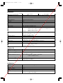
Panasonic WV-CS954E Operating Instructions Manual
- Categoria
- Telecamere di sicurezza
- Tipo
- Operating Instructions Manual
Questo manuale è adatto anche per

Printed in Japan
Gedruckt in Japan
Imprimé au Japon
Impreso en Japón
Stampato in Giappone
© 2004 Matsushita Electric Industrial Co., Ltd. All rights reserved. A0105-3055 3TR003398DAA
Before attempting to connect or operate this product,
please read these instructions carefully and save this manual for future use.
Model Nos. WV-CS950
WV-CS954E
Colour CCTV Camera
Operating Instructions
ENGLISH
DEUTSCH
FRANÇAIS
ESPAÑOL
ITALIANO
www.absolualarme.com met à la disposition du public, via www.docalarme.com, de la documentation technique dont les références, marques et logos, sont la propriété des détenteurs respectifs

-2-
The serial number of this product may be found on the
top of the unit.
You should note the serial number of this unit in the
space provided and retain this book as a permanent
record of your purchase to aid identification in the event
of theft.
Model No. WV-CS950, CS954E
Serial No.
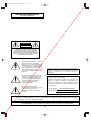
WARNING: To prevent fire or electric shock hazard, do not expose this appliance to rain or moisture.
The apparatus shall not be exposed to dripping or splashing and that no objects filled with liquids, such as
vases, shall be placed on the apparatus.
FOR YOUR SAFETY PLEASE READ THE FOLLOWING TEXT
CAREFULLY.
WARNING
THIS APPARATUS MUST BE EARTHED
IMPORTANT
The wires in this mains lead are coloured in accordance with the fol-
lowing code.
Green-and-yellow: Earth
Blue: Neutral
Brown: Live
As the colours of the wire in the mains lead of this appliance
may not correspond with the coloured markings identifying the ter-
minals in your plug, proceed as follows.
The wire which is coloured green-and-yellow must be connect-
ed to the terminal in the plug which is marked with the letter E or by
the earth symbol 1 or coloured green or green-and-yellow.
The wire which is coloured blue must be connected to the termi-
nal in the plug which is marked with the letter N or coloured black.
The wire which is coloured brown must be connected to the ter-
minal in the plug which is marked with the letter L or coloured red.
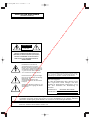
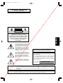
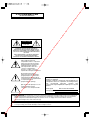
The lightning flash with arrowhead
symbol, within an equilateral triangle,
is intended to alert the user to the
presence of uninsulated "dangerous
voltage" within the product's enclo-
sure that may be of sufficient magni-
tude to constitute a risk of electric
shock to persons.
The exclamation point within an equi-
lateral triangle is intended to alert the
user to the presence of important
operating and maintenance (servic-
ing) instructions in the literature
accompanying the appliance.
Turn the power off at the mains to
disconnect the main power for all
unit.
CAUTION: TO REDUCE THE RISK OF ELECTRIC SHOCK,
DO NOT REMOVE COVER (OR BACK).
NO USER-SERVICEABLE PARTS INSIDE.
REFER SERVICING TO QUALIFIED SERVICE PERSONNEL.
CAUTION
RISK OF ELECTRIC SHOCK
DO NOT OPEN
CAUTION: An ALL-POLE MAINS SWITCH with a contact separation of at least 3 mm in each pole shall be incorporated
in the electrical installation of the building.
Wij verklaren als enige aansprakelijke, dat het product waarop
deze verklaring betrekking heeft, voldoet aan de volgende nor-
men of andere normatieve documenten, overeenkomstig de
bepalingen van Richtlijnen 73/23/EEC en 89/336/EEC.
Vi erklærer os eneansvarlige for, at dette produkt, som denne
deklaration omhandler, er i overensstemmelse med standarder
eller andre normative dokumenter i følge bestemmelserne i
direktivene 73/23/EEC og 89/336/EEC.
Vi deklarerar härmed värt fulla ansvar för att den produkt till
vilken denna deklaration hänvisar är i överensstämmelse med
standarddokument, eller andra normativa dokument som
framställs i EEC-direktiv nr. 73/23 och 89/336.
Ilmoitamme yksinomaisella vastuullamme, että tuote, jota tämä
ilmoitus koskee, noudattaa seuraavia standardeja tai muita
ohjeellisia asiakirjoja, jotka noudattavat direktiivien 73/23/EEC
ja 89/336/EE. säädöksiä.
Vi erklærer oss alene ansvarlige for at produktet som denne
erklæringen gjelder for, er i overensstemmelse med følgende
normer eller andre normgivende dokumenter som følger
bestemmelsene i direktivene 73/23/EEC og 89/336/EEC.
We declare under our sole responsibility that the product to
which this declaration relates is in conformity with the stan-
dards or other normative documents following the provisions of
Directives EEC/73/23 and EEC/89/336.
www.absolualarme.com met à la disposition du public, via www.docalarme.com, de la documentation technique dont les références, marques et logos, sont la propriété des détenteurs respectifs

-3-
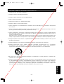
IMPORTANT SAFETY INSTRUCTIONS
1) Read these instructions.
2) Keep these instructions.
3) Heed all warnings.
4) Follow all instructions.
5) Do not use this apparatus near water.
6) Clean only with dry cloth.
7) Do not block any ventilation openings. Install in accordance with the manufacturer's instructions.
8) Do not use near any heat sources such as radiators, heat registers, stoves, or other apparatus (including
amplifiers) that produce heat.
9) Do not defeat the safety purpose of the polarized or grounding-type plug. A polarized plug has two blades with
one wider than the other. A grounding-type plug has two blades and a third grounding prong. The wide blade or
the third prong are provided for your safety. If the provided plug does not fit into your outlet, consult an
electrician for replacement of the obsolete outlet.
10) Protect the power cord from being walked on or pinched particularly at plugs, convenience receptacles and the
points where they exit from the apparatus.
11) Only use attachments/accessories specified by the manufacturer.
12) Use only with the cart, stand, tripod, bracket, or table specified by the manufacturer, or sold with the apparatus.
When a cart is used, use caution when moving the cart/apparatus combination to avoid injury from tip-overs.
13) Unplug this apparatus during lightning storms or when unused for long periods of time.
14) Refer all servicing to qualified service personnel. Servicing is required when the apparatus has been damaged
in any way, such as power-supply cord or plug is damaged, liquid has been spilled or objects fallen into the
apparatus, the apparatus has been exposed to rain or moisture, does not operate normally, or has been
dropped.
S3125A
ENGLISH
www.absolualarme.com met à la disposition du public, via www.docalarme.com, de la documentation technique dont les références, marques et logos, sont la propriété des détenteurs respectifs

-4-
LIMITATION OF LIABILITY
THIS PUBLICATION IS PROVIDED “AS IS” WITHOUT
WARRANTY OF ANY KIND, EITHER EXPRESS OR
IMPLIED, INCLUDING BUT NOT LIMITED TO, THE
IMPLIED WARRANTIES OF MERCHANTABILITY, FIT-
NESS FOR ANY PARTICULAR PURPOSE, OR NON-
INFRINGEMENT OF THE THIRD PARTY'S RIGHT.
IN NO EVENT SHALL MATSUSHITA ELECTRIC
INDUSTRIAL CO., LTD. BE LIABLE TO ANY PARTY OR
ANY PERSON, EXCEPT FOR REPLACEMENT OR
REASONABLE MAINTENANCE OF THE PRODUCT,
FOR THE CASES, INCLUDING BUT NOT LIMITED TO
BELOW:
(1) ANY DAMAGE AND LOSS, INCLUDING WITH-
OUT LIMITATION, DIRECT OR INDIRECT, SPE-
CIAL, CONSEQUENTIAL OR EXEMPLARY,
ARISING OUT OF OR RELATING TO THE
PRODUCT;
(2) PERSONAL INJURY OR ANY DAMAGE
CAUSED BY INAPPROPRIATE USE OR NEGLI-
GENT OPERATION OF THE USER;
(3) UNAUTHORIZED DISASSEMBLE, REPAIR OR
MODIFICATION OF THE PRODUCT BY THE
USER;
THIS PUBLICATION COULD INCLUDE TECHNICAL
INACCURACIES OR TYPOGRAPHICAL ERRORS.
CHANGES ARE ADDED TO THE INFORMATION
HEREIN, AT ANY TIME, FOR THE IMPROVEMENTS OF
THIS PUBLICATION AND/OR THE CORRESPONDING
PRODUCT(S).
DISCLAIMER OF WARRANTY
(4) INCONVENIENCE OR ANY LOSS ARISING
WHEN IMAGES ARE NOT DISPLAYED, DUE TO
ANY REASON OR CAUSE INCLUDING ANY
FAILURE OR PROBLEM OF THE PRODUCT;
(5) ANY PROBLEM, CONSEQUENTIAL INCONVE-
NIENCE, OR LOSS OR DAMAGE, ARISING OUT
OF THE SYSTEM COMBINED BY THE DEVICES
OF THIRD PARTY.
(6) ANY CLAIM OR ACTION FOR DAMAGES,
BROUGHT BY ANY PERSON OR ORGANIZA-
TION BEING PHOTOGENIC SUBJECT, DUE TO
VIOLATION OF PRIVACY WITH THE RESULT OF
THAT SURVEILLANCE-CAMERA's PICTURE,
INCLUDING SAVED DATA, FOR SOME REA-
SON, BECOMES PUBLIC OR IS USED FOR THE
PURPOSE OTHER THAN SURVEILLANCE.
(7) ANY PROBLEM, CONSEQUENTIAL INCONVE-
NIENCE, ANY LOSS OR DAMAGE, ARISING
OUT OF THE IMPROPER DETECTION OR SLIP-
UP IN DETECTION BY VMD (Video Motion
Detector) FUNCTION OF THE PRODUCT.
www.absolualarme.com met à la disposition du public, via www.docalarme.com, de la documentation technique dont les références, marques et logos, sont la propriété des détenteurs respectifs

-5-
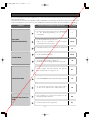
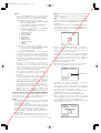
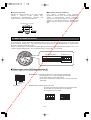
This Colour CCTV Camera is a video surveillance
device that incorporates a 1/4-type {1/4"} CCD, a 30x
zoom lens, preset and pan and tilt capabilities in a
dome configuration. It also has the following features.
■ Super Dynamic
33
(SUPER-D
33
)
SUPER-D 3 makes it possible to capture clear images
of subjects whose illumination is extremely different
(page 22).
■ New DSP for High Sensitivity
A new noise reduction system lowers minimum illumi-
nance to 0.5 lux in the colour mode and 0.04 lux in the
black and white mode.
■ Auto Night time Switching to Black
and White Mode
The camera can be configured to switch to the black
and white mode automatically under low light condi-
tions for clear images, even at night.
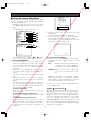
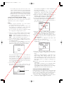
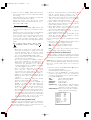
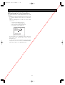
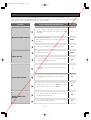
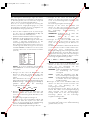
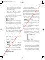
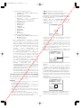
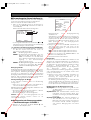
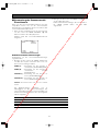
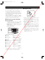
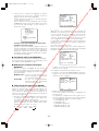
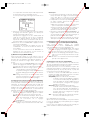
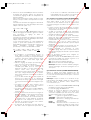
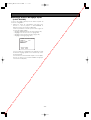
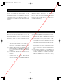
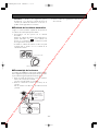
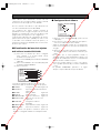
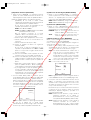
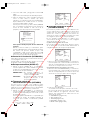
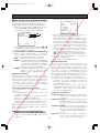
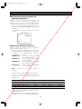
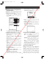
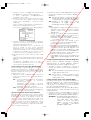
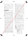
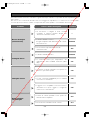
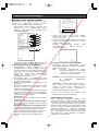
■ Digital Flip
Normally, a camera needs to stop when it points
straight down during a tilt operation. With digital flip,
however, the camera is able to tilt from 0° to 180° in a
single motion. This makes it possible to track subjects
passing directly under the camera more smoothly.
■ Privacy Zone Function
The privacy zone function makes it possible to mask
specific areas of the scene from view.
■ Patrol Function
The patrol function remembers manual camera move-
ment routines for automatic playback when they are
needed. For example, you can teach the camera the
movements of the people you want to monitor, by
replaying the stored parameters complicated move-
ments are done automatically.
■ Camera Position Memory
The system can be configured with up to 256 camera
positions. A particular camera position can be selected
and viewed by entering the applicable preset number
on the system controller 10-key pad.
■ Motion Detection
The system can be configured so any motion on the
monitor screen during surveillance causes output of an
alarm signal.
This function can be used to structure a system with a
VTR that records images of night time intruders.
FEATURES
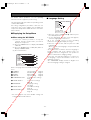
ACCESSORIES
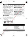
Operating Instructions (this manual) . . . . . . . . . .1 pc. The following items are for installation.
Decorative Cover . . . . . . . . . . . . . . . . . . . . . . . . .1 pc.
Dust Protection Sheet . . . . . . . . . . . . . . . . . . . . . .1 pc.
8P Alarm Cable . . . . . . . . . . . . . . . . . . . . . . . . . . .1 pc.
4P Alarm Cable . . . . . . . . . . . . . . . . . . . . . . . . . . .1 pc.
Connector for 24 V AC (only for WV-CS954E) . . .1 pc.
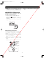
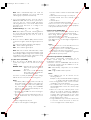
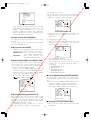
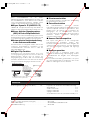
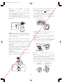
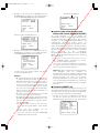
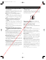
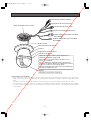
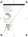
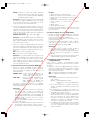
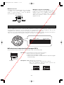
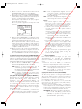
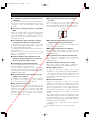
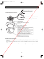
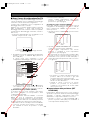
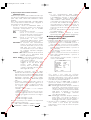
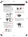
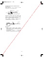
Tilting
downwards
The picture is flipped
when the camera is
pointing straight down
(at around 135°).
Tilting upwards.
· · · Digital flip is performed only when the system controller joystick is held downwards.
Digital Flip Operation
OPTIONAL ACCESSORIES
Dome Cover(approx.50 % transparency,smoked type) . . . . . . .WV-CS3SE
Ceiling Mount Bracket . . . . . . . . . . . . . . . . . . . . . . . . . . . . . . . . .WV-Q105E/WV-Q116E/WV-Q117E
Wall Mount Bracket . . . . . . . . . . . . . . . . . . . . . . . . . . . . . . . . . . .WV-Q118E
www.absolualarme.com met à la disposition du public, via www.docalarme.com, de la documentation technique dont les références, marques et logos, sont la propriété des détenteurs respectifs

PRECAUTIONS
1. Do not attempt to disassemble the camera.
To prevent electric shock, do not remove screws or
covers.
There are no user-serviceable parts inside.
Ask qualified service personnel for servicing.
2. Handle the camera with care.
Do not misuse the camera. Avoid striking, shaking,
etc. The camera could be damaged by improper
handling or storage.
3. Do not expose the camera to rain or moisture,
nor try to operate it in wet areas.
This product is designed for indoor use or locations
where it is protected from rain and moisture.
Turn the power off immediately and ask qualified
service personnel for servicing.
Moisture can damage the camera and also create
the danger of electric shock.
4. Do not use strong or abrasive detergents when
cleaning the camera body.
Use a dry cloth to clean the camera when it is dirty.
When the dirt is hard to remove, use a mild
detergent and wipe gently. Care should be taken
not to scratch the dome cover when wiping it.
Afterwards, wipe off the remaining detergent with a
dry cloth.
5. Never aim the camera at the sun.
Whether or not the camera is in use, never aim it at
the sun or other extremely bright objects.
Otherwise, blooming or smear may be caused.
6. Never aim the camera at strong light sources for
an extended period of time.
A light source such as a spot light causes burn-in
on the display screen. Failure to observe this may
cause the image to become discoloured due to
deterioration of the colour filter in the CCD.
7. Do not install this camera upside down.
This camera is designed for mounting on the ceiling
or wall. Using this camera installed upside down,
for example, mounted on the floor, may cause
malfunction.
8. Do not operate the camera beyond the specified
temperature, humidity or power source ratings.
Do not use the camera in an extreme environment
where high temperature or high humidity exists. Do
not place the camera near heat sources such as
radiators, stoves or other units that produce heat.
Use the camera under conditions where tempera-
ture is between –10 °C - +50 °C, preferably +40 °C
and humidity is below 90 %.
The input power source is 220 V - 240 V AC for WV-
CS950 and 24 V AC for WV-CS954E.
9. Do not install the camera near the air outlet of an
air conditioner.
The lens may become cloudy due to condensation
if the camera is used under the following
conditions.
• Rapid temperature fluctuations by switching the air
conditioner on and off.
• Rapid temperature fluctuations due to frequent door
opening and closing.
• Use in an environment where eyeglasses become
foggy.
• Use in a room filled with cigarette smoke or dust.
If the lens becomes cloudy due to condensation,
remove the dome cover and wipe all moist surfaces
with a soft cloth.
10.Consumables
Parts having contacts such as the lens-drive
motors, cooling fan motor and slip-rings inside the
camera are subject to wear with time. Please ask
the nearest service centre about replacement and
maintenance of such parts.
11.Do not aim the camera at the same object for a
long time.
Burn-in of an image may be caused on the
fluorescent screen of CRT.
12.Self-diagnosis Function
If the camera continues operating abnormally for 30
seconds or more due to such an accident as
external noise, the camera will automatically reset
its power. In the case it happens frequently, check
if there would be any environmental cause.
* Matsushita Electric Industrial Co., Ltd. herewith
declares that it will not be liable for any damage,
whether direct or indirect, caused by using the
product for business transaction or security, or
malfunctioning of this product.
-6-
www.absolualarme.com met à la disposition du public, via www.docalarme.com, de la documentation technique dont les références, marques et logos, sont la propriété des détenteurs respectifs

-7-
OPERATING PRECAUTIONS
■ The camera does not have a power switch
Power turns on as soon as the power cord is plugged
into a power outlet. Before cleaning the camera,
unplug the power cord from the power outlet.
■ What to do if OVER HEAT appears on the display
This message indicates that the interior of the camera
has become very hot. Immediately unplug the power
cord from the power outlet, and contact a qualified
service person or system installer.
■ Note the following to ensure long-term trouble-
free operation
Long operation under high temperatures and high
humidity can cause components to deteriorate and
shorten camera life.
The recommended ambient operation temperature is
less than +35 °C.
Make sure the camera is installed in a location where it
is not directly exposed to heat from a radiator, heater,
etc.
■ Avoid use of this camera in a food preparation
area and other locations where there are large
amounts of steam vapour and oil.
■ About the Camera Cleaning Function
Prolonged use can lead to noise on the monitor and
divergence of preset positions.
If such conditions persist even after you perform
camera cleaning (page 35), use the special setup
menu to execute the “REFRESH” operation (page 39).
■ This camera is designed for use in a hanging
configuration only.
Do not use it in an upright configuration on a tabletop,
floor, etc. Such conditions create the risk of
malfunction.
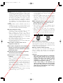
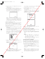
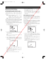
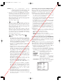
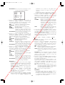
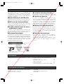
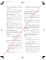
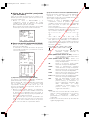
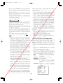
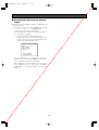
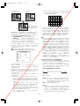
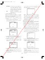
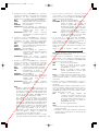
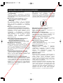
■ CCD colour filter burn-in
Intense light concentrated on one spot for a long
period can cause deterioration of the CCD internal
colour filters, and discoloration of the affected part.
Even if the camera position is changed from a fixed
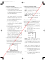
position, the discoloration at the previous location of
the concentrated light will remain on the screen.
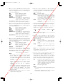
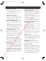
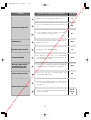
■ Do not point the camera at a strong light source.
Intense light such as that produced by a spotlight
concentrated on one part of the screen can cause
blooming (rainbow around the strong light) or smearing
(vertical stripes above and below the strong light).
■ Do not aim the camera at the same object for a
long time.
Burn-in of an image may be caused on the fluorescent
screen of CRT.
■ Handle the camera carefully.
Do not drop the camera, or subject it to strong impact
or vibration. Such conditions create the risk of
malfunction.
■ Do not allow the camera to become wet.
Make sure that it is not exposed directly to water. Such
conditions create the risk of malfunction.
■ Condensation inside of the dome cover
Remove the dome cover and use a soft cloth to wipe
off the moisture (page 10).
■ Consumables
Parts having contacts such as the lens-drive motors,
cooling fan motor and slip-rings inside the camera are
subject to wear with time. Please ask the nearest
service centre about replacement and maintenance of
such parts.
■ Cleaning the camera
Turn off the camera and wipe it with a soft cloth. If the
camera is very dirty, wipe it off gently with a soft cloth
moistened with a weak solution of water and a neutral
kitchen detergent. Wring all excess liquid from the
cloth before wiping the camera. Next, wipe off all
remaining solution with a soft, dry cloth.
A dirty dome cover or lens causes deterioration of
picture quality. Use lens cleaning paper (like the type
available for cleaning eyeglasses or a camera lens) to
clean the lens.
The dome cover is particularly susceptible to damage.
Gently wipe it with a soft cloth.
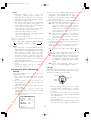
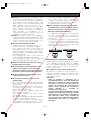
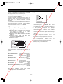
Smearing
Bright Subject
Blooming
www.absolualarme.com met à la disposition du public, via www.docalarme.com, de la documentation technique dont les références, marques et logos, sont la propriété des détenteurs respectifs

-8-
■ Downloading (saving) or uploading (recovering)
camera setting information
Camera setting information that can be downloaded to
the system controller etc, includes existing preset
position settings and menu settings. However, the
following items are not included.
• Patrol function (page 32)
• Area title function (page 34)
• Blemish compensation pattern (page 39)
• RS485 settings (page 20)
• Password settings (page 42)
Be sure the camera is not moving and aimed at
something that moves very little (like a wall) before
downloading camera preset data to the system
controller etc. or uploading downloaded data to the
camera.
Uploading of WV-CS950 series preset data to other
models (e.g. WV-CS850 series, WV-CS850A series,
WV-CS850B series and WV-NS320 series) may cause
an error and failure of the uploading process.
■ Self-diagnosing Function
If abnormal operation due to external noise or some
other reason continues for more than 30 seconds, the
camera will automatically reset itself and restore
normal operation. Reset operation the same
initialisation routine that is performed when the camera
is turned on. If the reset is required too often, it could
mean that the camera is installed in a location where
there is a large amount of external noise. This can
cause malfunction of the camera, so you should
contact a qualified service person or system installer
as soon as possible.
www.absolualarme.com met à la disposition du public, via www.docalarme.com, de la documentation technique dont les références, marques et logos, sont la propriété des détenteurs respectifs

-9-
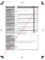
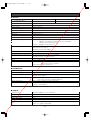
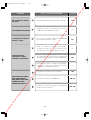
CONTENTS
IMPORTANT SAFETY INSTRUCTIONS . . . . . . . . . . . . . . . . . . . . . . . . . . . . . . . . . . . . . . . . . .3
LIMITATION OF LIABILITY . . . . . . . . . . . . . . . . . . . . . . . . . . . . . . . . . . . . . . . . . . . . . . . . . . . .4
DISCLAIMER OF WARRANTY . . . . . . . . . . . . . . . . . . . . . . . . . . . . . . . . . . . . . . . . . . . . . . . . .4
FEATURES . . . . . . . . . . . . . . . . . . . . . . . . . . . . . . . . . . . . . . . . . . . . . . . . . . . . . . . . . . . . . . . .5
■ Super Dynamic 3 (SUPER-D 3) . . . . . . . . . . . . . . . . . . . . . . . . . . . . . . . . . . . . . . . . . . .5
■ New DSP for High Sensitivity . . . . . . . . . . . . . . . . . . . . . . . . . . . . . . . . . . . . . . . . . . . . . .5
■ Auto Nighttime Switching to Black and White Mode . . . . . . . . . . . . . . . . . . . . . . . . . . . .5
■ Digital Flip . . . . . . . . . . . . . . . . . . . . . . . . . . . . . . . . . . . . . . . . . . . . . . . . . . . . . . . . . . . .5
■ Privacy Zone Function . . . . . . . . . . . . . . . . . . . . . . . . . . . . . . . . . . . . . . . . . . . . . . . . . . .5
■ Patrol Function . . . . . . . . . . . . . . . . . . . . . . . . . . . . . . . . . . . . . . . . . . . . . . . . . . . . . . . . .5
■ Camera Position Memory . . . . . . . . . . . . . . . . . . . . . . . . . . . . . . . . . . . . . . . . . . . . . . . . .5
■ Motion Detection . . . . . . . . . . . . . . . . . . . . . . . . . . . . . . . . . . . . . . . . . . . . . . . . . . . . . . .5
ACCESORIES . . . . . . . . . . . . . . . . . . . . . . . . . . . . . . . . . . . . . . . . . . . . . . . . . . . . . . . . . . . . .5
OPTIONAL ACCESORIES . . . . . . . . . . . . . . . . . . . . . . . . . . . . . . . . . . . . . . . . . . . . . . . . . . . .5
PRECAUTIONS . . . . . . . . . . . . . . . . . . . . . . . . . . . . . . . . . . . . . . . . . . . . . . . . . . . . . . . . . . . .6
OPERATING PRECAUTIONS . . . . . . . . . . . . . . . . . . . . . . . . . . . . . . . . . . . . . . . . . . . . . . . . .7
CONSTRUCTION . . . . . . . . . . . . . . . . . . . . . . . . . . . . . . . . . . . . . . . . . . . . . . . . . . . . . . . . . .10
INSTALLATION PRECAUTIONS . . . . . . . . . . . . . . . . . . . . . . . . . . . . . . . . . . . . . . . . . . . . . .11
DIP SWITCH SETTINGS . . . . . . . . . . . . . . . . . . . . . . . . . . . . . . . . . . . . . . . . . . . . . . . . . . . .12
■ Communication Parameters (DIP Switch 2) . . . . . . . . . . . . . . . . . . . . . . . . . . . . . . . . . .12
■ Unit Number (DIP Switch 1) . . . . . . . . . . . . . . . . . . . . . . . . . . . . . . . . . . . . . . . . . . . . . .13
■ RS485 Communication Parameters (DIP Switch 1) . . . . . . . . . . . . . . . . . . . . . . . . . . . .14
CAMERA INSTALLATION . . . . . . . . . . . . . . . . . . . . . . . . . . . . . . . . . . . . . . . . . . . . . . . . . . .15
■ Preparing the Camera and Decorative Cover for Side Cable Exit . . . . . . . . . . . . . . . . .15
■ Installing the Camera . . . . . . . . . . . . . . . . . . . . . . . . . . . . . . . . . . . . . . . . . . . . . . . . . . .15
UNINSTALLING THE CAMERA . . . . . . . . . . . . . . . . . . . . . . . . . . . . . . . . . . . . . . . . . . . . . .17
■ Removing the Decorative Cover . . . . . . . . . . . . . . . . . . . . . . . . . . . . . . . . . . . . . . . . . . .17
■ Uninstalling the Camera . . . . . . . . . . . . . . . . . . . . . . . . . . . . . . . . . . . . . . . . . . . . . . . . .17
CONNECTIONS . . . . . . . . . . . . . . . . . . . . . . . . . . . . . . . . . . . . . . . . . . . . . . . . . . . . . . . . . . .18
RS485 SETUP . . . . . . . . . . . . . . . . . . . . . . . . . . . . . . . . . . . . . . . . . . . . . . . . . . . . . . . . . . . .20
USING THE SETUP MENU . . . . . . . . . . . . . . . . . . . . . . . . . . . . . . . . . . . . . . . . . . . . . . . . . .21
■ Displaying the Setup Menu . . . . . . . . . . . . . . . . . . . . . . . . . . . . . . . . . . . . . . . . . . . . . .21
■ Language Setting . . . . . . . . . . . . . . . . . . . . . . . . . . . . . . . . . . . . . . . . . . . . . . . . . . . . . .21
CAMERA SETTINGS . . . . . . . . . . . . . . . . . . . . . . . . . . . . . . . . . . . . . . . . . . . . . . . . . . . . . . .22
■ Using the Camera Setup Menu . . . . . . . . . . . . . . . . . . . . . . . . . . . . . . . . . . . . . . . . . . .22
PAN/TILT SETTINGS . . . . . . . . . . . . . . . . . . . . . . . . . . . . . . . . . . . . . . . . . . . . . . . . . . . . . . .27
■ Using the Pan/Tilt Setup Menu . . . . . . . . . . . . . . . . . . . . . . . . . . . . . . . . . . . . . . . . . . . .27
ALARM SETTINGS . . . . . . . . . . . . . . . . . . . . . . . . . . . . . . . . . . . . . . . . . . . . . . . . . . . . . . . . .36
■ Using the Alarm Setup Menu . . . . . . . . . . . . . . . . . . . . . . . . . . . . . . . . . . . . . . . . . . . . .36
SPECIAL SETTINGS . . . . . . . . . . . . . . . . . . . . . . . . . . . . . . . . . . . . . . . . . . . . . . . . . . . . . . .39
■ Using the Special Setup Menu . . . . . . . . . . . . . . . . . . . . . . . . . . . . . . . . . . . . . . . . . . . .39
SCENE SELECT SETTING . . . . . . . . . . . . . . . . . . . . . . . . . . . . . . . . . . . . . . . . . . . . . . . . . . .40
■ Using the Scene Select Setting Menu . . . . . . . . . . . . . . . . . . . . . . . . . . . . . . . . . . . . . .40
QUICK MENU SETTINGS . . . . . . . . . . . . . . . . . . . . . . . . . . . . . . . . . . . . . . . . . . . . . . . . . . .41
■ Displaying the Quick Setup Menu . . . . . . . . . . . . . . . . . . . . . . . . . . . . . . . . . . . . . . . . .41
PASSWORD SETTINGS . . . . . . . . . . . . . . . . . . . . . . . . . . . . . . . . . . . . . . . . . . . . . . . . . . . . .42
■ Password Lock Settings . . . . . . . . . . . . . . . . . . . . . . . . . . . . . . . . . . . . . . . . . . . . . . . . .42
SHORTCUTS . . . . . . . . . . . . . . . . . . . . . . . . . . . . . . . . . . . . . . . . . . . . . . . . . . . . . . . . . . . . .44
TROUBLESHOOTING . . . . . . . . . . . . . . . . . . . . . . . . . . . . . . . . . . . . . . . . . . . . . . . . . . . . . .46
SPECIFICATIONS . . . . . . . . . . . . . . . . . . . . . . . . . . . . . . . . . . . . . . . . . . . . . . . . . . . . . . . . .50
www.absolualarme.com met à la disposition du public, via www.docalarme.com, de la documentation technique dont les références, marques et logos, sont la propriété des détenteurs respectifs

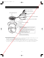
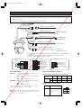
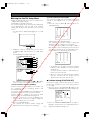
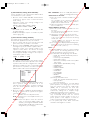
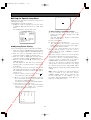
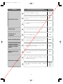
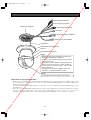
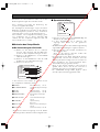
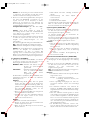
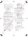
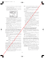
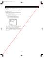
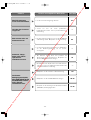
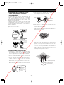
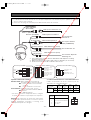
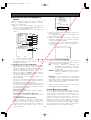
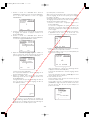
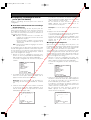
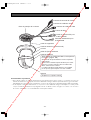
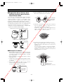
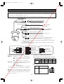
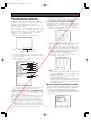
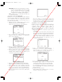
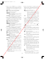
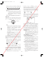
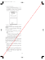
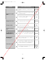
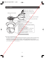
CONSTRUCTION
Ensuring Trouble-free Operation
• This camera uses a “slip ring” for transmission of electrical power and signals. A dirty slip ring can cause
deterioration of picture quality during panning and generation of noise.
In order to ensure trouble-free camera operation, make sure that the cleaning function (page 35) is turned on.
• If cleaning the slip ring does not eliminate poor picture quality and noise, it could mean that the slip ring has
reached the end of its service life. Contact a qualified service person or system installer to have it replaced.
-10-
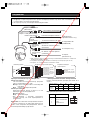
Power Connector for WV-CS954E
Power Connector for WV-CS950
Video Output Connector
Decorative Cover (provided)
Dome Fix Ring
Safety Wire
Lens
The lens cannot be replaced.
Data Port
Alarm Output Connector
Alarm Input Connector
Camera Mounting Base
Dome Cover
Remove the camera first before removing the
dome cover (page 17).
Rotate the dome fix ring to the left to remove it.
Tighten the dome fix ring securely to prevent it from
coming loose. Securely anchor the camera when
removing the dome cover.
The dome cover is easily damaged,
and should be handled with care.
Camera
www.absolualarme.com met à la disposition du public, via www.docalarme.com, de la documentation technique dont les références, marques et logos, sont la propriété des détenteurs respectifs

INSTALLATION PRECAUTIONS
Warning: Discuss the installation location for the
camera with your retailer, and select a place that is
strong enough for the installation. If you install the
camera on a ceiling or wall, except for accidents
caused by fault in the camera, Panasonic holds
absolutely no responsibility for accidents caused by
the camera falling due to unsuitable installation.
Take sufficient care when installing the camera. If
the installation is not strong enough, be sure to
sufficiently reinforce the location and check that it is
safe.
Warning: Always request installation work from a
qualified service person or system installer. Lack of
technical knowledge creates the risk of fire, electric
shock, personal injury, and material damage.
■ Camera Installation Location
• Install the camera on a ceiling (concrete, etc.) at a
location that is sufficiently strong to support it.
• When installing the camera on a ceiling of
insufficient strength (like a drop ceiling), use the
optionally available WV-Q105E Direct Attachment
Ceiling Mounting Bracket or the WV-Q116E
Embedded Ceiling Mount Bracket.
• For ceiling mounting, use the optionally available
WV-Q117E Ceiling Mount Bracket.
• For wall mounting, use the optionally available WV-
Q118E Wall Mount Bracket.
■ This camera is an indoor camera. It is not
designed for outdoor use.
■ This camera is designed for use in a hanging con-
figuration only. Using it in an upright or inclined
configuration can cause malfunction and shorten
the life of the camera.
■ Install the camera in a horizontal configuration,
with the dome pointed downwards.
■ Never install or use the camera in the following
locations.
• Areas directly exposed to rain and water
• Near a swimming pool or other areas where
chemicals are used
• Food preparation areas and other locations where
there are large amounts of steam vapour and oil, in
flammable atmospheres, other special environments
• Areas where radiation, X-rays, strong electric
waves, or magnetism is generated
• At sea, in coastal areas, or in areas where corrosive
gas is being generated
• Areas outside of the allowable ambient operating
temperature range (-10 °C to +50 °C)
• In a motor vehicle, on a boat, or other areas subject
to strong vibration (This camera is not designed for
use in a vehicle.)
• Near an air conditioner outlet, near a door that opens
up to the outdoors, or any other area subjected to
temperature extremes (Such conditions can cause
clouding and condensation formation on the dome
cover.)
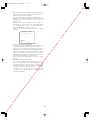
■ When wiring the camera, its cables (power, video
output, RS485, alarm in, alarm out) can exit out
the side or the top of the camera.
• When using the top cable exit configuration, drill a
hole in the ceiling to allow passage of the cables.
(See step 3 on page 15.)
• When using the side cable exit configuration,
prepare the cut-out in the die cast case and
decorative cover. (See “Preparing the Camera and
Decorative Cover for Side Cable Exit” on page 15.)
■ Noise interference considerations
When using a power line that is greater than 240 V AC
and wiring that is longer than 1 meter, wiring should be
performed using a separate metal conduit. (The metal
conduit must be earth grounded.)
■ Screws should be ordered separately.
The camera does not come with screws. Make sure
that the materials and structure of the installation
location is strong enough to support the total weight of
the camera.
Important:
• Before setting up the camera for a configuration
where the camera's RS485 data port is used for
camera control (pan, tilt, etc.) by the system
controller, the camera's DIP switches must be
configured to specify the unit number and
communication parameters. (page 12)
If DIP switch setting is not performed, the
system controller control will not be possible
and camera setup will have to be performed
again. Be sure to check the DIP switch settings
before setting up the camera.
-11-
www.absolualarme.com met à la disposition du public, via www.docalarme.com, de la documentation technique dont les références, marques et logos, sont la propriété des détenteurs respectifs

-12-
Notes:
• If you need to connect a ground, be sure to do it
before you connect the main power plug. Also,
when removing the ground, be sure to disconnect
the main power plug.
• The camera does not have a power switch, so it
turns on as soon as the power cord is plugged into
a power outlet. A self-cleaning function is activated
(PAN/TILT/ZOOM/FOCUS) when the camera is
turned on.
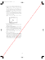
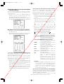
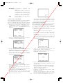
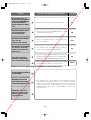
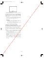
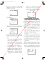
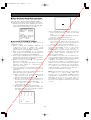
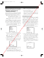
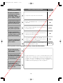
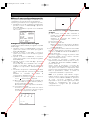
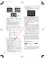
■ Heat radiation
The surface of the camera radiates heat. Ventilation
holes should be provided when installing the camera in
an enclosed ceiling or confined location where heat
can build up.
■ Beware of high humidity.
If the camera is installed when humidity is very high,
moisture may collect in the camera and cause the
dome to become foggy. If the dome becomes foggy,
remove it when the humidity is low and eliminate the
moisture inside the camera, and then replace the
dome. (page 7, 10)
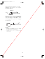
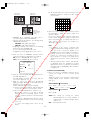
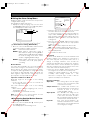
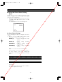
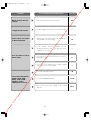
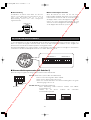
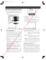
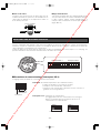
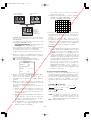
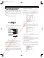
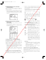
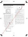
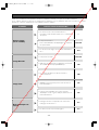
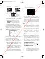
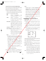
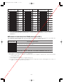
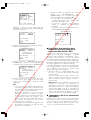
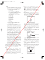
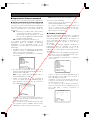
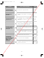
DIP SWITCH SETTINGS
In a configuration where the camera's RS485 data port is used for camera control (pan, tilt, etc.) by the system
controller, the camera's DIP switches must be configured to specify the unit number and communication parameters.
The camera mounting base needs to be removed to access the DIP switches. See steps 1 and 2 on page 15 for
information about how to remove the camera mounting base.
1234
ON
1234
ON
5678
DIP Switch 1 DIP Switch 2
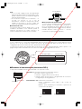
■ Communication Parameters (DIP Switch 2)
The factory default settings of these DIP switches are all OFF.
Switch 1: Terminator (Internal Termination Resistance)
Set it to ON in the following situations.
• When only one camera is connected.
• When only one camera is connected via a daisy chain over a long
distance.
Switches 2 through 4: Communication Parameters
This setting toggles between 2-line and 4-line communication.
Use these switches to select the communication protocol
being used.
1234
ON
Terminator
Communication
Parameters
1234
ON
4-line Communication
1234
ON
2-line Communication
Ventilation holes
www.absolualarme.com met à la disposition du public, via www.docalarme.com, de la documentation technique dont les références, marques et logos, sont la propriété des détenteurs respectifs

-13-
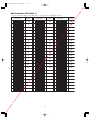
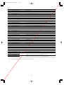
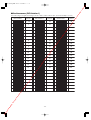
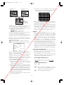
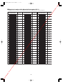
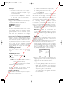
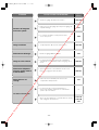
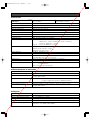
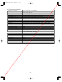
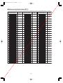
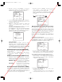
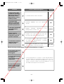
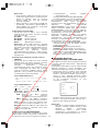
■ Unit Number (DIP Switch 1)
The factory default settings of these DIP switches are all OFF. (Coaxial Multiplex System)
1234
ON
5678
DIP Switch 1
Unit
Number
1234
ON
5678
1234
ON
5678
1234
ON
5678
1234
ON
5678
1234
ON
5678
1234
ON
5678
1234
ON
5678
1234
ON
5678
1234
ON
5678
1234
ON
5678
1234
ON
5678
1234
ON
5678
1234
ON
5678
1234
ON
5678
1234
ON
5678
1234
ON
5678
1234
ON
5678
1234
ON
5678
1234
ON
5678
1234
ON
5678
1234
ON
5678
1234
ON
5678
1234
ON
5678
1234
ON
5678
1234
ON
5678
1234
ON
5678
1234
ON
5678
1234
ON
5678
1234
ON
5678
1234
ON
5678
1234
ON
5678
DIP Switch 1
Unit
Number
DIP Switch 1
Unit
Number
1 ~ 96 *
1
2
3
4
5
6
7
8
9
10
11
12
13
14
15
16
17
18
19
20
21
22
23
24
25
26
27
28
29
30
31
32
33
34
35
36
37
38
39
40
41
42
43
44
45
46
47
48
49
50
51
52
53
54
55
56
57
58
59
60
61
62
63
64
65
66
67
68
1234
ON
5678
1234
ON
5678
1234
ON
5678
1234
ON
5678
1234
ON
5678
1234
ON
5678
1234
ON
5678
1234
ON
5678
1234
ON
5678
1234
ON
5678
1234
ON
5678
1234
ON
5678
1234
ON
5678
1234
ON
5678
1234
ON
5678
1234
ON
56 8
1234
ON
5678
1234
ON
5678
1234
ON
5678
1234
ON
56 8
1234
ON
5678
1234
ON
5678
1234
ON
5678
1234
ON
5678
1234
ON
5678
1234
ON
5678
1234
ON
5678
1234
ON
5678
1234
ON
5678
1234
ON
5678
1234
ON
5678
1234
ON
5678
1234
ON
5678
1234
ON
5678
1234
ON
5678
1234
ON
5678
1234
ON
5678
7
7
www.absolualarme.com met à la disposition du public, via www.docalarme.com, de la documentation technique dont les références, marques et logos, sont la propriété des détenteurs respectifs

-14-
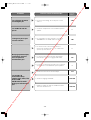
* When using the Unit Number 1 to 96 setting, the unit number setting needs to be configured using the RS485 SET UP menu. For details
about configuring this setting, see step 2 and page 20.
* Turning on power when this setting is selected causes the RS485 SET UP menu to appear during the initialisation routine.
1234
ON
5678
DIP Switch 1
Unit
Number
1234
ON
5678
1234
ON
5678
1234
ON
5678
1234
ON
5678
1234
ON
5678
1234
ON
5678
1234
ON
5678
1234
ON
5678
1234
ON
5678
1234
ON
5678
1234
ON
5678
1234
ON
5678
1234
ON
5678
1234
ON
5678
1234
ON
5678
1234
ON
5678
1234
ON
5678
DIP Switch 1
Unit
Number
DIP Switch 1
Unit
Number
69
70
71
72
73
74
75
76
77
78
79
80
81
82
83
84
85
86
87
88
89
90
91
92
93
94
95
1234
ON
5678
1234
ON
5678
1234
ON
5678
1234
ON
5678
1234
ON
5678
1234
ON
5678
1234
ON
5678
1234
ON
5678
1234
ON
567
8
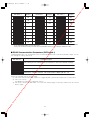
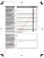
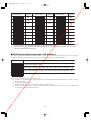
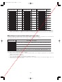
■ RS485 Communication Parameters (DIP Switch 1)
Configuring DIP Switch 1 as shown below resets communication parameters to their factory default settings. You can
then change the settings as desired.
1234
ON
5678
DIP Switch 1 Setting Description
1234
ON
5678
1234
ON
5678
1234
ON
5678
This setting resets communication parameters to the factory default settings.
BAUD RATE : 19 200 bit/s, DATA BIT : 8 bit, PARITY CHECK : NONE, STOP BIT : 1 bit
BAUD RATE : 9 600 bit/s, DATA BIT : 8 bit, PARITY CHECK : NONE, STOP BIT : 1 bit
BAUD RATE : 4 800 bit/s, DATA BIT : 8 bit, PARITY CHECK : NONE, STOP BIT : 1 bit
ON
Perform the following steps to use this setting.
(1) Turn off the camera and use DIP Switch 1 to configure RS485 communication parameters as shown above.
(2) Turn on the camera.
This applies the setting you configured in step (1).
(3) Turn off the camera, use DIP Switch 1 to set the unit number (pages 13 and 14), and then turn the camera
back on again.
www.absolualarme.com met à la disposition du public, via www.docalarme.com, de la documentation technique dont les références, marques et logos, sont la propriété des détenteurs respectifs

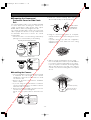
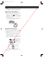
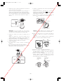
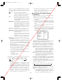
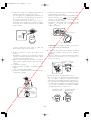
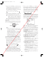
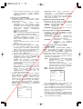
CAMERA INSTALLATION
■ Preparing the Camera and
Decorative Cover for Side Cable
Exit
The camera and decorative cover should be prepared
as shown below when mounting the camera on a
ceiling or wall with its cables (power, video output,
RS485, alarm in, alarm out) exiting from the side.
The camera mounting base needs to be removed in
order to prepare the camera. See steps 1 and 2 below
for information about how to remove the camera
mounting base.
* Prevent the dome cover from being scratched by
placing it on a soft cloth while you are working.
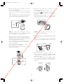
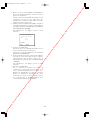
■ Installing the Camera
• Select an installation location that is strong enough
to withstand the total weight of the camera.
Installing the camera at a location that is too weak
can cause it to fall.
• Remove the protective sheet after the installation
work is complete.
• If you are using an optional bracket to install the
camera, install the bracket in accordance with the
instructions that come with it.
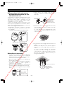
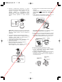
1. Remove the fixing screw (M3 × 6) that secures the
camera to the camera mounting base.
Put the screw in a place where it will not become
lost.
2. Rotate the camera mounting base unit in the
direction indicated by the arrow and remove it.
3. Using the camera mounting base as a template,
mark the locations of the four mounting holes on the
ceiling.
If you are using the top cable exit configuration,
mark the location of the cable hole on the ceiling
and drill the hole.
4. Affix the camera mounting base onto the ceiling.
Use screws (M4) at the locations you marked above
to secure the camera mounting base to the ceiling.
If you do not plan to install the camera right away,
affix the dust protection sheet that comes with the
camera to the camera mounting base to keep dust
off of it.
-15-
Break it off
with a pair of
pliers.
Cut it off
with a
razor knife.
Preparing the Camera Die Cast Case*
Preparing the Decorative Cover
After loosening
the screw, press
upwards on the
camera and then
remove it.
Fixing screw
Rotate
Pull the camera
mounting base
up to remove it.
15°
Mark here
Screws
(M4, available separately)
Dust Protection Sheet
(comes with camera)
www.absolualarme.com met à la disposition du public, via www.docalarme.com, de la documentation technique dont les références, marques et logos, sont la propriété des détenteurs respectifs

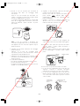
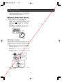
5. Attach the safety wire for securing the camera to
the camera mounting base.
Pull on the safety wire to make sure its ring is
securely connected to the camera mounting base
hook.
If the dust protection sheet that comes with the
camera is affixed to the camera mounting base,
remove it before performing the above step.
Note: The safety wire is designed to allow the
camera to hang from it. Do not apply force greater
than the weight of the camera to the wire.
6. Install the camera onto the camera mounting base.
Aligning with the camera mounting base, press
down on the camera as far as it will go and rotate in
the direction indicated by the arrow.
7. Use the fixing screw you removed in step 1 to
secure the camera to the camera mounting base.
8. Check the installation.
• Is the camera is level and installed securely?
• Is the camera free of looseness?
• Does the fixed part of the camera remain in place
when you try to rotate it?
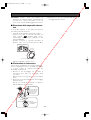
9. Separate the two parts of the decorative cover
(comes with camera).
Press upwards on the decorative cover at the
points marked (indicated by the arrows, in the
illustration below) to unhook the two parts from
each other.
* When removing the decorative cover, the direction
to press ( ) is shown on the side of the decorative
cover.
Caution: Pressing up on the wrong side of the
decorative cover can damage it.
10.Put the two pieces of the decorative cover on the
left and right side of the camera, and hook them
together.
Align the hooks and press the piece indicated by
the arrow in the illustration below into the other
piece.
11.Slide the decorative cover up to the ceiling.
• In the case of a top cable exit configuration, slide
the decorative cover straight up and press it firmly
against the ceiling.
• In the case of a side cable exit configuration, align
the cut-out in the decorative cover with the cables
as you slide it up, and press it firmly against the
ceiling.
➡
-16-
Safety
wire ring
Camera
Camera
Mounting
Base
Rotate
15°
Unhook
Back
Fix securely
Press
Fix securely
Press
Press
Hold
securely
Back
Hold
securely
Align
hook
Press
Top Cable Exit
Configuration
Side Cable Exit
Configuration
Align with
cut-out
www.absolualarme.com met à la disposition du public, via www.docalarme.com, de la documentation technique dont les références, marques et logos, sont la propriété des détenteurs respectifs

UNINSTALLING THE CAMERA
Caution: Make sure you perform the steps below
carefully and exactly when uninstalling the camera
and decorative cover. Failure to do so creates the
risk of damage to the camera.
■ Removing the Decorative Cover
Note that you need to separate the two parts of the
decorative cover in order to remove it.
1. Unhook the two parts of the decorative cover.
Press upwards on the decorative cover at the
points marked (indicated by the arrows, in the
illustration below) to unhook the two parts from
each other.
* When removing the decorative cover, the direction
to press ( ) is shown on the side of the decorative
cover.
■ Uninstalling the Camera
The camera and its base unit are secured by screws.
This configuration provides double anchoring, and you
should use the following procedure to uninstall the
camera.
1. Remove the fixing screw that secures the camera to
the camera mounting base.
Put the screw in a place where it will not become
lost.
2. Remove the camera from the camera mounting
base.
Rotate the camera in the direction indicated by the
arrow and remove it.
➡
-17-
Unhook
Back
Fix securely
Press
Fix securely
Press
3. Remove the safety wire from the camera mounting
base.
Camera
Camera
Mounting
Base
Fixing screw
Rotate
15°
After loosening
the screw, press
upwards on the
camera and then
remove it.
www.absolualarme.com met à la disposition du public, via www.docalarme.com, de la documentation technique dont les références, marques et logos, sont la propriété des détenteurs respectifs

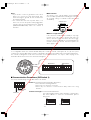
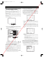
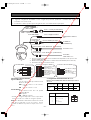
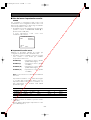
Pin no. Power source
1
2
3
4
24 V AC LIVE
24 V AC NEUTRAL
Ground
Not use
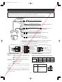
CONNECTIONS
-18-
RS485 Data Port
Alarm Input Connector
Alarm Output Connector
T(B)
T(A)
R(B)
R(A)
Red
Orange
Yellow
Green
Data
Tx
Data
Rx
(RJ-12)
Alarm In 2 (Red)
Alarm In 1 (Black)
GND (Brown)
Alarm In 3 (Yellow)
Alarm In 4 (Blue)
GND (Orange)
GND (
Light Blue or Green
)
GND (Violet)
Alarm Out 2 (Pink)
Alarm Out 1 (Grey)
GND (White)
GND (Light Green
or Light Blue)
Coaxial Cable (5C-2V)*2
220 V - 240 V AC
(WV-CS950)
24 V AC Cable for camera
RS485 Data Port
To VIDEO IN port
(CAMERA IN)
8P Alarm Cable (provided)
PP Alarm Cable (provided)
To sensor, etc.
To buzzer,
display device, etc.
To Matrix Switcher,
etc.
Video Output
Connector
Alarm Input
Connector
Alarm Output
Connector
Twisted Pair Cable*1
(BNC)
(RJ-12)
24 V AC (WV-CS954E)
*1: For twisted pair cable, use shielded low-impedance cable with a thickness of at least AWG#22
(0.33 mm
2
).
*2: Keep the overall length of coaxial cable under 1200 meters (in the case of 5C-2V).
*3: Be sure to connect the grounding cable to ground.
Alarm In/Out Ratings
Alarm In : 5 V DC pull-up input. Drive capacity of at
lease 0.2 mA required.
OFF : 4 V DC minimum 5 V DC maximum,
or open
ON : 1 V DC maximum or short
Alarm Out : Open collector output. 16 V DC, 100 mA
maximum drive capacity
OFF : Open
ON : 100 mA maximum
* When connecting to an external device, set up the
system so the ratings are not exceeded.
Note: Do not turn off camera power within 30 seconds
after turning it on. Doing so can cause pan, tilt, zoom,
or focus to go out of position.
Precautions
• The following connections should be made by qualified service personnel or system installers in accordance
with all local codes.
• See the reverse side of the cover page for main lead connection.
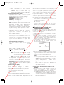
#24
(0.22mm
2
)
Copper wire size
(AWG)
Length
of cable
(approx.)
(m)
(ft)
#22
(0.33mm
2
)
#20
(0.52mm
2
)
#18
(0.83mm
2
)
20 30 45 75
65 100 160 260
• 24 V AC Power Supply Connection
Recommended wire gauge sizes for 24 V AC line
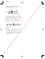
Accessory Connector Information
1
3
2
4
www.absolualarme.com met à la disposition du public, via www.docalarme.com, de la documentation technique dont les références, marques et logos, sont la propriété des détenteurs respectifs

-19-
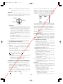
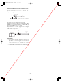
Contact
Insert
Up
A
Approx.
3 mm (0.1 inch)
Insert the wire until A position
and clamp the contacts.
Wire
Up
Contact
Wire
Approx. 3 mm
Insert the wire until A position
and clamp the contacts.
Contact
Up
Wire
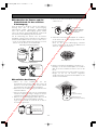
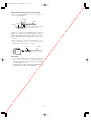
How to Assemble the Cable with the Accessory
Connector
Strip back the cable jacket approx. 3 mm and separate
the individual conductors.
Prepare the individual conductors for clamping. Use
MOLEX band tool part number 57027-5000 (for UL-
Style Cable UL1015) or 57026-5000 (for UL-Style
UL1007) for clamping the contacts.
After clamping the contacts, push them into the proper
holes in the accessory connector of this camera until
they snap in place.
Cautions:
• Shrinking the cable-entry seal is a one-time
procedure. Do not shrink the cable-entry seal until
ascertaining that the unit is functioning.
• CONNECT THIS TO 24 V AC CLASS 2 POWER
SUPPLY ONLY.
www.absolualarme.com met à la disposition du public, via www.docalarme.com, de la documentation technique dont les références, marques et logos, sont la propriété des détenteurs respectifs

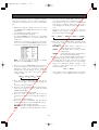
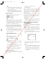
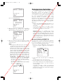
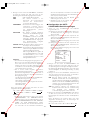
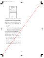
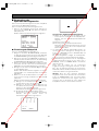
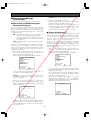
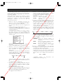
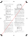
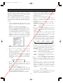
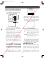
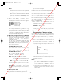
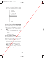
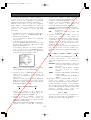
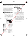
RS485 SETUP
Use the following procedure to configure the RS485
setup when you want to use the system controller to
control the camera (pan, tilt, etc.) via the camera's data
port.
1. Display the setup menu (page 21), move the cursor
to COMMUNICATION O, and then press the CAM
(SET) button.
This will display the RS485 setup menu.
2. Check the unit number. (page 13)
The UNIT NUMBER item shows the unit number
specified by DIP Switch 1. The factory default unit
number is 1.
If DIP Switch 1 specifies 1 to 96 as the unit number,
move the cursor to UNIT NUMBER and then tilt the
joystick left or right to select a unit number (1 to 96).
Note: It is not necessary to configure the RS485
SET UP menu SUB ADDRESS setting.
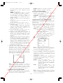
3. Move the cursor to BAUD RATE, and then tilt the
joystick left or right to select a baud rate setting.
Tilting the joystick cycles through the baud rate
(transmission speed) display in the sequence
shown below. (unit: bits/s) The factory default
setting is 19200.
4. Move the cursor to DATA BIT, and then tilt the
joystick left or right to select a data bit setting (7 or
8).
The factory default setting is 8.
5. Move the cursor to PARITY CHECK, and then tilt the
joystick left or right to select a parity bit setting
(NONE, ODD, EVEN).
The factory default setting is NONE.
6. Move the cursor to STOP BIT, and then tilt the
joystick left or right to select a stop bit setting (1 or
2).
The factory default setting is 1.
7. Move the cursor to XON/XOFF, and then tilt the
joystick left or right to select an XON/XOFF setting.
The factory default setting is NOT USE.
NOT USE: Disables X ON/X OFF data flow control.
USE : Enables X ON/X OFF data flow control.
8. Move the cursor to WAIT TIME, and then tilt the
joystick left or right to select a wait time setting.
The wait time is the time that the camera should
wait before resending data when no receive
acknowledgement (ACK) is returned after data is
sent.
Tilting the joystick cycles through the wait time
display in the sequence shown below. (unit: ms)
The factory default setting is OFF.
9. Move the cursor to ALARM DATA, and then tilt the
joystick left or right to select an alarm data send
mode setting.
POLLING : Sends alarm data in response to a
request by the system controller.
AUTO1 : Sends alarm data each time an alarm
signal is input.
AUTO2 : Sends alarm data at five-second intervals.
This is the factory default setting.
10.Move the cursor to DELAY TIME, and then tilt the
joystick left or right to select a delay time setting.
The delay time is the time is the time the camera
should wait before sending a receive acknowledge
(ACK). The delay time display changes in the
sequence shown below. (unit: ms) The factory
default setting is OFF.
This setting can be configured only when 2-line
configuration is selected by DIP Switch 2. (page 12)
-20-
** RS485 SETUP **
UNIT NUMBER
SUB ADDRESS
BAUD RATE
DATA BIT
PARITY CHECK
STOP BIT
XON/XOFF
WAIT TIME
ALARM DATA
DELAY TIME
RET TOP
1
-----
19200
8
NONE
1
NOT USE
OFF
AUTO2
OFF
2400 4800 9600 19200
OFF ↔ 100MS ↔ 200MS ↔ 400MS ↔ 1000MS
OFF ↔ 100MS
www.absolualarme.com met à la disposition du public, via www.docalarme.com, de la documentation technique dont les références, marques et logos, sont la propriété des détenteurs respectifs
La pagina si sta caricando...
La pagina si sta caricando...
La pagina si sta caricando...
La pagina si sta caricando...
La pagina si sta caricando...
La pagina si sta caricando...
La pagina si sta caricando...
La pagina si sta caricando...
La pagina si sta caricando...
La pagina si sta caricando...
La pagina si sta caricando...
La pagina si sta caricando...
La pagina si sta caricando...
La pagina si sta caricando...
La pagina si sta caricando...
La pagina si sta caricando...
La pagina si sta caricando...
La pagina si sta caricando...
La pagina si sta caricando...
La pagina si sta caricando...
La pagina si sta caricando...
La pagina si sta caricando...
La pagina si sta caricando...
La pagina si sta caricando...
La pagina si sta caricando...
La pagina si sta caricando...
La pagina si sta caricando...
La pagina si sta caricando...
La pagina si sta caricando...
La pagina si sta caricando...
La pagina si sta caricando...
La pagina si sta caricando...
La pagina si sta caricando...
La pagina si sta caricando...
La pagina si sta caricando...
La pagina si sta caricando...
La pagina si sta caricando...
La pagina si sta caricando...
La pagina si sta caricando...
La pagina si sta caricando...
La pagina si sta caricando...
La pagina si sta caricando...
La pagina si sta caricando...
La pagina si sta caricando...
La pagina si sta caricando...
La pagina si sta caricando...
La pagina si sta caricando...
La pagina si sta caricando...
La pagina si sta caricando...
La pagina si sta caricando...
La pagina si sta caricando...
La pagina si sta caricando...
La pagina si sta caricando...
La pagina si sta caricando...
La pagina si sta caricando...
La pagina si sta caricando...
La pagina si sta caricando...
La pagina si sta caricando...
La pagina si sta caricando...
La pagina si sta caricando...
La pagina si sta caricando...
La pagina si sta caricando...
La pagina si sta caricando...
La pagina si sta caricando...
La pagina si sta caricando...
La pagina si sta caricando...
La pagina si sta caricando...
La pagina si sta caricando...
La pagina si sta caricando...
La pagina si sta caricando...
La pagina si sta caricando...
La pagina si sta caricando...
La pagina si sta caricando...
La pagina si sta caricando...
La pagina si sta caricando...
La pagina si sta caricando...
La pagina si sta caricando...
La pagina si sta caricando...
La pagina si sta caricando...
La pagina si sta caricando...
La pagina si sta caricando...
La pagina si sta caricando...
La pagina si sta caricando...
La pagina si sta caricando...
La pagina si sta caricando...
La pagina si sta caricando...
La pagina si sta caricando...
La pagina si sta caricando...
La pagina si sta caricando...
La pagina si sta caricando...
La pagina si sta caricando...
La pagina si sta caricando...
La pagina si sta caricando...
La pagina si sta caricando...
La pagina si sta caricando...
La pagina si sta caricando...
La pagina si sta caricando...
La pagina si sta caricando...
La pagina si sta caricando...
La pagina si sta caricando...
La pagina si sta caricando...
La pagina si sta caricando...
La pagina si sta caricando...
La pagina si sta caricando...
La pagina si sta caricando...
La pagina si sta caricando...
La pagina si sta caricando...
La pagina si sta caricando...
La pagina si sta caricando...
La pagina si sta caricando...
La pagina si sta caricando...
La pagina si sta caricando...
La pagina si sta caricando...
La pagina si sta caricando...
La pagina si sta caricando...
La pagina si sta caricando...
La pagina si sta caricando...
La pagina si sta caricando...
La pagina si sta caricando...
La pagina si sta caricando...
La pagina si sta caricando...
La pagina si sta caricando...
La pagina si sta caricando...
La pagina si sta caricando...
La pagina si sta caricando...
La pagina si sta caricando...
La pagina si sta caricando...
La pagina si sta caricando...
La pagina si sta caricando...
La pagina si sta caricando...
La pagina si sta caricando...
La pagina si sta caricando...
La pagina si sta caricando...
La pagina si sta caricando...
La pagina si sta caricando...
La pagina si sta caricando...
La pagina si sta caricando...
La pagina si sta caricando...
La pagina si sta caricando...
La pagina si sta caricando...
La pagina si sta caricando...
La pagina si sta caricando...
La pagina si sta caricando...
La pagina si sta caricando...
La pagina si sta caricando...
La pagina si sta caricando...
La pagina si sta caricando...
La pagina si sta caricando...
La pagina si sta caricando...
La pagina si sta caricando...
La pagina si sta caricando...
La pagina si sta caricando...
La pagina si sta caricando...
La pagina si sta caricando...
La pagina si sta caricando...
La pagina si sta caricando...
La pagina si sta caricando...
La pagina si sta caricando...
La pagina si sta caricando...
La pagina si sta caricando...
La pagina si sta caricando...
La pagina si sta caricando...
La pagina si sta caricando...
La pagina si sta caricando...
La pagina si sta caricando...
La pagina si sta caricando...
La pagina si sta caricando...
La pagina si sta caricando...
La pagina si sta caricando...
La pagina si sta caricando...
La pagina si sta caricando...
La pagina si sta caricando...
La pagina si sta caricando...
La pagina si sta caricando...
La pagina si sta caricando...
La pagina si sta caricando...
La pagina si sta caricando...
La pagina si sta caricando...
La pagina si sta caricando...
La pagina si sta caricando...
La pagina si sta caricando...
La pagina si sta caricando...
La pagina si sta caricando...
La pagina si sta caricando...
La pagina si sta caricando...
La pagina si sta caricando...
La pagina si sta caricando...
La pagina si sta caricando...
La pagina si sta caricando...
La pagina si sta caricando...
La pagina si sta caricando...
La pagina si sta caricando...
La pagina si sta caricando...
La pagina si sta caricando...
La pagina si sta caricando...
La pagina si sta caricando...
La pagina si sta caricando...
La pagina si sta caricando...
La pagina si sta caricando...
La pagina si sta caricando...
La pagina si sta caricando...
La pagina si sta caricando...
La pagina si sta caricando...
La pagina si sta caricando...
La pagina si sta caricando...
La pagina si sta caricando...
La pagina si sta caricando...
La pagina si sta caricando...
La pagina si sta caricando...
La pagina si sta caricando...
La pagina si sta caricando...
La pagina si sta caricando...
La pagina si sta caricando...
La pagina si sta caricando...
La pagina si sta caricando...
La pagina si sta caricando...
La pagina si sta caricando...
La pagina si sta caricando...
La pagina si sta caricando...
La pagina si sta caricando...
La pagina si sta caricando...
La pagina si sta caricando...
La pagina si sta caricando...
La pagina si sta caricando...
La pagina si sta caricando...
La pagina si sta caricando...
La pagina si sta caricando...
La pagina si sta caricando...
La pagina si sta caricando...
La pagina si sta caricando...
La pagina si sta caricando...
La pagina si sta caricando...
La pagina si sta caricando...
La pagina si sta caricando...
La pagina si sta caricando...
La pagina si sta caricando...
La pagina si sta caricando...
La pagina si sta caricando...
La pagina si sta caricando...
La pagina si sta caricando...
La pagina si sta caricando...
La pagina si sta caricando...
La pagina si sta caricando...
La pagina si sta caricando...
La pagina si sta caricando...
La pagina si sta caricando...
La pagina si sta caricando...
La pagina si sta caricando...
La pagina si sta caricando...
La pagina si sta caricando...
La pagina si sta caricando...
La pagina si sta caricando...
La pagina si sta caricando...
La pagina si sta caricando...
La pagina si sta caricando...
La pagina si sta caricando...
La pagina si sta caricando...
La pagina si sta caricando...
La pagina si sta caricando...
La pagina si sta caricando...
La pagina si sta caricando...
La pagina si sta caricando...
La pagina si sta caricando...
La pagina si sta caricando...
La pagina si sta caricando...
La pagina si sta caricando...
La pagina si sta caricando...
La pagina si sta caricando...
La pagina si sta caricando...
La pagina si sta caricando...
La pagina si sta caricando...
La pagina si sta caricando...
La pagina si sta caricando...
La pagina si sta caricando...
La pagina si sta caricando...
La pagina si sta caricando...
La pagina si sta caricando...
La pagina si sta caricando...
La pagina si sta caricando...
La pagina si sta caricando...
La pagina si sta caricando...
La pagina si sta caricando...
La pagina si sta caricando...
La pagina si sta caricando...
La pagina si sta caricando...
La pagina si sta caricando...
La pagina si sta caricando...
-
 1
1
-
 2
2
-
 3
3
-
 4
4
-
 5
5
-
 6
6
-
 7
7
-
 8
8
-
 9
9
-
 10
10
-
 11
11
-
 12
12
-
 13
13
-
 14
14
-
 15
15
-
 16
16
-
 17
17
-
 18
18
-
 19
19
-
 20
20
-
 21
21
-
 22
22
-
 23
23
-
 24
24
-
 25
25
-
 26
26
-
 27
27
-
 28
28
-
 29
29
-
 30
30
-
 31
31
-
 32
32
-
 33
33
-
 34
34
-
 35
35
-
 36
36
-
 37
37
-
 38
38
-
 39
39
-
 40
40
-
 41
41
-
 42
42
-
 43
43
-
 44
44
-
 45
45
-
 46
46
-
 47
47
-
 48
48
-
 49
49
-
 50
50
-
 51
51
-
 52
52
-
 53
53
-
 54
54
-
 55
55
-
 56
56
-
 57
57
-
 58
58
-
 59
59
-
 60
60
-
 61
61
-
 62
62
-
 63
63
-
 64
64
-
 65
65
-
 66
66
-
 67
67
-
 68
68
-
 69
69
-
 70
70
-
 71
71
-
 72
72
-
 73
73
-
 74
74
-
 75
75
-
 76
76
-
 77
77
-
 78
78
-
 79
79
-
 80
80
-
 81
81
-
 82
82
-
 83
83
-
 84
84
-
 85
85
-
 86
86
-
 87
87
-
 88
88
-
 89
89
-
 90
90
-
 91
91
-
 92
92
-
 93
93
-
 94
94
-
 95
95
-
 96
96
-
 97
97
-
 98
98
-
 99
99
-
 100
100
-
 101
101
-
 102
102
-
 103
103
-
 104
104
-
 105
105
-
 106
106
-
 107
107
-
 108
108
-
 109
109
-
 110
110
-
 111
111
-
 112
112
-
 113
113
-
 114
114
-
 115
115
-
 116
116
-
 117
117
-
 118
118
-
 119
119
-
 120
120
-
 121
121
-
 122
122
-
 123
123
-
 124
124
-
 125
125
-
 126
126
-
 127
127
-
 128
128
-
 129
129
-
 130
130
-
 131
131
-
 132
132
-
 133
133
-
 134
134
-
 135
135
-
 136
136
-
 137
137
-
 138
138
-
 139
139
-
 140
140
-
 141
141
-
 142
142
-
 143
143
-
 144
144
-
 145
145
-
 146
146
-
 147
147
-
 148
148
-
 149
149
-
 150
150
-
 151
151
-
 152
152
-
 153
153
-
 154
154
-
 155
155
-
 156
156
-
 157
157
-
 158
158
-
 159
159
-
 160
160
-
 161
161
-
 162
162
-
 163
163
-
 164
164
-
 165
165
-
 166
166
-
 167
167
-
 168
168
-
 169
169
-
 170
170
-
 171
171
-
 172
172
-
 173
173
-
 174
174
-
 175
175
-
 176
176
-
 177
177
-
 178
178
-
 179
179
-
 180
180
-
 181
181
-
 182
182
-
 183
183
-
 184
184
-
 185
185
-
 186
186
-
 187
187
-
 188
188
-
 189
189
-
 190
190
-
 191
191
-
 192
192
-
 193
193
-
 194
194
-
 195
195
-
 196
196
-
 197
197
-
 198
198
-
 199
199
-
 200
200
-
 201
201
-
 202
202
-
 203
203
-
 204
204
-
 205
205
-
 206
206
-
 207
207
-
 208
208
-
 209
209
-
 210
210
-
 211
211
-
 212
212
-
 213
213
-
 214
214
-
 215
215
-
 216
216
-
 217
217
-
 218
218
-
 219
219
-
 220
220
-
 221
221
-
 222
222
-
 223
223
-
 224
224
-
 225
225
-
 226
226
-
 227
227
-
 228
228
-
 229
229
-
 230
230
-
 231
231
-
 232
232
-
 233
233
-
 234
234
-
 235
235
-
 236
236
-
 237
237
-
 238
238
-
 239
239
-
 240
240
-
 241
241
-
 242
242
-
 243
243
-
 244
244
-
 245
245
-
 246
246
-
 247
247
-
 248
248
-
 249
249
-
 250
250
-
 251
251
-
 252
252
-
 253
253
-
 254
254
-
 255
255
-
 256
256
-
 257
257
-
 258
258
-
 259
259
-
 260
260
-
 261
261
-
 262
262
-
 263
263
-
 264
264
-
 265
265
-
 266
266
-
 267
267
-
 268
268
-
 269
269
-
 270
270
-
 271
271
-
 272
272
-
 273
273
-
 274
274
-
 275
275
-
 276
276
-
 277
277
-
 278
278
-
 279
279
-
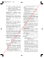 280
280
-
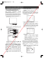 281
281
-
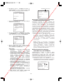 282
282
-
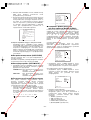 283
283
-
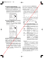 284
284
-
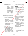 285
285
-
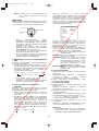 286
286
-
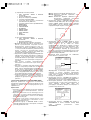 287
287
-
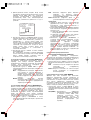 288
288
-
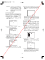 289
289
-
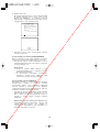 290
290
-
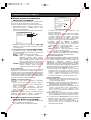 291
291
-
 292
292
-
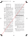 293
293
-
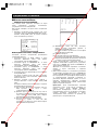 294
294
-
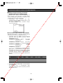 295
295
-
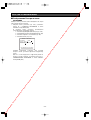 296
296
-
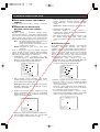 297
297
-
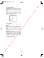 298
298
-
 299
299
-
 300
300
-
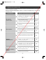 301
301
-
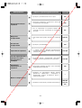 302
302
-
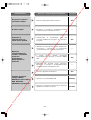 303
303
-
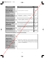 304
304
-
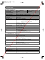 305
305
-
 306
306
-
 307
307


Panasonic WV-CS954E Operating Instructions Manual
- Categoria
- Telecamere di sicurezza
- Tipo
- Operating Instructions Manual
- Questo manuale è adatto anche per
in altre lingue
- English: Panasonic WV-CS954E
- français: Panasonic WV-CS954E
- español: Panasonic WV-CS954E
- Deutsch: Panasonic WV-CS954E
Documenti correlati
Altri documenti
-
Dedicated Micros 2000 Pan & Tilt Head Manuale del proprietario
-
Elvox Telecamera speed dome IR Speed Dome Istruzioni per l'uso
-
JVC TK-C625 Manuale utente
-
JVC TK-C553U - Fixed Color Dome Camera Manuale utente
-
-
Samsung SCC-B5397P Manuale utente
-
Trendnet TV-IP440PI Guida utente
-
Bosch Appliances VMD01 M50 PAL Manuale utente