Kromschroder IC 20 Poti Istruzioni per l'uso
- Tipo
- Istruzioni per l'uso

- 1 -
D
GB
F
NL
I
E
D
GB
F
NL
I
E
D
GB
F
NL
I
E
D
GB
F
NL
I
E
D
GB
F
NL
I
E
D
GB
F
NL
I
E
Alle in dieser Betriebsanleitung
aufgeführten Tätigkeiten dürfen
nur von autorisiertem Fach per-
sonal ausgeführt werden!
WARNUNG! Unsachgemäßer
Ein bau, Einstellung, Verän de rung,
Be die nung oder War tung kann
Ver letzungen oder Sachschäden
verursachen.
Anleitung vor dem Gebrauch lesen.
Dieses Gerät muss nach den
gelten den Vorschriften installiert
werden.
WARNING! Incorrect installation,
adjustment, modification, opera-
tion or maintenance may cause
injury or material damage.
Read the instructions before use.
This unit must be installed in ac-
cordance with the regulations in
force.
Toutes les actions mentionnées
dans les présentes instructions
de service doivent être exécu-
tées par des spécialistes formés
et autorisés uniquement !
ATTENTION ! Un montage, un ré-
glage, une modi fication, une utilisa-
tion ou un entretien in adaptés
risquent d’engendrer des dom-
mages matériels ou corporels.
Lire les instructions avant utilisa-
tion. Cet appareil doit être installé
en respectant les règlements en
vigueur.
Alle in deze bedrijfshandleiding
vermelde werkzaamheden mo-
gen alleen door technici worden
uitgevoerd!
WAARSCHUWING! Ondeskundi-
ge inbouw, instelling, wijziging,
bediening of onder houds werk zaam-
heden kunnen per soonlijk letsel of
materiële schade veroor zaken.
Aanwijzingen voor het gebruik lezen.
Dit apparaat moet overeenkom-
stig de geldende regels worden
geïnstalleerd.
Tutte le operazioni indicate nelle
presenti istruzioni d’uso devono
essere eseguite soltanto dal pre-
posto esperto autorizzato.
ATTENZIONE! Se montaggio,
re go lazione, modifica, utilizzo o
manu tenzione non vengono ese-
guiti correttamente, possono veri-
ficarsi infortuni o danni.
Si prega di leggere le istruzioni
prima di utilizzare il prodotto che
dovrà venire installato in base alle
normative vigenti.
¡Todas las actividades indica-
das en estas Instrucciones de
utiliza ción, sólo deben realizarse
por
una persona formada y auto-
rizada!
¡ADVERTENCIA! La instalación,
ajuste, modificación, manejo o
mantenimiento incorrecto puede
ocasionar daños personales o
mate riales.
Leer las instrucciones antes de
usar. Este dispositivo debe ser
instalado observando las normati-
vas en vigor.
TR CZ PL RUS H
DK S N P GR
www.kromschroeder.de
All the work set out in these
operating instructions may only
be completed by authorized
trained personnel!
Einbau
Potenziometer R.. für
Stellantrieb IC 20
Betriebsanleitung
Bitte lesen und aufbewahren
Zeichenerklärung
, , , ... = Tätigkeit
➔ = Hinweis
xx Fx/ivd
03250265
Edition 05.02
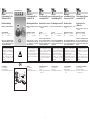
Prüfen
Lieferumfang
1 Potenziometer
2 Sicherungsring
3 Typenschild Potenziometer IC 20 1
3
2
D-49018 Osnabrück, Germany
R..
Zusatzausrüstung / Addit. Equipment
Vérifier
Programme de livraison
1 Potentiomètre
2 Circlip
3 Plaque signalétique du potentio-
mètre IC 20
Controleren
Leveringsomvang
1 Potentiometer
2 Borgring
3 Typeplaatje potentiometer IC 20
Verifica
Corredo di fornitura
1 Potenziometro
2 Anello di arresto
3 Targhetta dati per potenziometro
IC 20
Comprobar
Componentes del suministro
1 Potenciómetro
2 Anillo de seguridad
3 Placa de características del po-
tenciómetro IC 20
Testing
Delivery
1 Potentiometer
2 Locking ring
3 Type label potentiometer IC 20
Montage
Potentiomètre R.. pour
servomoteur IC 20
Instructions de service
À lire attentivement et à
conserver
Légendes
, , , ... = action
➔ = remarque
Inbouw
potentiometer R.. voor
stelaandrijving IC 20
Bedieningsvoorschrift
Lezen en goed bewaren a.u.b.
Legenda
, , , ... = werkzaamheden
➔ = aanwijzing
Montaggio
potenziometro R.. per
servomotore IC 20
Istruzioni d’uso
Si prega di leggere e conser-
vare
Spiegazione dei simboli
, , , ... = Operazione
➔ = Avvertenza
Montaje
Potenciómetro R.. para
servomotor IC 20
Instrucciones de
utilización
Se ruega que las lean y con-
serven
Explicación de símbolos
, , , ... = Actividad
➔ = Indicación
Installation
Potentiometer R.. for
actuator IC 20
Operating instructions
Please read and keep in a safe
place
Explanation of symbols
, , , ... = Action
➔ = Instruction

- 2 -
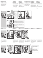
Einbau Potenziometer
Stellantrieb IC 20 in Nullstellung,
das heißt, die Drosselklappe BV
in geschlossene Stellung bringen.
Anlage spannungsfrei schalten.
Gas-/Luftzufuhr absperren.
Potenziometer austauschen/
nachrüsten
Am Potenziometer Mutter, Zahn-
scheibe und Unterlegscheibe
hochdrehen, damit sie beim Ein-
bauen auf der Halterung auflie-
gen.
7a 7c
7b
R..
D-49018 Osnabrück, Germany
R..
Zusatzausrüstung / Addit. Equipment
5
46
R..
D-49018 Osnabrück, Germany
R..
Zusatzausrüstung / Addit. Equipment
7
To install the
potentiometer
Set the actuator IC 20 to its zero
position, with the butterfly valve
BV in the closed position.
Disconnect the system from the
electrical power supply.
Shut off the supply of gas and air.
To replace/retrofit the
potentiometer
Screw up the nut, shakeproof
washer and washer onto the po-
tentiometer so that they are fitted
on the support during the instal-
lation process.
Montage du
potentiomètre
Mettre le servomoteur IC 20 en
position neutre, ce qui signifie
que la vanne papillon BV est en
position fermée.
Mettre l’installation hors tension.
Fermer l’alimentation gaz et air.
Remplacer/Monter le potentio-
mètre
Sur le potentiomètre, soulever
en tournant l’écrou, la rondelle à
dents chevauchantes et la ron-
delle plate afin qu’ils reposent sur
la fixation pendant le montage.
Inbouw potentiometer
Stelaandrijving IC 20 in nulstand,
dat wil zeggen: gasklep BV in ge-
sloten stand brengen.
Installatie spanningsvrij maken.
Gas-/luchttoevoer afsluiten.
Potentiometer vervangen/ach-
teraf verder uitrusten
Op de potentiometer moer, tand-
ring en onderlegring omhoog
draaien zodat ze bij het inbouwen
op de houder opliggen.
Montaggio del
potenziometro
Servomotore IC 20 in posizione
iniziale (di zero) ovvero chiudere la
valvola a farfalla BV.
Togliere la tensione dall’impianto.
Interrompere l’alimentazione del
gas/dell’aria.
Sostituzione/allestimento del
potenziometro
Avvitare sul potenziometro, in
alto, madrevite, rosetta elastica
dentata e rondella, in modo che
al momento del montaggio si tro-
vino sul supporto.
Montaje del
potenciómetro
Poner el servomotor IC 20 en po-
sición cero, es decir, situar la vál-
vula de mariposa BV en posición
cerrada.
Desconectar y dejar sin tensión la
instalación.
Cerrar el suministro de gas y de
aire.
Cambiar/montar posteriormente
el potenciómetro
En el potenciómetro girar la tuer-
ca, la rueda dentada y la arande-
la, para que al realizar el montaje
se apoyen sobre el soporte.
Nullposition prüfen.
Check the zero
position.
Vérifier la position
neutre.
Nulstand controleren.
Controllare la posi-
zione iniziale (di zero).
Comprobar la posi-
ción cero.
10
R..
D-49018 Osnabrück, Germany
R..
Zusatzausrüstung / Addit. Equipment
11 12
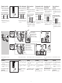
9Bis kurz vor Anschlag drehen.
Keep turning them until just before the
stop.
Tourner jusqu’à une position située
juste avant la butée.
Tot vlak voor de aanslag draaien.
Avvitare fino a poco prima dell’arresto.
Girar hasta poco antes del tope.
Sicherungsring und Wellenzahnscheibe mit Kraft etwas hoch-
schieben.
Slide locking ring and shakeproof washer firmly upwards a bit.
Pousser le circlip et la roue dentée légèrement vers le haut avec
force.
Borgring en afstandwiel met kracht wat omhoog schuiven.
Spingere l’anello di arresto e l’ingranaggio dell’albero con forza
un poco verso l’alto.
Empujar el anillo de seguridad y la rueda dentada del eje con fuer-
za un poco hacia arriba.

- 3 -
1
+
0
−
Ω
R..
D-49018 Osnabrück, Germany
R..
Zusatzausrüstung / Addit. Equipment
4
+
0
−
Ω
2
5
3
Startwert einstellen
Ohmwert zwischen der gelben
und roten Leitung oder zwischen
den Klemmen 19 und 20 messen
und den Startwert einstellen.
Bereich des einzustellenden
Startwertes am Potenziometer
Wider- Maximale Startwert-
stands- Spannung bereich 0°
nennwert
1000 Ω 20 V 20 – 80 Ω
➔ Widerstandsnennwert des Po-
tenziometers – siehe Typenschild
Potenziometer IC 20.
➔ Alle Einstellungen sind abge-
schlossen.
Verdrahten
➔ Der sich ändernde Widerstands-
wert wird als Stellungsrückmel-
dung genutzt.
➔ Die Leistungsaufnahme für das
Potenziometer beträgt maximal
0,5 Watt.
Das Potenziometer ist nachge-
rüstet worden:
Klemmen 18...20 verdrahten.
20 19 18
Ω
M
To set the starting value
Measure the Ohm value between
the yellow and red cables or be-
tween terminals 19 and 20 and
set the starting value.
Range for the starting value to
be set on the potentiometer
Rated Maxi- Starting
resistance mum value
value voltage range at 0°
1000 Ω 20 V 20 to 80 Ω
➔ See the type label on the poten-
tiometer IC 20 for its rated resist-
ance value.
➔ This completes all the settings.
Wiring
➔ The changing resistance value is
used as a position feedback sig-
nal.
➔ The power consumption for the
potentiometer is a maximum of
0.5 W.
If the potentiometer has been
retrofitted:
Wire terminals 18...20.
Régler la valeur de
départ
Mesurer la valeur ohmique entre
les fils jaune et rouge ou entre les
bornes 19 et 20 et régler la valeur
de départ.
Plage de la valeur de départ
pouvant être réglée sur le
potentiomètre
Valeur Tension Plage de
nominale maxi- la valeur
de la mum de dé-
résistance part 0°
1000 Ω 20 V 20 à 80 Ω
➔ Valeur nominale de la résistance
du potentiomètre – voir la plaque
signalétique du potentiomètre
IC 20.
➔ Tous les réglages sont terminés.
Câblage
➔ La valeur de résistance chan-
geante est utilisée comme reco-
pie de position.
➔ La puissance absorbée par le
potentiomètre est de 0,5 Watt
maximum.
Le potentiomètre a été monté :
Câbler les bornes 18...20.
Beginwaarde instellen
Ohmwaarde tussen de gele en
rode draad of tussen de klemmen
19 en 20 meten en de beginwaar-
de instellen.
Bereik van de in te stellen begin-
waarden op de potentiometer
Nominale Maxi- Begin-
weerstands- male waarde
waarde span- bereik 0°
ning
1000 Ω 20 V 20 tot 80 Ω
➔ Nominale weerstandswaarde van
de potentiometer – zie typeplaatje
potentiometer IC 20.
➔ Alle instellingen zijn voltooid.
Bedraden
➔ De zich wijzigende weerstands-
waarde wordt als standaanwijzer
benut.
➔ Het door de potentiometer opge-
nomen vermogen bedraagt maxi-
maal 0,5 watt.
De potentiometer is achteraf
omgebouwd:
Klemmen 18...20 bedraden.
Impostazione del
valore iniziale
Misurare il valore in ohm tra il con-
duttore giallo e il conduttore rosso
oppure tra i morsetti 19 e 20 e im-
postare il valore iniziale.
Limiti del valore iniziale da im-
postare sul potenziometro
Valore no- Ten- Limiti del
minale di sione valore
resi stenza massi- iniziale
ma a 0°
1000 Ω 20 V da 20 a 80 Ω
➔ Valore nominale di resistenza del
potenziometro – vedi targhetta
dati potenziometro IC 20.
➔ Sono state effettuate tutte le re-
golazioni.
Cablaggio
➔ Il valore di resistenza variabile
si utilizza come segnalazione di
conferma della posizione.
➔ La potenza massima assorbita
dal potenziometro è 0,5 watt.
Il potenziometro è stato allestito
in un secondo momento:
cablare i morsetti 18...20.
Ajuste del valor de
arranque
Medir el valor óhmico entre el ca-
ble amarillo y el rojo o entre los
bornes 19 y 20, y ajustar el valor
de arranque, es decir, la posición
mínima.
Rango del valor de arranque
que se debe ajustar en el poten-
ciómetro
Valor no- Ten- Rango
minal de sión del valor
la resisten- máxi- de arran-
cia ma que 0°
1000 Ω 20 V 20 hasta 80 Ω
➔ Valor nominal de la resistencia
del potenciómetro – ver placa de
características del potenciómetro
IC 20.
➔ Han finalizado todos los ajustes.
Cableado
➔ El valor cambiante de la resisten-
cia se utiliza como confirmación
de la posición.
➔ La potencia que consume el po-
tenciómetro es como máximo de
0,5 watios.
El potenciómetro se ha montado
posteriormente:
Cablear los bornes 18...20.
Startwert einstellen.
Set the starting value.
Régler la valeur de départ.
Beginwaarde instellen.
Impostare il valore iniziale.
Ajustar el valor de arranque.
Startwert überprüfen.
Check the starting value.
Vérifier la valeur de départ.
Beginwaarde controleren.
Controllare il valore iniziale.
Comprobar el valor de arranque.
20 19 18
Ω
M

- 4 -
Se reserva el derecho a realizar modi-
ficaciones técnicas sin previo aviso.
Puede recibir soporte técnico en la
sucursal/representación que a Ud. le
corresponda. La dirección la puede
obtener en Internet o a través de la
empresa
Elster GmbH
.
Salvo modifiche tecniche per migliorie.
Per problemi tecnici rivolgersi alla
filiale/rappresentanza competente.
L’indirizzo è disponibile su Internet o
può essere richiesto alla
Elster GmbH
.
Technische wijzigingen ter verbetering
van onze producten voorbehouden.
Voor technische vragen wendt u zich
a.u.b. tot de plaatselijke vestiging/ver-
tegenwoordiging. Het adres is op het
internet te vinden of u wendt zich tot
Elster GmbH
.
Sous réserve de modifications
techniques visant à améliorer nos
produits.
Pour toute assistance technique,
vous pouvez également contacter
votre agence/représentation la plus
proche dont l’adresse est disponible
sur Internet ou auprès de la société
Elster GmbH
.
We reserve the right to make technical
modifications in the interests of pro-
gress.
If you have any technical questions
please contact your local branch
office/agent. The addresses are
available on the Internet or from
ElsterGmbH
.
Elster GmbH
Strotheweg 1
D-49504 Lotte (Büren)
Tel. +49 (0)541 1214-0
Fax +49 (0)541 1214-370
www.kromschroeder.de
Technische Änderungen, die dem
Fortschritt dienen, vorbehalten.
Bei technischen Fragen wenden Sie
sich bitte an die für Sie zuständige
Nieder lassung/Vertretung. Die Adres-
se erfahren Sie im Internet oder bei der
Elster GmbH.
Zentrale Kundendienst-Einsatz-
Leitung weltweit:
Elster GmbH
Tel. +49 (0)541 1214-365
Tel. +49 (0)541 1214-499
Fax +49 (0)541 1214-547
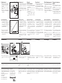
Funktionstest
➔ Empfohlen wird ein Funktionstest
im Handbetrieb durchzuführen.
Spannung an Klemme 3 und 4
anlegen.
Schalter S10 auf Handbetrieb
stellen.
Tippschalter S11 betätigen –
Öffnungs- und Schließverhalten
überprüfen.
Potenziometerbereich
➔ Der verfügbare Stellbereich des
Potenziometers hängt von den
Einstellungen der Schaltnocken
ab – siehe Betriebsanleitung
„Stellantrieb IC 20, IC 40, IC 40S,
Drosselklappe BVG, BVGF, BVA,
BVAF, BVH, BVHS“.
➔ Probelauf nicht in Ordnung – Ein-
stellungen neu vornehmen.
Probelauf in Ordnung – Stellan-
trieb, Schalter S10 wieder auf
Automatik stellen.
Zusammenbau
Typenschild Potenziometer IC 20
sichtbar am Stellantrieb aufkle-
ben.
0 90°
90° 0
S11S10
Ohm
100%
90°0°
50%
Function test
➔ We recommend that you conduct
the function test in manual mode.
Apply voltage to terminals 3 and
4.
Set switch S10 to manual mode.
Press the toggle switch S11 –
check the opening and closing
behaviour.
Potentiometer range
➔ The available setting range of
the potentiometer depends on
the settings of the switching
cams– see operating instructions
“Actuators IC 20, IC 40, IC 40S,
Butterfly valves BVG, BVGF, BVA,
BVAF, BVH, BVHS”.
➔ If the test does not produce the
desired result, repeat the setting
procedure.
If the test does produce the
desired result, set the actuator
switch S10 back to automatic
mode.
Assembly
Affix the type label for the poten-
tiometer IC 20 on the actuator
where it is clearly visible.
Essai de
fonctionnement
➔ Il est recommandé d’exécuter
un essai de fonctionnement en
mode manuel.
Mettre sous tension les bornes 3
et 4.
Mettre l’interrupteur S10 sur
mode manuel.
Actionner l’interrupteur à impul-
sion S11 – vérifier le comporte-
ment à l’ouverture et à la ferme-
ture.
Plage du potentiomètre
➔ La plage de réglage possible
du potentiomètre dépend des
réglages effectués sur les cames
de commutation – voir les ins-
tructions de service « Servomo-
teur IC20, IC 40, IC 40S, Vanne
papillon BVG, BVGF, BVA, BVAF,
BVH, BVHS».
➔ Essai de fonctionnement incor-
rect – recommencer les réglages.
Essai de fonctionnement cor-
rect – remettre l’interrupteur S10
sur le servomoteur en mode au-
tomatique.
Assemblage
Coller la plaque signalétique du
potentiomètre IC 20 sur le servo-
moteur de façon qu’elle soit bien
visible.
Functietest
➔ Aanbevolen wordt een functietest
in handbedrijf uit te voeren.
Spanning op klem 3 en 4 geven.
Schakelaar S10 op handbedrijf
zetten.
Tipschakelaar S11 bedienen –
open- en sluitgedrag controleren.
Potentiometerbereik
➔ Het beschikbare instelbereik van
de potentiometer hangt van de
instellingen van de schakelnok-
ken af – zie bedrijfshandleiding
“Stel aan drijving IC 20, IC 40,
IC 40S, Gasklep BVG, BVGF,
BVA, BVAF, BVH, BVHS”.
➔ Test niet in orde – instellingen op-
nieuw uitvoeren.
Test in orde – schakelaar S10 op
de stelaandrijving weer op auto-
maat zetten.
Assemblage
Typeplaatje potentiometer IC 20
zichtbaar op de stelaandrijving
plakken.
Test di funzionamento
➔ Si consiglia di effettuare un test
di funzionamento in modalità ma-
nuale.
Dare tensione ai morsetti 3 e 4.
Posizionare l’interruttore S10 sul
funzionamento manuale.
Azionare il pulsante S11 – con-
trollare il processo di apertura e di
chiusura.
Campo del potenziometro
➔ Il campo di regolazione disponi-
bile per il potenziometro dipende
dalle impostazioni delle camme
di commutazione – vedi Istruzioni
d’uso “Servomotori IC 20, IC 40,
IC 40S, Valvole a farfalla BVG,
BVGF, BVA, BVAF, BVH, BVHS”.
➔ Funzionamento di prova difetto-
so – eseguire di nuovo le regola-
zioni.
Funzionamento di prova perfet-
to – riposizionare l’in terrut tore
S10 del servomotore sul funzio-
namento automatico.
Assemblaggio
Incollare la targhetta dati del po-
tenziomentro IC 20 sul servomo-
tore, in modo che sia visibile.
Ensayo de funciona-
miento
➔ Se recomienda realizar un ensayo
de funcionamiento en operación
manual.
Aplicar tensión a los bornes 3 y 4.
Situar el interruptor S10 en posi-
ción de operación manual.
Accionar el interruptor de pulsa-
ción S11 – comprobar el com-
portamiento de apertura y cierre.
Rango del potenciómetro
➔ El campo de regulación disponi-
ble del potenciómetro depende
de los ajustes de las levas de
conmutación – ver Instrucciones
de utilización “Servomotor IC 20,
IC 40, IC 40S, Válvula de maripo-
sa BVG, BVGF, BVA, BVAF, BVH,
BVHS”.
➔ El funcionamiento de prueba no
es correcto – realizar de nuevo el
ajuste.
El funcionamiento de prueba es
correcto – en el servomotor, si-
tuar el interruptor S10 de nuevo
en posición de operación auto-
mática.
Ensamblaje
Pegar la placa de características
del potenciómetro IC 20 en un
lugar visible del servomotor.
2
1
R..
D-49018 Osnabrück, Germany
R..
Zusatzausrüstung / Addit. Equipment
D-49018 Osnabrück, Germany
R..
Zusatzausrüstung / Addit. Equipment
-
 1
1
-
 2
2
-
 3
3
-
 4
4


Kromschroder IC 20 Poti Istruzioni per l'uso
- Tipo
- Istruzioni per l'uso
in altre lingue
- français: Kromschroder IC 20 Poti Mode d'emploi
- español: Kromschroder IC 20 Poti Instrucciones de operación
- Deutsch: Kromschroder IC 20 Poti Bedienungsanleitung
- Nederlands: Kromschroder IC 20 Poti Handleiding


