
Das digitale DSI-Steuermodul ist zur Ansteuerung
von bis zu 50 digitalen Geräten z.B. elektroni-
schen Vorschalt geräten, Transformatoren oder
Phasendimmern konzipiert worden. Damit besitzt es alle
Eigenschaften die bisher von allen DSI-Geräten bereits
bekannt sind und es können die angeschlossenen
digitalen elektronischen Betriebsgeräte PCA/TE one4all/
PCD automatisch über die Steuerleitung geschaltet und
gesteuert werden.
Leitungstypen
Die Installation erfolgt mit Standardinstallations material.
Nach DIN VDE 0100/T520/Abschnitt 6 dürfen Haupt-
stromkreise und zugehörige Hilfsstromkreise gemeinsam
verlegt werden, auch wenn die Hilfsstromkreise eine
geringere Spannung führen als die Hauptstromkreise.
Dabei ist zu beachten, dass Kabel verwendet werden,
die der höchsten vorkommenden Betriebs spannung
entsprechen.
Als Busleitung wird eine verdrillte oder verseilte
2-Ader leitung (Empfehlung 2x1,5 mm²) verwendet, die
für Niederspannungsinstallation zugelassen ist. Die
Leitung muss für eine Prüfspannung von 4 kV zwischen
Adern und äußerer Manteloberfläche ausgelegt sein
(Prüfung nach DIN VDE 0472/Teil 508). Die Leitungen
sind nicht geschirmt. Ein Schlag pro Meter ist empfohlen,
ein Schlag pro 5 Meter ist Minimum.
z.B.:
H 05 VV-U 2x0,75 (NYM 2x0,75 mm² verdrillt)
H 05 VV-U 2x1,5 (NYM 2x1,5 mm² verdrillt)
J-Y(ST)Y mit bestandener 4 kV Prüfung
PYCYM 2 x 2 x 0,8 (Durchmesser) Achtung dies
entspricht 2 x 2 x 0,5 mm²
DSI-V/TINSTALLATION
article number/Artikelnummer: 28000882
11/14-1005-3 We reserve the right to make technical changes without prior notice.
Tridonic GmbH & Co KG, www.tridonic.com, [email protected], Tel. +43 5572 395-0
D
Technische Daten
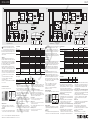
Funktionswahl DSI-V/T
DIP-Switch zur Wahl zwischen Funktion DSI-V oder DSI-T
Funktion Standard
•Standard:DasDSI-Signalwirdeingelesen,verstärkt
(Signal-Amplitude), aufgefrischt (zeitlich) und wieder
ausgegeben.
Funktion PC
•PC:DerRückkanalwirdamEingangdeaktiviertfürden
AnschlussderseriellenSchnittstelleRS232deswinDIM
Funktion Tunnel
•SicherheitsbetriebspeziellfürTunnelanwendungen.
Wird innerhalb von 60 Sekunden kein DSI-Signal mehr
empfangen, dimmt das DSI-V/T auf 100 % Helligkeit.
Der DSI-Stellwert 0 wird nur nach dreimaligem
Empfangen weitergeleitet (Erhöhung der Störfestigkeit).
Ein ungewolltes Ausschalten wird dadurch erschwert.
Weiter wird die Fehlerrückmeldung unterdrückt.
Funktion PD on/off
(Presence Detection/Präsenzerkennung)
•PD-Eingangwirdgeschlossen:DieBeleuchtungwird
sofort eingeschaltet. Der DSI-Stellwert dimmt auf den
Memory-Wert.
•PD-Eingangwirdgeöffnet:DieBeleuchtungdimmt
herunter und schaltet aus mit einer Fadetime =
60 Sekunden (bei einem DSI-Wert = 255).
PD only off (Presence Detection/Präsenzerkennung)
•PD-Eingangwirdgeschlossen:DieBeleuchtungwird
sofort eingeschaltet. Der DSI-Stellwert dimmt auf den
Memory-Wert.
•PD-Eingangwirdgeöffnet:DieBeleuchtungdimmt
herunter und schaltet aus mit einer Fadetime =
60 Sekunden (bei einem DSI-Wert = 255). Wenn nun
der Bewegungsmelder wieder Aktivität erkennt und
somit den PD-Eingang schließt, bleibt die Beleuchtung
trotzdem dunkel. Ein Einschalten der Beleuchtung ist
nur mittels dem externen Taster möglich. Wird dieser
nun betätigt, dimmt die Beleuchtung auf den letzten
eingestellten DSI-Wert.
PD never off (Presence Detection/Präsenzerkennung)
•PD-Eingangwirdgeschlossen.DieBeleuchtungwird
eingeschaltet. Der DSI-Stellwert dimmt die Beleuchtung
auf den letzten eingestellten DSI-Wert.
•PD-Eingangwirdgeöffnet.DieBeleuchtungdimmtauf
3 % herunter, es folgt kein AUS-Schalten. EIN/AUS-
Schalten ist nur mittels dem Einzel-/Doppeltaster
möglich.
Funktion Scene
•PD-Eingangwirdgeschlossen:AmPD-Eingangwirdein
Taster für den Szenen-Abruf angeschlossen.
Speicherung einer Szene
•langerTastendruck(>10Sekunden):Aktueller
DSI-Stellwert wird als Memory-Wert gespeichert.
•DiesewirddurcheinDoppel-Blinkenvon0,7Sekunden
(min.-max.-min.-max.) signalisiert.
Abruf der Szene
•kurzerTastendruck(50–600ms):Eswirddie
gespeicherte Szene (Memory-Wert) abgerufen.
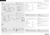
8–9mm
Drahtvorbereitung:
Volldraht0,5–1,5mm²
PD /Scene
159
147–150
30 21
30
** Einzeltastersteuerung
* Entweder Steuerung mit Bewegungsmelder oder Szenensteuerung über Taster
**
The digital DSI control module is designed to
control up to 50 digital units such as electronic
control gear, transformers and phase dimmers. It
there fore has all the properties shared by all DSI units so
far and enables PCA/TE one4all/PCD digital electronic
control gear to be automatically switched and controlled
via the control line.
Cable types
Standard installation and wiring material is used.
According to DIN VDE 0100/T520/Part 6, main circuits
and associated auxiliary circuits may be laid together
even if the auxiliary circuits carry a lower voltage than
the main circuits. Make sure to use cable designed to
take the maximum operating voltage.
A twisted or stranded 2-core cable approved for low-
voltage systems is used as the bus line (2x1.5 mm² is
recommended). The cable must be designed for a test
voltage of 4 kV between the wires and external sheath
surface (test in accordance with DIN VDE 0472/Part
508). The cables are not shielded. One twist per metre
is recommended; on per 5 metres is the minimum.
e.g.:
H 05 VV-U 2x0.75 (NYM 2x0.75 mm² twisted)
H 05 VV-U 2x1.5 (NYM 2x1.5 mm² twisted)
J-Y(ST)Y tested to 4 kV
PYCYM 2 x 2 x 0.8 (diameter) Note: this corresponds to
2 x 2 x 0.5 mm²
Technical data
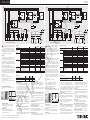
Function selection DSI-V/T
DIP switch for selecting DSI-V or DSI-T
Standard
PC
Tunnel
PD on/off
PD onlyoff
PD never off
Scene
12 3
DSI-VDSI-T
Standard function
•Standard:TheDSIsignalisreceived,amplified
(signal amplitude), refreshed (on a time basis) and
output again.
PC function
•PC:Thereturnchannelisdeactivatedattheinputfor
connectionoftheserialRS232interfaceofwinDIM
Tunnel function
•Safetymodespecificallyfortunnelapplications.IfaDSI
signal is not received within a period of 60 seconds,
the DSI-V/T will fade up to 100 % brightness. A DSI
value of 0 is forwarded only if the signal is received
three times in succession (this enhances the fault
tolerance of the system). This makes it difficult to
switch off the system inadvertently. Fault reporting
is also suppressed.
PD on/off function (Presence Detection)
•ThePDinputisclosed:Thelightingisswitchedon
immediately. The DSI value fades to the memory value.
•ThePDinputisopened:Thelightingfadesdownand
switches off with a fade time of 60 seconds (for a DSI
value of 255).
PD only off (Presence Detection)
•ThePDinputisclosed:Thelightingisswitchedon
immediately. The DSI value fades to the memory value.
•ThePDinputisopened:Thelightingfadesdownand
switches off with a fade time of 60 seconds (for a DSI
value of 255). If the presence detector now detects
activity again and therefore closes the PD input, the
lighting will still remain dark. The lighting can only be
switched on by means of the external switch. If this
switch is now actuated the lighting will fade up to the
last DSI value set.
PD never off (Presence Detection)
•ThePDinputisclosed.Thelightingisswitchedon.
The lighting fades up to the last DSI value set.
•ThePDinputisopened.Thelightingfadesdownto
3 %; it is not switch off. ON/OFF switching is possible
only with the one-way/two-way switch.
Scene function
•ThePDinputisclosed:Aswitchforretrieving
scenes is connected to the PD input.
Saving a scene
•Longpress(>10seconds):ThecurrentDSIvalueis
saved as the memory value.
•Thisissignalledbydoubleflashingfor0.7seconds
(min.-max.-min.-max.).
Retrieving a scene
•Shortpress(50-600ms):Thesavedscene
(memory value) is retrieved.
8–9 mm
Wire preparation:
Solid wire 0.5 – 1.5
PD/Scene
DSI signal
Switches
Presence
detector *
Preset
switch *
159
147 – 150
30 21
30
** Single pushbutton control
* Either control with presence detector or scene control via switches
**
UK
Standard
PC
Tunnel
PD on/off
PD onlyoff
PD never off
Scene
12 3
DSI-VDSI-T
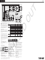
0.5 mm² 0.75 mm² 1.5 mm²
Built-in ceiling/luminaire modules 125 m 125 m 250 m
DSI signal amplifier (DSI-V) 125 m 125 m 250 m
Type DSI-T mode DSI-V mode
Article number: 28000882 28000882
Power supply: Mains voltage V120–277 120–277
Frequency Hz 50/60 50/60
Maximum output VA (W) < 1,0 < 1,0
Inputs: Switch –one-way/two-way –
Presence detector –yes –
Max. cable length to the switches m 100 –
Input voltage switch/PD V120–277 –
Frequency Hz 50/60 –
DSI signal – – DSI/winDIM
Outputs: DSI controller –1 1
Signal –digital/serial digital/serial
Voltage V 12 ±10 % 12 ±10 %
Data rate Bd 1200 1200
Control power per output PCA/TE one4all/PCD 50 50
Maximum cable length m 250 250
Cable length
definition:
Max. cable length for bridging in
tunnel mode (otherwise 250 m) for
min. 1.5 mm²
m–500
Temperature: Permissible ambient temperature °C -25 → +60 -25 → +60
Cable lengths
Typ DSI-T-Betrieb DSI-V-Betrieb
Artikelnummer: 28000882 28000882
Netzversorgung: Netzspannung V 120–277 120–277
Frequenz Hz 50/60 50/60
max. Leistung VA (W) < 1,0 < 1,0
Eingänge: Taster –einfach/doppel –
Bewegungsmelder –ja –
max. Leitungslänge zu den Tastern m 100 –
Eingangsspannung Taster/PD V120–277 –
Frequenz Hz 50/60 –
DSI-Signal – – DSI/winDIM
Ausgänge: DSI-Steuerung –1 1
Signal –digital/seriell digital/seriell
Spannung V 12 ±10 % 12 ±10 %
Datenrate Bd 1200 1200
Steuerleistung je Ausgang PCA/TE one4all/PCD 50 50
max. Leitungslänge m 250 250
Leitungslängen-
definition:
max. Leitungslänge für Überbrückung
im Tunnelmode (sonst 250 m) bei
min. 1,5 mm²
m–500
Temperatur: zulässige Umgebungstemperatur °C -25 → +60 -25 → +60
0,5 mm² 0,75 mm² 1,5 mm²
Decken-/Leuchteneinbaumodule 125 m 125 m 250 m
DSI-Signalverstärker (DSI-V) 125 m 125 m 250 m
Leitungslängen
PHASED OUT

DSI-V/TINSTALLATION
article number/Artikelnummer: 28000882
11/14-1005-3 We reserve the right to make technical changes without prior notice.
Tridonic GmbH & Co KG, www.tridonic.com, [email protected], Tel. +43 5572 395-0
Il modulo digitale DSI è concepito per comandare
un massimo di 50 apparecchi digitali come ad
esempio reattori e trasformatori elettronici o
dimmer fasici. Possiede dunque tutte le caratteristiche
dei moduli DSI conosciuti sino ad ora; inoltre accende
e comanda automaticamente i reattori digitali PCA/TE
one4all/PCD attraverso il cavo di comando.
Tipi di cavi
Per l’installazione si usa materiale standard. In confor-
mità alle norme DIN VDE 0100/T520/par. 6 i circuiti
di corrente principali e quelli ausiliari possono essere
condotti insieme anche se quelli ausiliari portano una
tensione minore di quelli principali. Si tenga presente
comunque che i cavi impiegati dovranno essere adatti
alla tensione d’esercizio più alta.
Per il bus si usa un cavo ritorto a 2 fili (si consiglia
2x1,5 mm²) omologato per installazioni a bassa tensione.
Il cavo deve essere predisposto per tensione di 4 kV fra
conduttori e rivestimento esterno (collaudo conf. DIN
VDE 0472/parte 508). I cavi non richiedono schermatura.
Si consiglia un avvolgimento per metro, uno per ogni
5 metri è il minimo.
Ad esempio:
H 05 VV-U 2x0,75 (NYM 2x0,75 mm² ritorto)
H 05 VV-U 2x1,5 (NYM 2x1,5 mm² ritorto)
J-Y(ST)Y con collaudo 4 kV
PYCYM 2 x 2 x 0,8 (sezione) Attenzione: corrisponde a
2 x 2 x 0,5 mm²
Dati tecnici
Scelta del funzionamento DSI-V/T
DIP-switch per scegliere tra funzionamento DSI-V
o DSI-T
Funzionamento standard
•Standard:ilsegnaleDSIvienelettoinmodo
rafforzato (ampliamento di segnale), ripetuto
(nel tempo) e riemesso.
Funzionamento PC
•PC:ilcanalediritornovienedisattivato
sull’ingresso per il collegamento all’interfaccia
serialeRS232delwinDIM.
Funzionamento tunnel
•Eserciziodisicurezzaperapplicazioniintunnel.Se
entro 60 secondi il modulo DSI-V/T non riceve nessun
segnale DSI, in altri 60 secondi porta la luminosità
al 100 % e continua a ripetere questo comando. Le
impostazioni DSI pari a 0 vengono trasmesse solo dopo
essere state ricevute per tre volte (maggior resistenza
ai disturbi). In questo modo si rende più difficile
spegnere l’impianto per sbaglio. Inoltre viene bloccata
la segnalazione di errori.
Funzionamento PD on/off
(Presence Detection / segnalazione di presenza)
•L’ingressoPDvienechiuso:l’illuminazionesiaccende
immediatamente. Il valore d’impostazione DSI si regola
su quello memorizzato.
•L’ingressoPDvieneaperto:l’illuminazionesiabbassa
fino a spegnersi in un tempo fading di 60 secondi
(255 con valore DSI).
PD only off
(Presence Detection / segnalazione di presenza)
•L’ingressoPDvienechiuso:l’illuminazionesiaccende
immediatamente. Il valore d’impostazione DSI si regola
su quello memorizzato.
•L’ingressoPDvieneaperto:l’illuminazionesiabbassa
fino a spegnersi in un tempo fading di 60 secondi
(255 con valore DSI). Se ora il segnalatore di pre-
senza riconosce un movimento e chiude l‘ingresso
PD, l’illuminazione rimane spenta comunque. Per
accenderla
si può ricorrere solo ad un pulsante esterno: in tal caso
la luce si accenderà regolandosi sull‘ultimo valore DSI
impostato.
PD never off
(Presence Detection / segnalazione di presenza)
•L’ingressoPDvienechiuso:l’illuminazionesiaccende
e si regola fino a raggiungere l’ultimo valore DSI
impostato.
•L’ingressoPDvieneaperto:l’illuminazionesiabbassa
fino al 3 % e NON si spegne. Per accendere/spegnere
si può usare solo un pulsante singolo o doppio.
Funzionamento Scene
•L’ingressoPDvienechiuso:all’ingressoPDèallacciato
un pulsante per richiamare le scene.
Memorizzazione di una scena
•Pressioneprolungatadelpulsante(>10secondi):
viene memorizzato il valore DSI attuale.
•L’operazioneèsegnalatadaundoppiolampeggiamento
di 0,7 secondi (min.-max.-min.-max.).
Richiamare una scena
•Pressionebrevedelpulsante(50–600ms):viene
richiamata la scena memorizzata (valore impostato).
8–9 mm
Predisposizione conduttore:
0,5 – 1,5
PD/Scene
Segnale DSI
Pulsante
Segnalatore
di presenza *
Tasto preset
opzionale *
159
147 – 150
30 21
30
** Regolazione tramite singolo pulsante
* Comando con segnalatore di presenza oppure comando di scene tramite pulsante.
**
I
Le module de commande numérique DSI-V/T
est conçu pour piloter jusqu’à 50 appareillages
numériques au maximum, par exemple des bal-
lasts, transformateurs ou gradateurs à coupure de phase.
Il possède donc toutes les caractéristiques propres aux
appareils DSI et permet de commuter et de piloter les
appareillages numériques connectés PCA/TE one4all/PCD
automatiquement via la ligne de commande.
Types de câbles
L’installation se fait avec du matériel électrique standard.
Conformément à la norme DIN VDE 0100/T520, section
6, les circuits électriques principaux et les circuits élec-
triques auxiliaires qui en font partie peuvent être posés
ensemble, même si les circuits auxiliaires véhiculent une
tension plus faible que les circuits principaux. On veillera
toutefois à utiliser des câbles dimensionnés pour la ten-
sion de fonctionnement la plus élevée du système.
Comme ligne de bus on utilisera un câble à 2 fils tor-
sadés ou toronnés (de préférence 2 x 1,5 mm²) autorisé
en installation basse tension. La ligne doit être conçue
pour une tension d’essai de 4 kV entre les brins et la
surface extérieure de la gaine (essai suivant DIN VDE
0472-508). Les lignes ne sont pas blindées. Pour le
commettage, le nombre recommandé est de 1 commet-
tage par mètre,
et le minimum de 1 tous les 5 mètres.
Exemple :
H 05 VV-U 2x0,75 (NYM 2x0,75 mm² torsadé)
H 05 VV-U 2x1,5 (NYM 2x1,5 mm² torsadé)
J-Y(ST)Y ayant satisfait à l’essai à 4 kV
PYCYM 2 x 2 x 0,8 (diamètre) Attention ! Ceci
correspond à 2 x 2 x 0,5 mm²
Caractéristiques techniques
Choix du fonctionnement DSI-V ou DSI-T
Switch DIP permettant de choisir entre le fonctionnement
DSI-V et DSI-T
Fonction standard
•Standard:lesignalDSIestlu,amplifié(amplitude),
régénéré (dans le temps) puis retransmis.
Fonction PC
•PC:lecanalretourestdésactivéàl’entréepour
raccorderl’interfacesérielleRS232duwinDIM
Fonction tunnel
•Modedefonctionnementsécuriséconçuspécialement
pour les tunnels : si aucun signal DSI n’est reçu en
l’espace de 60 secondes, le DSI-V/T met l’éclairage
en 60 secondes à son niveau d’intensité maximum
(100 %) et continue à répéter cette opération. Le signal
DSI zéro n’est retransmis qu’après avoir été reçu trois
fois (augmentation de la résistance aux perturbations),
ce qui rend plus difficile une extinction involontaire.
En outre, la signalisation des défauts est bloquée.
Fonction PD on/off
(PD = Presence Detection = détection de présence)
•EntréePDfermée:l’éclairageestimmédiatement
allumé. La valeur de consigne DSI met l’éclairage au
niveau mis en mémoire.
•EntréePDouverte:l’éclairagediminueprogressi-
vement d’intensité et s’éteint avec un fading de 60
secondes (pour une valeur DSI = 255).
PD only off
(PD = Presence Detection = détection de présence)
•EntréePDfermée:l’éclairageestimmédiatement
allumé. La valeur de consigne DSI met l’éclairage au
niveau mis en mémoire.
•EntréePDouverte:l’éclairagediminueprogressi-
vement d’intensité et s’éteint avec un fading de 60
secondes (pour une valeur DSI = 255). Dans ce mode
l’éclairage reste éteint même si le détecteur de
mouvements détecte une activité et ferme l’entrée PD.
Un allumage de l’éclairage ne peut se faire qu’avec
un poussoir externe. Lorsqu’un tel poussoir externe
est actionné, l’éclairage s’allume et se met au dernier
niveau DSI utilisé.
PD never off
(PD = Presence Detection = détection de présence)
•EntréePDfermée:l’éclairageestallumé.Lavaleur
de consigne DSI met l’éclairage au dernier niveau
DSI utilisé.
•EntréePDouverte:l’éclairagediminueà3%deson
intensité, SANS s’éteindre. Un ALLUMAGE/EXCTION ne
peut se faire qu’à partir du poussoir (simple ou double).
Fonction scénario
•EntréePDfermée:unpoussoirpourl’appelde
scénarios lumineux est connecté à l’entrée PD.
Mise en mémoire d’un scénario lumineux
•MémorisationdelavaleurDSIactuelleparunelongue
pression (pendant plus de 10 secondes) sur la touche.
•Lamiseenmémoireestconfirméeparundouble
clignotement de 0,7 seconde (min.-max.min.-max.).
Appel d’un scénario lumineux
•L’appeld’unscénariomémorisésefaitenappuyant
brièvement(50–600ms)surlatouche.
8–9 mm
Prépration du fil :
Fil plein de 0,5 à 1,5
PD/Scene
Signal DSI
Pulsante
Détecteur de
mouvements *
Bouton Preset
en option *
159
147 – 150
30 21
30
** Commande par bouton simple
* Soit commande par détecteur de mouvements soit commande par scénarios à l'aide d'un poussoir.
**
F
Standard
PC
Tunnel
PD on/off
PD onlyoff
PD never off
Scene
12 3
DSI-VDSI-T
Standard
PC
Tunnel
PD on/off
PD onlyoff
PD never off
Scene
12 3
DSI-VDSI-T
0,5 mm² 0,75 mm² 1,5 mm²
Moduli per soffitti/apparecchi 125 m 125 m 250 m
Amplificatore di segnale DSI (DSI-V) 125 m 125 m 250 m
Lunghezze cavi
Tipo Esercizio DSI-T Esercizio DSI-V
Codice articolo: 28000882 28000882
Alimentazione
di rete:
Tensione di rete V120–277 120–277
Frequenza Hz 50/60 50/60
Potenza max. VA (W) < 1,0 < 1,0
Entrate: Pulsante –singolo/doppio –
Segnalatore di presenza –si –
max. lungh. cavi fino ai pulsanti m 100 –
Tensione d’entrata pulsante/PD V120–277 –
Frequenza Hz 50/60 –
Segnale DSI – – DSI/winDIM
Uscite: Comando DSI –1 1
Segnale –digitale/seriale digitale/seriale
Tensione V 12 ±10 % 12 ±10 %
Quota dati Bd 1200 1200
Potenza comando per uscita PCA/TE one4all/PCD 50 50
max. lungh. cavi m 250 250
Definizione
lunghezze cavi:
max. lungh. cavi in caso di cavallotto
e modalità tunnel con sezione min.
1,5 mm² (altrimenti 250 m)
m–500
Temperatura: Temperatura ambiente ammessa °C -25 → +60 -25 → +60
0,5 mm² 0,75 mm² 1,5 mm²
Modules installés au plénum/en luminaire 125 m 125 m 250 m
Amplificateur de signal DSI (DSI-V) 125 m 125 m 250 m
Longueurs de lignes
Type Fonctionnement DSI-T Fonctionnement DSI-V
Référence 28000882 28000882
Alimentation
secteur
Tension secteur V120–277 120–277
Fréquence Hz 50/60 50/60
Puissance max. VA (W) < 1,0 < 1,0
Entrées Poussoir –simple/double –
Détecteur de présence –oui –
L max. ligne poussoir m 100 –
Tension d’entrée poussoir/PD V120–277 –
Fréquence Hz 50/60 –
Signal DSI – – DSI/winDIM
Sorties Commande DSI –1 1
Signal –numérique/sériel numérique/sériel
Tension V 12 ±10 % 12 ±10 %
Moyenne d’émissions Bd 1200 1200
Capacité de commande par sortie PCA/TE one4all/PCD 50 50
Longueur de ligne max. m 250 250
Déf. des
longueurs
de lignes
L max. pour le pontage en mode
tunnel (autrement 250 m) avec fil de
1,5 mm² min.
m–500
Température Temp. ambiante admissible °C -25 → +60 -25 → +60
PHASED OUT

DSI-V/T
INSTALLATION
article number/Artikelnummer: 28000882
11/14-1005-3 We reserve the right to make technical changes without prior notice.
Tridonic GmbH & Co KG, www.tridonic.com, [email protected], Tel. +43 5572 395-0
El equipo digital DSI-V/T Puede comandar hasta
50 equipos digitales de actuación por ejemplo
balastos, transformadores reguladores de corte de
fase. Dispone de las mismas caracteristicas que el resto
de equipos DSI-Digitales, pudiendo conectar de forma
compatible todos los actuadores digitales actuales como
PCA/TE one4all/PCD automáticamente en el mismo
BUS de comunicaciones y comandarlos.
Modelos de Conductores
La instalación se realiza con material estándar según
DIN VDE 0100/T520/Punto 6, pueden estar los conduc-
tores de potencia y los de control juntos incluso auque
las tensiones sean distintas tanto las de potencia como
las de control.
Debe asegurarse de utilizar el cable para la mayor
tensión de trabajo de cualquiera de los dos circuitos.
Se recomienda para el conductor del BUS 2-polos con-
ductores retorcidos (sección 2x1,5 mm²) homologado
para baja tension. Los conductores deben soportar 4 kV
entre los cobres y la superficie externa de acuerdo con la
normativa (Prueba DIN VDE 0472) Parte 508. No necesita
apantallamiento. Se recomienda una prueba por metro,
Minimum una prueba en cinco metros.
Por Ejemplo:
H 05 VV-U 2x0,75 (NYM 2x0,75 mm² retorcido)
H 05 VV-U 2x1,5 (NYM 2x1,5 mm² retorcido)
J-Y(ST)Y con prueba pasada de 4 kV
PYCYM 2 x 2 x 0,8 (Diametro) Atencion corresponde a
2 x 2 x 0,5 mm²
Datos Técnicos
Selector de Función DSI-V/T
DIP-Interruptores para función DSI-V o DSI-T
Función Standard (estándar)
•Estándar:LaseñalDSIseinterpreta,seamplifica
(señal-amplitud)sincroniza(entiempo)yseemite
de nuevo.
Función PC (ordenador personal)
•PC:Elcanalderetornosedesactivaparalasalida
informaticaRS232delprogramawinDIM.
Funcion Tunel
•Altaseguridaddefuncionamientoespecialparatune-
les.Sidurante60segundosnoserecibelaseñalDSI
el equipo DSI-V/T genera al cabo de 60 segundos una
señaldel100%deflujoylomantienepermanentey
solo alcanza el valor 0, si se reciben tres senales coin-
cidentes(aumentodeinmunidad).Seanulalaseñal
de desconexión. A la vez se mantiene sin actuar las
señalesderetro-información.
Función PD on/off (abierto/cerrado)
(detección de presencia)
•PD-Entradacerrada:elalumbradoseenciende
inmediatamente. El equipo DSI se ajusta al valor
memorizado.
•PD-Entradaabierta:Elalumbradodesciendeyllegaa
apagarse con un tiempo de bajada de 60 segundos
(desde el valor DSI = 255).
PD only off (solo abierto) (detección de presencia)
•PD-Entradacerrada:Elalumbradoseenciende
inmediatamente. El equipo DSI se ajusta al valor
memorizado.
•PD-Entradaabierta:Elalumbradodesciendehasta
apagarse con un tiempo de descenso = 60 segundos
(Desde un valor ajustado de DSI = 255, máximo). Pero
se activa de nuevo y se cierra el contacto del detector
de presencia, no obstante el alumbrado permanece
bajo. Solo se puede volver a encender mediante
el pulsador exterior. Si se actua este pulsador, el
alumbrado se ajusta al valor memorizado en el equipo
DSI-V/T.
PD never off (Nunca abierto) (detectector presencia)
•PD-Secierralaentrada.Seconectaelcircuito,el
equipo enciende con el ultimo valor ajustado en el
equipo DSI.
•PD-Seabrelaentrada.Elalumbradobajahastael3%,
pero no se desconecta. La conexion se realiza sola-
mente con los pulsadores exteriores sencillos o dobles.
Función Scene (Escena)
•SecierralaentradaPD:SellamaconelPulsador
Memorización de escena
•Pulsadalarga(>10segundos):Elajustedevaloren
el equipo DSI se memoriza.
•Seindicamedianteunadoblesenal0,7segundos
(min.-max.-min.-max.)
LLamada de escena
•Pulsadacorta(50–600ms):Sellamaalaescena
memorizada (valor ajustado).
8–9 mm
Preparacion Cable:
Rigido 0,5 – 1,5
PD/Escena
DSI-Señal
Pulsador
Detector de
Presencia *
Pulsador Preset
Opcional *
159
147 – 150
30 21
30
** Control por pulsador simple
* Mando por detector de presencia o Llamada a escenas con Pulsador
**
ESP
Standard
PC
Tunnel
PD on/off
PD onlyoff
PD never off
Scene
12 3
DSI-VDSI-T
0,5 mm² 0,75 mm² 1,5 mm²
Techo-/Montaje en luminaria 125 m 125 m 250 m
DSI-amplificadordeseñal(DSI-V) 125 m 125 m 250 m
Longitud conductores
Modelo DSI-T-Funcion DSI-V-Funcion
Código: 28000882 28000882
Alimentación: TensiónRED V120–277 120–277
Frecuencia Hz 50/60 50/60
Consumo max VA (W) < 1,0 < 1,0
Entradas: Pulsador –sencillo/doble –
Sensor presencia –Si –
max. Longitud hasta pulsador m 100 –
Tensión de pulsador / PD V120–277 –
Frecuencia Hz 50/60 –
DSI-Señal – – DSI/winDIM
Salidas: Control DSI –1 1
Señal – digital/serie digital/serie
Tensión V 12 ±10 % 12 ±10 %
Datos / segundo Bd 1200 1200
Número de equipos salida PCA/TE one4all/PCD 50 50
max. longitud cable m 250 250
Longitud BUS-
definición:
max. longitud de puenteo en modo
túnel (hasta 250 m) con min. 1,5
mm²
m–500
Temperatura: Entorno temperatura °C -25 → +60 -25 → +60
PHASED OUT
-
 1
1
-
 2
2
-
 3
3


in altre lingue
- français: Tridonic 28000882 Manuel utilisateur
- español: Tridonic 28000882 Manual de usuario
- Deutsch: Tridonic 28000882 Benutzerhandbuch
Documenti correlati

Altri documenti
-
CP Electronics EBDRC-DD Guida d'installazione
-
 Lutron Electronics LCP128 Guida d'installazione
-
CP Electronics EBMPIR-MB-DD Mini PIR Detector for Luminaire Integration Guida d'installazione
-
-
Nintendo DSi XL Manuale del proprietario
-
Nintendo New 3DS XL Manuale del proprietario
-
Hama Fluxity Manuale del proprietario
-
König GAM3DS-ADAPT10 specificazione
-
HELVAR 472 1-10 V / DSI Converter Guida d'installazione
-
 Thorn BasicDIM / CONTR TR CAS>DA0 #bDW Module Guida d'installazione

