DirekTronik 20115421 Manuale del proprietario

Categoria
Misurazione, test
Tipo
Manuale del proprietario

Questo manuale è adatto anche per

EN
DCM8500PV
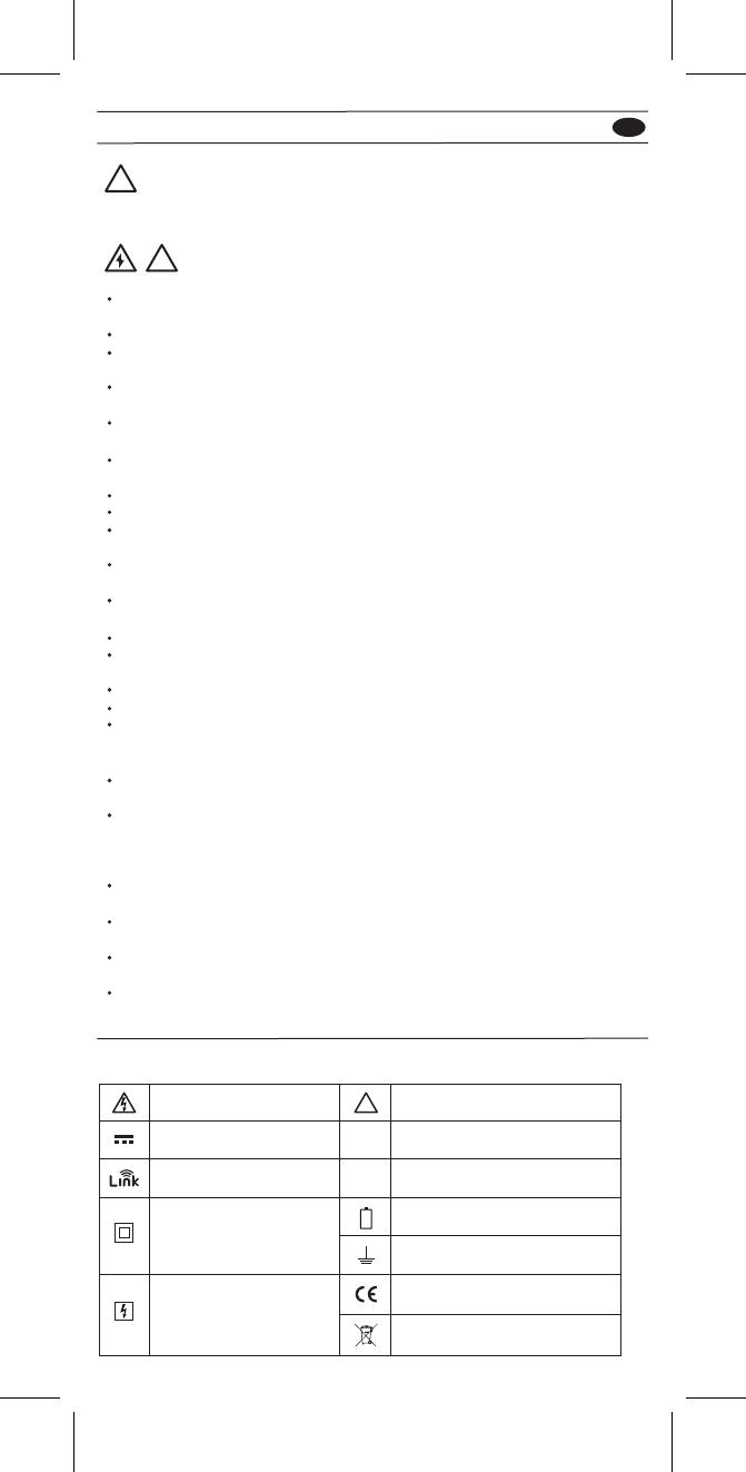
Symbols as marked on the Meter and Instruction manual
!Safety Information
Understand and follow operating instructions carefully. Use the meter only as.
WARNING
!
If the equipment is used in a manner not specified by the manufacturer, the
protection provided by the equipment may be impaired.
Always use proper terminals, switch position, and range for measurements.
To reduce the risk of fire or electric shock, do not use this product around
explosive gas or in damp locations.
Verify the Meter operation by measuring a known voltage. If in doubt, have the
Meter serviced.
Do not apply more than the rated voltage, as marked on Meter, between
terminals or between any terminal and earth ground.
To avoid false readings that can lead to electric shock and injury, replace the
battery as soon as low battery indicator blinks.
Avoid working alone so assistance can be rendered.
Do not use the Tester if the Tester is not operating properly or if it is wet.
Individual protective device must be used if hazardous live parts in the installation
where the measurement is to be carried out could be accessible.
Disconnect the test leads from the test points before changing the position of the
function rotary switch.
Never connect a source of voltage when the function rotary switch is not in
voltage position.
When using test leads or probes, keep your fingers behind the finger guards.
Use caution with voltages above 30 Vac rms, 42 Vac peak, or 60 Vdc. These
voltages pose a shock hazard.
Remove test lead from Meter before opening the battery door or Meter case.
DO NOT USE the test leads when the internal white insulation layer is exposed.
DO NOT USE the test leads above maximum ratings of CAT.
environment, voltage and current, that are indicated on the
probe and the probe tip guard cap.
DO NOT USE the test leads without the probe tip guard cap in CAT III and CAT IV
environments.
Probe assemblies to be used for MAINS measurements shall be RATED as
appropriate for MEASUREMENT CATEGORY III or IV according to IEC
61010-031 and shall have a voltage RATING of at least the voltage of the circuit
to be measured.
Disconnect circuit power and discharge all high-voltage capacitors before testing
resistance, continuity, diodes, or capacitance.
De-energize the installation under test or wear suitable protective clothing during
fitting and removal of the Flexible Current Probe.
Do not apply around or remove from UNINSULATED HAZARDOUS LIVE
conductors, which may render electric
shock, electric burn, or arc flash.
!
Risk of electric shock
Equipment protected by
double or reinforced
insulation
DC measurement
Low battery
Earth ground
AC measurement
Both direct and alternating currentWireless transmission
Conforms to EU directivesApplication around and
removal from hazardous
live conductors is permitted
See instruction manual
~
~
Do not discard this product or
throw away.
01
EN
DCM8500PV
Maintenance
Do not attempt to repair this Meter. It contains no user serviceableparts. Repair or
servicing should only be performed by qualified personnel.
Front Panel Illustration
1. JAW
2. Volt seek Light.
3. Push-buttons.
4. Trigger.
5. Rotary switch for turn the Power On / Off and select the function.
6. 6,000 count digital display.
7. Input Terminal for Multi-function.
8. Common (Ground reference) Input Terminal.
Cleaning
Periodically wipe the case with a dry cloth and detergent.
Do not use abrasives or solvents.
Introduction
The Meter Description
Unsafe Voltage
To alert you to the presence of a potentially hazardous voltage, when the Tester detects
a voltage 30 V or a voltage overload (OL) in V, mV, LoZ. The symbol is displayed.
1
2
3
5
6
7
4
3
8
JAW
Voltseek Light
Button
Rotary Switch
Display
"+" Input
Trigger
Button
Common input
Function button
02
EN
DCM8500PV
!CAUTION
When connecting the test leads to the DUT (Device Under Test) connect the common
test leads before connecting the live test leads ; when removing the test leads, remove
the live test leads before removing the common test leads.
Dial the switch to select the
measuring function.
Dial the switch and
press the Function button
to select AC/DC mode.
V
APO AC
V
APO
APO
DC
DC
mV
COM
Measuring Voltage
Measuring PV Voltage
V
APO AC
V
APO
DC
PV String
View side
COM
!CAUTION
This function is only available with the dedicated PV test probe.
Always select correct DC / AC mode to perform high voltage measurement. This meter
will flash symbol and the correct mode symbol (AC / DC) if the input voltage is
different and dangerous.
Making Basic Measurements
03
EN
DCM8500PV
Measuring Current
OK

OK
OK
I
APO
A
APO AC
A
DC
CAT.IV 600V
CAT.III 1000V
with respect to
earth for the jaw.
Tactile Barrier for
hand guard.
Do not hold
the meter across
the Barrier
COM
!
!
Dial the switch and press the Function button to select the measuring function.
Note : Torch will be on when jaw is opened.
Dial the switch and press the Function button to select the measuring function.
Measuring Resistance/Continuity/Capacitance/Diode
APO APO
k
APO
Volt seek
APO
V
APO
F
COM
04
EN
DCM8500PV
Dial the switch and press the Function button to select °C / °F mode.
Measuring Temperature °C / °F
APO
APO
C
F
Funtion
Button
COM
Dial the switch and press the Function button to select AC/DC mode.
Measuring μA
DC
AFlame
sensor
Control
Module

05
EN
DCM8500PV
A
AC
+
COM
Keep the range of Flex Clamp meter at 3000A/3V output ratio.
Measuring Current with Flex Clamp Meter
Press the Function button to
change the function on the
same switch position.
Using the Function
Measuring Frequency
Function
Position
Switch
°
Funtion
Button
AC AC
VHz Hz
06
EN
DCM8500PV
Press Function button for over 2 sec. to turn Backlight on / off.
Backlight
2 Sec
> 2 sec
Press
MIN/MAX
Volt Seek
MIN
MAX
MIN
MAX
V
V
AC
V
MIN
MAX
Press
MIN
MAX
Press
MAX MIN AC
MIN
MAX
AC
Press MIN
MAX Button > 2 sec
to exit the MINMAX mode
V
AC
Press
MIN
MAX
Press
The MAX/MIN mode records the min and max input values.
When the input goes below the recorded min value or above the recorded max value,
the meter records the new value. Press Hold button to pause the recording.
Press MIN/MAX button for over 2 sec. to enter / exit Volt Seek mode.
Press MIN/MAX button to switch high/low sensitivity.
!Warning
The Volt Seek LED indicates the electric field. If the Volt Seek LED is not on, voltage
could still be present.
MIN
MAX
MIN
MAX
AC
Volt seek
2 Sec
Volt seek
2 Sec
Do not hold across this
line when sensing the
hazardous voltage.
COM
Sensor
position
07
EN
DCM8500PV
Smart Hold
The meter will beep continuously and the display will flash if the measured signal is
larger than the display reading by 50 counts.
(However, it can not detect across the AC and DC Voltage / Current).
AC AC
HOLD
ZERO
A A
HOLD
HOLD
DCA ZERO
Remove the jaw from the conductor before performing DCA ZERO.
Press HOLD button for over 2sec. to compensate the residual magnetism.
APO
DC
A
ZeroAPO
DC
A
ZeroAPO
HOLD
ZERO
> 2 sec
Press
HOLD
ZERO
> 2 sec
Press DC
A
High Frequency Rejection (HFR)
The High Frequency Rejection mode equip a low pass filter in the AC measurements.
The cut-off frequency (-3dB point) of low pass filter is 800Hz.
HFR
HFR
AC
AC
HFR
Press
HFR
V
V
!Warning
The hazardous voltage may be present even if the LCD reading is very low in HFR
mode. Verify the voltage again without HFR mode
08
EN
DCM8500PV
INRUSH
In inrush current mode, select the suitable measurement range by pressing
HFR/INRUSH button before triggering the inrush current measurement.
12
A A
A
HFR
> 2 sec
Press
Watting Tigger
After Tigger
1
2
Inrush
2 Sec
HFR
> 2 sec
Press
Inrush
2 Sec
AC AC
AC
Auto Power Off
Wake up the meter by dialing the switch or pressing any button.
After Specified Time
Without Operation
09
EN
DCM8500PV
Time Setting of Auto Power Off
Testing LCD Monitor
Press the function button and turn the meter on. Then press the function button to
select the time. The time can be 5 minutes, 10 minutes, 20 minutes, and disabled
(OFF).
To turn on the meter after
keeping HOLD button down.
Funtion
Button
1
2 3
Funtion
Button
APO
HOLD
1
2
APO Zero MAXMIN HOLDAC
LOG HFR LOZ DC%
C°F
FA
mV
Hz
k
Function of LOG Button
Pressing button while powering-up to select the mode – Data Logger mode,
Manual Saving mode and Clear memory.
Press
12
3
Press
LOG
LOG
LOG
Press
Press
10
EN
DCM8500PV
Data Logger
The meter can store up to 4000 data in memory.
Press button for more than 2 seconds to activate Data logger mode. The meter
will enter Time interval setting mode.
Press button again to select time interval. The interval can be 1 second, 5
seconds, 10 seconds, 30 seconds, 60 seconds.
LOG
2 Sec
AC
V
Press
Press Press
LOG
LOG
S
S
V
AC
LOG
Press
Time interval setting mode
Start to record auto
matically after 2sec
without operaction.
LOG icon flashes while logging
LOG
2 Sec >2Sec
!CAUTION
All stored data will be cleared next startup. Download the stored data by App first if
needed.
Manual Saving Mode
!CAUTION
All stored data are saved until switching to data logger mode or executing the clear
function.
LOG
2 Sec
AC
V
LOG
V
AC
LOG
To save a reading
Show stored reading
amount for 2 seconds
HOLD
LOG Flash
Press
LOG
2 Sec >2Sec
11
EN
DCM8500PV
The meter uses Wireless low energy (BLE) V4.0 wireless technology to transfer the
real-time reading and the stored data.
The open-air communication range is up to 10m.
Download “KPS Link” App via the following QR Code. Turn on Bluetooth function of the
meter and open “KPS Link” to connect the DMM. The Bluetooth icon of the meter will
freeze on LCD after the connection establishes successfully.
AC
Press
AC
VV
Default Temperature Units Setting
Turn on the meter after keeping MIN/MAX button down.
C
F
OR
1
2
COM
MIN
MAX
MIN
MAX
12
EN
DCM8500PV
Low Battery and Battery Replacement
!Warning
Remove test leads from Meter before opening the battery cover or Meter case.
1
2
3
Specifications
CAT Application field
General Specifications
Display : 6000 counts.
Overrange Indication : ”OL” or “-OL”
Measure : Samples 3 times per second .
Max Conductor Size of JAW : 37mm diameter
Dimensions (W x H x D) : 62mm x 240mm x 41mm
Weight : approx. 430g (including battery)
Low Batteries Indication : Voltage drops below operating voltage will flash.
Power Requirement : AA Size Battery x 2 (R6, LR6, 15D, 15A)
Battery Life : 200 hours ALKALINE Battery (without Backlight)
Operating Temperature : -10 ~10°C
10°C ~ 30°C (80% RH),
30°C ~ 40°C (75% RH),
40°C ~ 50°C (45%RH)
Storage Temperature : -20°C to 60°C , 0 to 80% R.H. (batteries not fitted)
Altitude : 6561.7 ft (2000m)
Safety : EN 61010-1, EN 61010-2-032, EN 61010-2-033 for CAT III 1000V, CAT IV
600V, EN 61326-1
Drop Protection : 4 feet drop to hardwood on concrete floor
Vibration : Random Vibration per MIL-PRF-28800F Class 2
Pollution degree : 2
Indoor Use
The building installation.
The circuits directly connected to Low-voltage installation.
The source of the Low-voltage installation.
13
EN
DCM8500PV
(1) Temperature coefficient
0.2 x (Specified accuracy) / °C, < 18°C, > 28°C
(2) AC Function
ACV and ACA specifications are ac coupled, true R.M.S.
The crest factor may be up to 3.0 as 4000 counts.
Accuracy is unspecified of Square Wave.
For non-sinusoidal waveforms, Additional Accuracy by
Crest Factor (C.F.) :
Add 3.0% for C.F. 1.0 ~ 2.0.
Add 5.0% for C.F. 2.0 ~ 2.5.
Add 7.0% for C.F. 2.5 ~ 3.0.
Max. Crest Factor of Input Signal:
3.0 @ 3000 counts
2.0 @ 4500 counts
1.5 @ 6000 counts
Frequency Response is specified for sine waveform.
LCD displays 0 counts when the reading < 20 counts.
Electrical Specifications
Accuracy is given as ± (% of reading + counts of least significant digit) at 23°C ± 5°C,
with relative humidity Less than 80% R.H., and is specified for 1 year after calibration.
(3) DC mV
SInput Impedance : 10MΩ
Overload Protection : AC/DC 1000V
Range OL Reading Resolution Accuracy
600.0mV 660.0mV 0.1mV ± (0.7% + 5D)
(4) DC Voltage
SInput Impedance : 10MΩ
Overload Protection : AC/DC 1000V
Range OL Reading Resolution Accuracy
600.0V 660.0V 0.1V
1000V 1100V 1V
±(0.7% + 2D)
(5) AC Voltage
Input Impedance : 10MΩ // less than 100pF
Frequency Response : 45 ~ 400Hz (Sine Wave)
Overload Protection : AC/DC 1000V
Range OL Reading Resolution Accuracy
600.0V 660.0V 0.1V
1000V 1100V 1V
±(1.0% + 5D)
(6) PV DC Voltage
Input Impedance : 10MΩ
Overload Protection : AC/DC 1000V
Range OL Reading Resolution Accuracy
600.0V 660.0V 0.1V
2000V 2200V 1V
±(2.0% + 5D)
14
EN
DCM8500PV
(7) PV AC Voltage
Frequency Response : 45 ~ 400Hz (Sine Wave)
Input Impedance : 10MΩ // less than 100pF
Overload Protection : AC/DC 1000V
Range OL Reading Resolution Accuracy
600.0V 660.0V 0.1V
1500V 1600V 1V
±(2.0% + 5D)
(8) AC/DC μA
Input Impedance : Approx. 2.2kΩ
Frequency Response : 45 ~ 400Hz (Sine Wave)
Overload Protection : AC/DC 1000V
Range OL Reading Resolution Accuracy
400.0μA 440.0μA 0.1μA
4000μA 4400μA 1μA
±(1.0% + 3D)
(9) DC Current
The measured value <5.0A, add 10 dgt to the accuracy.
The measured value >1000A, add 0.5% to the accuracy.
Overload Protection : AC/DC 600A
Range OL Reading Resolution Accuracy
60.00A 66.00A 0.01A
600.0A 660.0A 0.1A
±(2.0% + 5D)
(10) AC Current
Add 10 dgt to the accuracy when <5.0A.
Add 0.5% to the accuracy when >1000A.
Add 1% to the accuracy when >100Hz.
Frequency Response : (Sine Wave) 45 ~ 400Hz
Overload Protection : AC/DC 600A
Range OL Reading Resolution Accuracy
60.00A 66.00A 0.01A
600.0A 660.0A 0.1A
±(2.0% + 5D)
(11) Flexible Current Probe
Frequency Response : 45Hz to 400Hz
Accuracy does not include accuracy of the Flexible Current Probe.
Overload Protection : AC/DC 1000V
Range OL Reading Resolution Accuracy
300.0A 330.0A 0.1A
3000A 3300A 1A
±(1.5% + 5D)
15
EN
DCM8500PV
(12) Frequency
Minimum Sensitivity :
> 5V (for ACV 1Hz ~ 10kHz)
> 8A (for ACA 1Hz ~ 1kHz)
Minimum Frequency : 1Hz
Overload Protection : AC/DC 1000V and 600A
(13) HFR (High Frequency Rejection)
Available for ACV, ACA and, Flexible Current Probe.
Add ± 4% to specified accuracy of each function and each range for 45Hz to 200Hz.
Accuracy is unspecified for > 200Hz.
Cut-off Frequency (-3dB) : 800Hz
(14) Inrush Current
Available for ACA and Flexible Current Probe.
Trigger level : 50d.
Add ± 3% to specified accuracy of each function and each range.
Range OL Reading Resolution Accuracy
100.00Hz 100.00Hz 0.01Hz
1000.0Hz 1000.0Hz 0.1Hz
10.000kHz 10.000kHz 0.001kHz
±(0.3% + 3D)
(15) Resistance
To get more accuracy result, short the test probes to obtain the offset. The accuracy
specification is specified for the result that the offset is subtracted.
Overload Protection : AC/DC 1000V
(16) Continuity
Built-in buzzer sounds when measured resistance is less than 20Ω and sounds off
when measured resistance is more than 200Ω, Between 20Ω to 200Ω the buzzer
maybe sound or off either.
Continuity Indicator : 2.7K Tone Buzzer
Response Time of Buzzer : < 100msec.
Overload Protection : AC/DC 1000V
Range OL Reading Resolution Accuracy
600.0Ω 660.0Ω 0.1Ω ±(0.9% + 5D)
6.000kΩ 6.600kΩ 0.001kΩ
600.0kΩ 660.0kΩ 0.1kΩ
60.00kΩ 66.00kΩ 0.00kΩ ±(0.9% + 2D)
Open Circuit Voltage : Approx. 1.8V
Overload Protection : AC/DC 1000V.
(17) Diode
Range OL Reading Resolution Accuracy
1.500V 1.550V 0.001V ±(0.9% + 2D)
16
EN
DCM8500PV
(18) Capacitance
Range OL Reading Resolution Accuracy
100.0μF 110.0μF 0.1μF
1000μF 1100μF 1μF
±(1.9% + 2D)
(20) Temperature
Range OL Reading Resolution Accuracy
-40.0°C – 400.0°C 440.0°C 0.1°C
-40.0°F – 752.0°F 824.0°F 0.1°F
±(1% + 20D)
±(1% + 36D)
Overload Protection : AC/DC 1000V
(19) VoltSeek
Voltage Range of High Sensitivity : 80V ~ 1000V (At the top edge of the jaw)
Voltage Range of Low Sensitivity : 160V ~ 1000V (At the top edge of the jaw)
The accuracy does not include the accuracy of the thermocouple probe.
Accuracy specification assumes surrounding temperature stable to ±1°C. For
surrounding temperature changes of ± 2°C, rated accuracy applies after 2 hours.
Overload Protection : AC/DC 1000V
17
EN
DCM8500PV
!CAUTION
Make sure that test leads are firmly connected to the V-COM terminals of the correct
instrument, and the instrument have to switch to PV mode.
ATL-PV Test Leads Instruction
Probe tip guard cap
For CAT III or CAT IV environments, use the test leads with the probe tip guard cap
fixed firmly. Without the probe tip guard cap, the test leads can be used in
CAT II environment ONLY.
For 1500V AC & 2000V DC measurement, This test lead can only be used in the
environment that is not connected to MAINS directly.
Finger Guard
18
EN
DCM8500PV
!CAUTION
When using test leads or probes, keep your fingers behind the finger guards.
Use caution with voltages above 30 Vac rms, 42 Vac peak, or 60 Vdc. These voltages
pose a shock hazard.
If the test lead is used in a manner not specified by the manufacturer, the protection
provided by the equipment may be impaired.
To reduce the risk of fire or electric shock, do not use this product around explosive
gas or in damp locations.
DO NOT USE the test leads when the internal white insulation layer is exposed.
DO NOT USE the test leads above maximum ratings of CAT. environment, voltage and
current, that are indicated on the probe and the probe tip guard cap.
DO NOT USE the test leads without the probe tip guard cap in CAT III and CAT IV
environments.
DO NOT USE the test leads to measure over 1000V that is connected to MAINS
directly.
Maintenance
Do not attempt to repair this test lead set. It contains no user-serviceable parts. Repair
or servicing should only be performed by qualified personnel.
Cleaning
Clean the test lead with a water and mild detergent. DO NOT use abrasives or
solvents and DO NOT IMMERSE in liquid.
Specification
Input Impedance: 10MΩ
Overvoltage Category: CAT 0 1500V AC, 2000V DC
CAT II 1000V AC, 1500V DC
CAT III 1000V, CAT IV 600V.
Pollution Degree 2
Exposed probe tip length : 19 mm to 4 mm (0.75 inch to 0.16 inch)
Environmental ratings : -10°C to 45°C (-4°F to 113°F), 80% R.H.
Altitude : 2000 m (6,562 ft)
Safety Standard : EN61010-031
CAT Application field
The building installation.
The circuits directly connected to Low-voltage installation.
The source of the Low-voltage installation.
Circuits that are not directly connected to Mains
Symbols as marked on the test lead and Instruction card
!
Risk of electric shock
DC measurement
Earth ground
AC measurement
Both direct and alternating current
Conforms to EU directives
See instruction Card
~
~
Equipment protected by double
or reinforced insulation
19
  • Page 1 1
  • Page 2 2
  • Page 3 3
  • Page 4 4
  • Page 5 5
  • Page 6 6
  • Page 7 7
  • Page 8 8
  • Page 9 9
  • Page 10 10
  • Page 11 11
  • Page 12 12
  • Page 13 13
  • Page 14 14
  • Page 15 15
  • Page 16 16
  • Page 17 17
  • Page 18 18
  • Page 19 19
  • Page 20 20
  • Page 21 21
  • Page 22 22
  • Page 23 23
  • Page 24 24
  • Page 25 25
  • Page 26 26
  • Page 27 27
  • Page 28 28
  • Page 29 29
  • Page 30 30
  • Page 31 31
  • Page 32 32
  • Page 33 33
  • Page 34 34
  • Page 35 35
  • Page 36 36
  • Page 37 37
  • Page 38 38
  • Page 39 39
  • Page 40 40
  • Page 41 41
  • Page 42 42
  • Page 43 43
  • Page 44 44
  • Page 45 45
  • Page 46 46
  • Page 47 47
  • Page 48 48
  • Page 49 49
  • Page 50 50
  • Page 51 51
  • Page 52 52
  • Page 53 53
  • Page 54 54
  • Page 55 55
  • Page 56 56
  • Page 57 57
  • Page 58 58
  • Page 59 59
  • Page 60 60
  • Page 61 61
  • Page 62 62
  • Page 63 63
  • Page 64 64
  • Page 65 65
  • Page 66 66
  • Page 67 67
  • Page 68 68
  • Page 69 69
  • Page 70 70
  • Page 71 71
  • Page 72 72
  • Page 73 73
  • Page 74 74
  • Page 75 75
  • Page 76 76
  • Page 77 77
  • Page 78 78
  • Page 79 79
  • Page 80 80
  • Page 81 81
  • Page 82 82
  • Page 83 83
  • Page 84 84
  • Page 85 85
  • Page 86 86
  • Page 87 87
  • Page 88 88
  • Page 89 89
  • Page 90 90
  • Page 91 91
  • Page 92 92
  • Page 93 93
  • Page 94 94
  • Page 95 95
  • Page 96 96
  • Page 97 97
  • Page 98 98

DirekTronik 20115421 Manuale del proprietario

Categoria
Misurazione, test
Tipo
Manuale del proprietario
Questo manuale è adatto anche per