

®
Q - S e r i e s V i d e o M o d u l e s P r o d u c t M a n u a l , R e v . I
Page 2
Copyright Notice
Copyright © 2015. All rights reserved. Printed in the U.S.A.
Thinklogical, LLC®
100 Washington Street
Milford, Connecticut 06460 U.S.A.
Telephone: 1-203-647-8700
All trademarks and service marks are property of their respective owners.
Q-Series Chassis
& Modules
®
Subject: Velocity Q-Series Video Modules Product Manual
Release: Rev. I, February, 2015
2014
2013
Website: www.thinklogical.com
Facebook: www.facebook.com/ThinklogicalUSA
LinkedIn: www.linkedin.com/company/thinklogical
Google+: http://plus.google.com/u/0/109273605590791763795/about
YouTube: www.youtube.com/user/thinklogicalNA
Twitter: @thinklogical

®
Q - S e r i e s V i d e o M o d u l e s P r o d u c t M a n u a l , R e v . I
Page 3
Table of Contents
PREFACE 4
About Thinklogical 4
Note and Warning Symbols 5
1. INTRODUCTION 6
1.1 Product Overview 6
2. SYSTEM FEATURES 7
2.1 General System Features 7
2.2 The Q-Series Chassis Line 7
3. THE Q-SERIES VIDEO SYSTEM 8
3.1. Types of Connectors 8
3.1.1. Fiber Optic Cable 8
3.1.2. Transmitter 8
3.1.3. Receiver 8
4. THE Q-SERIES VIDEO MODULES 12
4.1. Single-Link and Dual-Link DVI & RGB/DVI Modules 12
4.2. Velocity Q-Series HDCP Compliant Video Modules 17
4.2.1. Velocity Q-Series HDCP Compliant Video Module Part Numbers 18
4.2.2. Velocity Q-Series HDCP Compliant Video Module Front Panel Views 18
4.3. Fiber Connections to the Q-Series Video Modules 19
4.3.1. Single Fiber Operation, Single-Link Video 19
4.3.2. Dual Fiber Operation, Single-Link Video 19
4.3.3. Three and Four Fiber Operation, Dual Video 20
4.3.4. Two and Four Fiber Operation, Redundant Video 20
4.3.5. Two and Three Fiber Operation, Dual-Link Video 20
4.4. Supplied Cables 20
4.5. Dry Contact Alarm 22
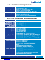
4.6. Q-Series Video Module Audio Specifications 23
4.7. Q-Series Video Modules Technical Specifications 23
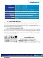
4.8. Status Indicator LEDs 24
4.8.1. Scaler Receiver Status LEDs 24
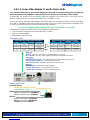
4.8.2. Q-Series Video Modules Tx and Rx Status LEDs 25
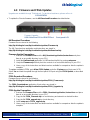
4.9. Firmware and FPGA Updates 26
5. REGULATORY & SAFETY COMPLIANCE 27
5.1 Safety Requirements 27
Symbols Found on the Product 27
Regulatory Compliance 27
North America 27
Australia & New Zealand 27
European Union 27
Standards with which Our Products Comply 27
5.2 Supplementary Information 28
Product Serial Number 28
Connection to the Product 28
6. HOW TO CONTACT US 28
6.1 Customer Support 28
Website, Email, Telephone, Fax 29
6.2 Product Support 30
6.2.1 Warranty 30
6.2.2 Return Authorization 30
Our Addresses 30
APPENDIX A: Quick Start Guides 31
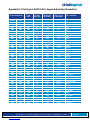
APPENDIX B: VQM-10 AV+ Supported Analog Resolutions 35
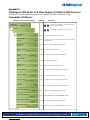
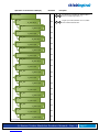
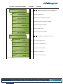
APPENDIX C: VQM-10 AV+ LCD Menu Options (Q-2300 & Q-4300 Chassis) 36
APPENDIX D: VQM-3 Scaler Menu Options 44
APPENDIX E: RJ45 to DB9 Adapter Pin-outs 51
APPENDIX F: EDID and DDC for Standard and HDCP Modules 52

®
Q - S e r i e s V i d e o M o d u l e s P r o d u c t M a n u a l , R e v . I
Page 4
PREFACE
About Thinklogical
Thinklogical, LLC®
100 Washington St.
Milford, CT 06460
2014
2013
We, the Thinklogical team, are committed to understanding and
exceeding our customers’ requirements, the first time and every time.
Thinklogical is the leading manufacturer and provider of fiber optic KVM, video, audio, and
peripheral extension and switching solutions used in video-rich, big-data computing
environments.
Thinklogical offers the only fiber-optic KVM matrix switches in the world that
are accredited to the Common Criteria EAL4, TEMPEST Level B, and NATO
NIAPC Evaluation Scheme: GREEN information assurance standards.
Governments, entertainment, scientific and industrial customers worldwide rely on
Thinklogical’s products and solutions for security, high performance, continuous operation
and ease of integration. Thinklogical products are designed and manufactured in the USA
and are certified to the ISO 9001-2008 standard.
Thinklogical is headquartered in Milford, Connecticut and is privately held by Riverside
Partners, LLC, Boston, MA (http://www.riversidepartners.com). For more information about
Thinklogical products and services, please visit www.thinklogical.com.
Follow Thinklogical on LinkedIn at http://www.linkedin.com/company/thinklogical and on
Facebook at http://www.facebook.com/ThinklogicalUSA

®
Q - S e r i e s V i d e o M o d u l e s P r o d u c t M a n u a l , R e v . I
Page 5
Note and Warning Symbols
Throughout this manual you will notice certain symbols that bring your attention to important information.
These are Notes and Warnings. Examples are shown below.
Note: Important Notes appear in blue text preceded by a yellow exclamation point
symbol, as shown here.
A note is meant to call the reader’s attention to helpful information at a point in the text that is relevant to
the subject being discussed.
Warning! All Warnings appear in red text, followed by blue text, and preceded by a
red stop sign, as shown here.
A warning is meant to call the reader’s attention to critical information at a point in the text that is relevant
to the subject being discussed.
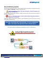
BEFORE STARTING ANY PROCEDURE, IT IS RECOMMENDED
THAT YOU READ THE INSTRUCTIONS THOROUGHLY!
All Q-Series modules are designed and identified as Class 1 LASER products
.
CLASS 1 LASERS do not require any special
precautions under conditions of normal use.
SFP
Modules
Fiber-Optic
Cables
Class 1 Lasers

®
Q - S e r i e s V i d e o M o d u l e s P r o d u c t M a n u a l , R e v . I
Page 6
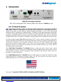
1. Introduction
VQM DVI Transmitter with Audio
H: 1.592” (4.40cm) x D: 6.366” (45.8cm) x W: 7.406” (44.5cm), 10 Watts per unit
1.1. Product Overview
MRTS Technology 6.25 Gbps. allows for Full Frame Rate Transmission of uncompressed DVI or
RGB video. Powered by Thinklogical’s® cutting edge, patent-pending MRTS (Multi Rate Transmission
System) Technology, our video extension systems transport every frame of a DVI or RGB video stream
seamlessly with no compression or dropped frames. In addition, all high speed peripherals function with
no latency. Incorporating standard SFP+ transceivers, the system uses fiber optic cables to
permit the
placement of a digital monitor or projector up to 1000 meters (3280 feet) away from the controlling
computer without loss of resolution. Installation is plug-and-play and no adjustments are necessary.
All Video modules support
D
ata
D
isplay
C
hannel (DDC)*, with a variety of modes to meet each
unique requirement. All models are connected by fiber optic cable(s), to provide communications to
and from the transmitter. The transmitter modules connect to a CPU with supplied video cables
(and audio & serial or network cables in AV+, AN+, AH and NH models). The receiver modules
provide an interface to the monitor(s) (and audio & serial or network devices in AV+, AN+, AH, NH
and video format scaler models).
Each
VQM Video Transmitter
(TX)
Module
features a video input and, in many cases, a local
video output which can be used for DDC modification and for displaying video at the source. The TX
also has fiber connectors used for transferring video and data to the Receiver. Status LEDS are
provided for system information.
Each
VQM Video Receiver
(RX)
Module
features 2 video outputs. On single DVI models, the video
output labeled DDC is always the primary output. The RX also has fiber connectors used for
transferring data to the TX and receiving video and data.
MADE IN USA
*See page 52: Appendix F: EDID and DDC for Standard and HDCP Modules

®
Q - S e r i e s V i d e o M o d u l e s P r o d u c t M a n u a l , R e v . I
Page 7
2. System Features
2.1 General System Features
The Q-Series’ hot-swappable interface modules allow any Q-Series Chassis to be used in a variety of
applications. Both transmitter and receiver modules can be installed together in one chassis. (A Q-4300
Chassis can hold up to four modules and a Q-2300 Chassis can hold up to two modules). Video Modules
are available to support single-link or dual-Link video display connections along with full duplex stereo
audio, stereo 3D emitter and serial RS-232 or network. A line of HDCP Compliant Velocity Q-Series
modules is also available (see pg. 17).
Installation possibilities are expanded with built-in support for either multi-mode or single mode fiber,
making this a convenient and cost effective solution to combat the restrictions involved with the
distribution of uncompressed broadcast quality video signals over long distances. Each module is hot
swappable and, in addition, the standard SFP+ optics (with LC connectors) are hot swappable/hot
pluggable. Every module is fully compatible with all of Thinklogical’s VXRouter line of products.
2.2 The Q-Series Chassis Line
Each Q-Series chassis allows users to locate DVI, RGB/DVI and SDI monitors (via fiber) from just a few
meters away to up to 40 kilometers away from the controlling computer, securely and without the loss of
resolution.
The Q-4300 is a rack space-saving, high reliability solution that provides a rack mount for up to 4
modules of DVI, RGB or SDI in a compact 1U chassis. Ready for the challenges of demanding
applications, both the Q-4300 and Q-2300 Chassis can combine any variety of DVI, RGB/DVI or SDI
modules in transmit/receive units for a space saving and cost effective solution.
The Q-1300 is a stand-alone chassis that will accommodate any one Q-Series module. All Q-Series
Chassis are powered by standard 100-240 VAC, 47-63 Hz.
Q-4300 Chassis: (VQS-004300) Supports any combination of up to four Q-Series modules.
Dual interface and current sharing power supplies. Desktop or 19" rack-mount.
Q-2300 Chassis: (VQS-002300) Supports up to two Q-Series modules. Desktop only.
Q-1300 Chassis: (VQS-001300) Supports one Q-Series module. Desktop only.

®
Q - S e r i e s V i d e o M o d u l e s P r o d u c t M a n u a l , R e v . I
Page 8
3. The Q-Series Video System
3.1. Types of Connections
All physical connections to the product use industry-standard connectors. Non-supplied cables
that may be needed are commercially available. All connections are found on the front panels of the
modules.
All models are connected via fiber optic cables (see paragraph 4.3. on page 19) to provide
communications to and from the transmitter. The transmitter connects to the CPU with supplied
Video
cables (and audio & serial or network cables in AV+, AN+, AH and NH models). The receiver
provides an interface to the monitor(s) and audio, serial or network devices in AV+, AN+, AH, NH
and video format scaler models. RJ45 to DB9 serial adapters are included with each transmitter and
receiver.
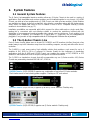
3.1.1 Fiber Optic Cable
Fiber optic cables
up to 1000 meters (3280 feet)
connect the Transmitters to the Receivers. Standard
multi-mode fiber optic cables must be 50 or 62.5 microns, terminated with LC type fiber optic connectors.
Multi-Mode Fiber-Optic Cable
T R T R
LC
TransmitReceive
LC
3" Multi-Mode:
Up to 50 meters with Type OM1
Up to 350 meters with Type OM2
Up to 750 meters with Type OM3
Up to 1000 meters with Type OM4
Single Mode:
Up to 80km with Type OS2 9/125 for all distances
Be careful not to kink or pinch the fiber optic cable as it is being installed and keep all bend
diameters to no less than 3 inches (76.2mm).
3.1.2 Transmitter
A transmitter unit connects to the computer and peripheral sources through standard copper cables. The
connector configurations of the Q-Series Transmitters can be viewed in detail on pages 12-17.
3.1.3 Receiver
A receiver module connects to a viewing device (monitor, projector) and USB and audio devices with
their own standard cables. The connector configurations of the Q-Series Module Receivers can be
viewed in detail on pages 12-17.

®
Q - S e r i e s V i d e o M o d u l e s P r o d u c t M a n u a l , R e v . I
Page 9
DVI IN Mod.1
DVI IN Mod.2
DVI IN Mod.3
DVI IN Mod.4
STEREO 3-D COAX IN
(Source 4)
DVI OUT Mod.1
DVI OUT Mod.2
DVI OUT Mod.3
DVI OUT Mod.4
STEREO 3-D OUT
(Source 4)
DVI OUT DDC
Mod. 4
DVI OUT DDC
Mod. 3
DVI OUT DDC
Mod. 2
DVI OUT DDC
Mod. 1
Local DVI OUT
Mod. 4
Local DVI OUT
Mod. 3
Local DVI OUT
Mod. 2
Local DVI OUT
Mod. 1
Q-4300 Transmitter Modules’ Local Displays
Control CPU
HDX576 Router
Source CPUs
Q-4300:
Transmitters
Q-4300:
Receivers
Q-4300 Receiver Modules’ DDC OUT Displays
1
2
3
4
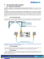
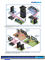
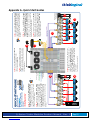
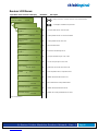
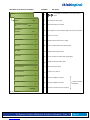
The VQM-3 Fiber Extension System- Up to 4 Single-Link DVI video signals can be extended in 1 RU
Q-4300:
Four VQM-3V Transmitter Modules
(VQM-00V003-LCTX)
DVI Fibers:
è L1: Video & Data Tx to Rx
ç L2: Data Rx to Tx
Source CPUs 1 & 2,
3V Mod. 4
Source CPUs 1 & 2,
3V Mod. 3
Source CPUs 1 & 2,
3V Mod. 2
Source CPUs 1 & 2,
3V Mod. 1
Q-4300:
Four VQM-3V Receiver Modules
(VQM-00V003-LCRX)
DVI OUT
Mod. 4-1
DVI OUT
Mod. 3-1
DVI OUT
Mod. 2-1
DVI OUT
Mod. 1-1
DVI OUT
Mod. 4-2
DVI OUT
Mod. 3-2
DVI OUT
Mod. 2-2
DVI OUT
Mod. 1-2
DVI IN Mod.1
DVI IN Mod.2
DVI IN Mod.3
DVI IN Mod.4
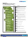
The VQM-3V Fiber Extension System- Up to 8 Independent Single-Link DVI video signals can be extended
in 1 RU

®
Q - S e r i e s V i d e o M o d u l e s P r o d u c t M a n u a l , R e v . I
Page 10
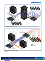
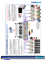
DVI Mod.1
DVI Mod.2
DVI Mod.3
DVI Mod.4
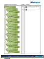
Q-4300:
4 VQM-3R Redundant Transmitter
Modules
(VQM-00R003-LCTX)
Fiber Optic Cables:
è L1/L1': Video & Data Tx to Rx/ Video & DataTx to Rx'
ç L2/L2': Data Rx to Tx/Data Rx to Tx’
Source CPU Mod. 4
Source CPU Mod. 3
Source CPU Mod. 2
Source CPU Mod. 1
Q-4300:
4 VQM-3R Redundant Receiver
Modules
(VQM-00R003-LCRX)
DVI OUT
Mod. 4
DVI OUT
Mod. 3
DVI OUT
Mod. 2
DVI OUT
Mod. 1
DVI OUT
DDC
Mod. 4
DVI OUT
DDC
Mod. 3
DVI OUT
DDC
Mod. 2
DVI OUT
DDC
Mod. 1
Local DVI
OUT Mod. 4Local DVI
OUT Mod. 3
Fiber Optic Cables
Rx
Local DVI
OUT Mod. 1
Local DVI
OUT Mod. 2
Tx
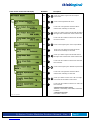
The VQM-3R Fiber Extension System- Up to 4 Single-Link DVI video signals can be extended in 1 RU with
4 Redundant Fiber Paths
DVI IN Mod.1
DVI IN Mod.2
DVI IN Mod.3
DVI IN Mod.4
STEREO 3-D COAX IN
(Source 4)
DVI OUT Mod.1
DVI OUT Mod.2
DVI OUT Mod.3
DVI OUT Mod.4
STEREO 3-D OUT
(Source 4)
DVI OUT DDC
Mod. 4
DVI OUT DDC
Mod. 3
DVI OUT DDC
Mod. 2
DVI OUT DDC
Mod. 1
Local DVI OUT
Mod. 4
Local DVI OUT
Mod. 3
Local DVI OUT
Mod. 2
Local DVI OUT
Mod. 1
Q-4300 Transmitter Modules’ Local Displays
Control CPU
VX320 Router
Source CPUs
Q-4300:
Transmitters
Q-4300:
Receivers
Q-4300 Receiver Modules’ DDC OUT Displays
1
2
3
4
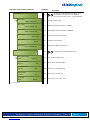
Dual-Link DVI Fibers:
è L1: Data Tx to Rx & Video Primary
ç L2: Data Rx to Tx
è L3: Video Secondary
The VQM-6 Fiber Extension System- Up to 4 Single-Link DVI video signals can be extended in 1 RU

®
Q - S e r i e s V i d e o M o d u l e s P r o d u c t M a n u a l , R e v . I
Page 11
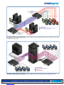
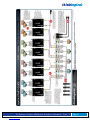
Stereo 3-D Coax IN
Fiber-Optic Cables
Control CPU
VX320 Router
Q-4300 (2) Q-4300 (1)
Q-4300 (1) RX
Module’s Destinations
Local DVI OUT
Q-4300 (2) TX
DVI OUT DDC
Q-4300 (1) RX
Source CPU 1
to Q-4300 (1)
TX Module
DVI OUT DDC
Q-4300 (2) RX
DVI OUT
Q-4300 (2) RX
Source CPU 2
to Q-4300 (2)
TX Module
Stereo 3-D OUT
Q-4300 (2) RX
Local DVI OUT
Q-4300 TX (1)
Active
Network
Active
Network
Vel-
3AN+ RX
Module
Vel-
3AN+ TX
Module
Network
Device
Network
Device
Data
Video
Stereo 3-D Coax IN
Data
Video
DVI OUT
Q-4300 (1) RX
Vel-
3AN+ TX
Module
Vel-
3AN+ RX
Module
Fiber-Optic Cables
Q-4300 (2) RX
Module’s Destinations
Stereo 3-D OUT
Q-4300 (1) RX
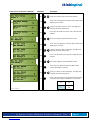
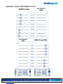
The VQM-3AN+ Fiber Extension System- Up to 2 Single-Link DVI video signals plus a network connection
can be extended in 1 RU
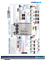
Local DVI OUT
VQM-6 A/V+
Module 1
Source to
VQM-6 A/V+
Tx Module 1
Q-4300 Tx
Destination of
VQM-6 A/V+ Tx
Module 1
Fiber Optic Cables
DDC
Velocitydvi-6 A/V+ Rx 1
Local DVI OUT
VQM-6 A/V+
Module 2
Source to
VQM-6 A/V+
Tx Module 2
Destination of
VQM-6 A/V+ Tx
Module 2
DDC
Velocitydvi-6 A/V+ Rx 2
Fiber Optic Cables
Fiber-Optic Cables:
L1: Data Tx to Rx & Video 1
L2: Data Rx to Tx
L3: Video 2
The VQM-6AV+ to Vel-6AV+ Fiber Extension System Configuration- Up to 2 Single-Link DVI video
signals plus audio can be extended in 1 RU

®
Q - S e r i e s V i d e o M o d u l e s P r o d u c t M a n u a l , R e v . I
Page 12
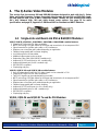
4. The Q-Series Video Modules
This section lists the various DVI and RGB/DVI Modules designed to work with the Q- Series
Video and Audio Extension System. Supported video formats include DVI and RGB/DVI single-
link and dual-link and a line of HDCP compliant models. Models are also available with Audio
(AV+, AH), Network (AN+, NH) and video format scaler options. See page 23 for audio
specifications and page 52, Appendix F: EDID and DDC for Standard and HDCP Modules.
4.1 Single-Link and Dual-Link DVI & RGB/DVI Modules:
VQM-3, VQM-3R, VQM-3AV+, VQM-3RAV+, VQM-3AN+ & VQM-3RAN+ module features:
Supports all Single-Link DVI video resolutions
MRTS technology 6.25Gbps allows for full frame rate transmission of uncompressed DVI
Signal transmission via fiber optic cable; no RF interference
Requires one or two fiber optic cables depending on application
Flawless image quality with no frame dropping
Local video port on the transmitter
Additional video output on the receiver
Redundant Fiber Path (VQM-00R003 models only)
Audio and RS-232 serial port (on AV + models only)
Audio and Network port (on AN + models only)
DDC2B/EDID compliant
Simple plug and play
VQM-3V, VQM-3V AV+ and VQM-3V AN+ module features:
Up to 8 independent Single-Link DVI video signals can be extended in 1 RU
Supports all Single-Link DVI video resolutions
Two DVI-D signals can be extended with one module
MRTS technology 6.25Gbps allows for full frame rate transmission of uncompressed DVI
Signal transmission via fiber optic cable; no RF interference
Requires two or four fiber optic cables depending on application
Flawless image quality with no frame dropping
Audio and RS-232 serial ports (on AV + models only)
Audio and Network ports (on AN + models only)
DDC2B/EDID compliant
Simple plug and play
VQM-3, VQM-3V and VQM-3R Tx and Rx DVI Modules:
VQM-3, TX Single Video VQM-3, RX Single Video

®
Q - S e r i e s V i d e o M o d u l e s P r o d u c t M a n u a l , R e v . I
Page 13
VQM-3V, TX Dual Video VQM-3V, RX Dual Video
VQM-3R, TX Redundant Video VQM-3R, RX Redundant Video
VQM-3 AV+ and VQM-3 AN+ Tx and Rx DVI Family of Modules:
VQM-3 AV+, TX Single Video, Audio, Serial
VQM-3 AV+, RX Single Video, Audio, Serial
VQM-3V AV+, TX Dual Video, Audio, Serial

®
Q - S e r i e s V i d e o M o d u l e s P r o d u c t M a n u a l , R e v . I
Page 14
VQM-3V AV+, RX Dual Video, Audio, Serial
VQM-3R AV+, TX Redundant Video, Audio, Serial
VQM-3R AV+, RX Redundant Video, Audio, Serial
VQM-3 AN+, TX Single Video, Audio, Network
VQM-3 AN+, RX Single Video, Audio, Network

®
Q - S e r i e s V i d e o M o d u l e s P r o d u c t M a n u a l , R e v . I
Page 15
VQM-3V AN+, TX Dual Video, Audio, Network
VQM-3V AN+, RX Dual Video, Audio, Network
VQM-3R AN+, TX Redundant Video, Audio, Network
VQM-3R AN+, RX Redundant Video, Audio, Network
VQM-6, VQM-6 AV+ and VQM-6 AN+ Tx and Rx DVI Modules:
(Pictured on page 16)
VQM-6, VQM-6 AV+ and VQM-6 AN+ module features:
Supports all Single-Link and Dual-Link DVI video resolutions
MRTS technology 6.25Gbps allows for full frame rate transmission of uncompressed DVI
Signal transmission via fiber optic cable; no RF interference
Requires two or three fiber optic cables depending on application
Flawless image quality with no frame dropping
Local video port on the transmitter
Additional video output on the receiver
Audio and RS-232 serial ports (on AV+ models only)
Audio and Network ports (on AN+ models only)
DDC2B/EDID compliant
Simple plug and play

®
Q - S e r i e s V i d e o M o d u l e s P r o d u c t M a n u a l , R e v . I
Page 16
VQM-6, TX Dual-Link Video VQM-6, RX Dual-Link Video
VQM-6 AV+, TX Dual-Link Video, Audio, Serial
VQM-6 AV+, RX Dual-Link Video, Audio, Serial
VQM-6 AN+, TX Dual-Link Video, Audio, Network
VQM-6 AN+, RX Dual-Link Video, Audio, Network

®
Q - S e r i e s V i d e o M o d u l e s P r o d u c t M a n u a l , R e v . I
Page 17
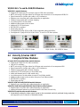
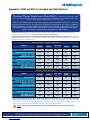
VQM-10 AV+ Tx and Rx RGB/DVI Modules:
VQM-10AV+ module features:
Supports all Single-Link DVI and most common RGB video resolutions
MRTS technology 6.25Gbps allows for full frame rate transmission of uncompressed RGB/DVI
Signal transmission via fiber optic cable; no RF interference
Requires one or two fiber optic cables depending on application
Flawless image quality with no frame dropping
Local video port on the transmitter
Additional video output on the receiver
Audio and RS-232 serial ports
DDC2B/EDID compliant
Simple plug and play
See Appendix B (page 35) for VQM-10 AV+ supported analog resolutions
See Appendix C (page 36-43) for VQM-10 AV+ Tx and Rx LCD Menu options
VQM-10 AV+, TX RGB/DVI Video VQM-10 AV+, RX RGB/DVI Video
4.2 Velocity Q-Series HDCP
Compliant Video Modules
Q-Series HDCP Compliant Video module features:
Supports all Single-Link DVI video resolutions
Fully HDCP compliant
MRTS technology 6.25Gbps allows for full frame rate transmission of uncompressed DVI
Signal transmission via fiber optic cable; no RF interference
Flawless image quality with no frame dropping
Audio and RS-232 serial ports (on AH models only)
Audio and Network ports (on NH models only)
Local video port on the transmitter (except on Dual Video models)
Additional video output on the receiver (except on Dual Video models)
DDC2B/EDID compliant
Simple plug and play
VQM-3H, VQM-3AH and VQM-3NH module features:
Requires one or two fiber optic cables depending on application
VQM-3HV, VQM-3AHV and VQM-3NHV (Dual Video) module features:
Requires two to four fiber optic cables depending on application
Audio and Network features are functional with the first video channel only
VQM-3AVS Scaler Receiver module features:
Automatically scales the video output format to the connected monitor’s preferred timing resolution
and supports up to 8 channels of embedded audio.

®
Q - S e r i e s V i d e o M o d u l e s P r o d u c t M a n u a l , R e v . I
Page 18
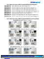
4.2.1. Velocity Q-Series HDCP Compliant Module Part Numbers:
VQM-0H0003-LCRX VQM-3, Single Link DVI, DDC, HDCP Compliant, RX, LC
VQM-0H0003-LCTX VQM-3, Single Link DVI, DDC, HDCP Compliant, TX, LC
VQM-AH0003-LCRX VQM-3 AV+, Single Link DVI, DDC, Audio, Serial, HDCP Compliant, RX, LC
VQM-AH0003-LCTX VQM-3 AV+, Single Link DVI, DDC, Audio, Serial, HDCP Compliant, TX, LC
VQM-NH0003-LCRX VQM-3 AV+, Single Link DVI, DDC, Audio, Network, HDCP Compliant, RX, LC
VQM-NH0003-LCTX VQM-3 AV+, Single Link DVI, DDC, Audio, Network, HDCP Compliant, TX, LC
VQM-NHV003-LCRX VQM-3 AVV+, Dual Single Link DVI, DDC, Audio, Network, HDCP Compliant, RX, LC
VQM-NHV003-LCTX VQM-3 AVV+, Dual Single Link DVI, DDC, Audio, Network, HDCP Compliant, TX, LC
VQM-0HV003-LCRX VQM-3V, Dual Single Link DVI, DDC, HDCP Compliant, RX, LC
VQM-0HV003-LCTX VQM-3V, Dual Single Link DVI, DDC, HDCP Compliant, TX, LC
VQM-AHV003-LCRX VQM-3 AVV+, Dual Single Link DVI, DDC, Audio, Serial, HDCP Compliant, RX, LC
VQM-AHV003-LCTX VQM-3 AVV+, Dual Single Link DVI, DDC, Audio, Serial, HDCP Compliant, TX, LC
VQM-AV00S3-LCRX VQM-3 AV+, Single Link DVI, DDC, Audio, Serial, HDCP Compliant, Scaler RX, LC
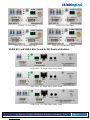
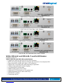
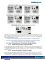
4.2.2. Velocity Q-Series HDCP Compliant Module Front Panel Views
VQM-AH0003-LCTX/RX (A=Audio, H=HDCP capability)
VQM-NH0003-LCTX/RX (N=Network, H=HDCP capability)
VQM-0H0003-LCTX/RX (H=HDCP capability)
VQM-0HV003-LCTX/RX (V=Dual Video, H=HDCP capability)

®
Q - S e r i e s V i d e o M o d u l e s P r o d u c t M a n u a l , R e v . I
Page 19
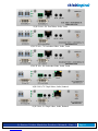
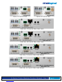
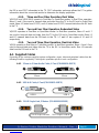
VQM-AHV003-LCTX/RX (A=Audio, H=HDCP capability, V=Dual Video)
VQM-NHV003-LCTX/RX (N=Network, H=HDCP capability, V=Dual Video)
DVI to Display
L2 L1
MIC IN LINE OUT
VQM-AV00S3-LCRX SERIAL
HDCP
HDMI/DVI
LOS/HP
CTRL
VQM-AV00S3-LCRX (A=Audio, V=Video, S=Scaler)
Thinklogical’s Q-Series Scaler Receiver is HDCP compliant and automatically scales the video output format to the
connected monitor’s preferred timing resolution while supporting up to 8 channels of embedded audio. As with all
HDCP compliant models, the Scaler Receiver is available with LC-Type fiber connectors only. (See Appendix D:
VQM-3 Scaler Menu Options on page 44.)
All physical connections to the Q-Series Video Modules use industry-standard
connectors. Non-supplied cables that may be needed are commercially available.
All connections are found on each module’s front panel.
4.3 Fiber Connections to the Q-Series Video Modules
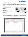
4.3.1. Single Fiber Operation, Single-Link Video
The unit will operate with a single fiber from the TX to the RX. In this mode of operation the TX
can transmit video and data to the RX over fiber L1. The RX cannot send any information to the
TX. Also, DDC information can only be gathered from the TX local port or the Thinklogical
default EDID table.
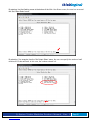
4.3.2. Dual Fiber Operation, Single-Link Video
In this mode video information is transmitted from the TX to the RX over fiber L1. Fiber L2 is
used as a data return path from the RX to the TX. Providing a back channel from the RX to the
TX allows the RX to modify DDC configuration via the Front Panel LCD and buttons and allows

®
Q - S e r i e s V i d e o M o d u l e s P r o d u c t M a n u a l , R e v . I
Page 20
the RX to send DDC information to the TX. DDC information exchange allows the PC to gather
information about the connected monitor to determine the display properties.
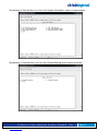
4.3.3. Three and Four Fiber Operation, Dual Video
VQM-3HV and VQM-3AHV operate in Dual-fiber or Quad-fiber modes. In Dual-Fiber operation,
fibers L1 and L3 are used to transmit data and video from the TX to the RX and in Quad-Fiber
mode, fibers L2 (video head 1 DDC) and L4 (video head 2 DDC) transmit data from the RX back
to the TX. 4.3.4. Two and Four Fiber Operation, Redundant Video
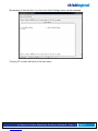
VQM-3R operates in Dual-fiber or Quad-fiber modes. In dual-fiber operation, fibers L1 and L1’
are used to transmit data and video from the TX to the RX and in Quad-fiber mode, fibers L2
and L2’ transmit data from the RX back to the TX. L1’ and L2’ are copies of L1 and L2
respectively.
4.3.5. Two and Three Fiber Operation, Dual-Link Video
VQM-6 operates in Dual-fiber or Triple-fiber modes. In dual-fiber operation, fibers L1 and L3 are
used to transmit data and video from the TX to the RX. In three-fiber mode, fiber L2 transmits
data from the RX back to the TX.
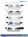
4.4. Supplied Cables
Depending on the customer-specified system configuration, power, video and peripheral cables from the
following list will be supplied by Thinklogical in quantities specific to each configuration:
4.4.1 3.5mm to 3.5mm Audio Cable, 6 Feet (CBL000016-006FR)
3.5mm 3.5mm
4.4.2 USB A-B Cable, 6 Feet (CBL000015-006FR)
USB B USB A
4.4.3. DVI-D Single-Link, 2 Meters (CBL000009-002MR)
DVI-D Single-Link Male DVI-D Single-Link Male
La pagina si sta caricando...
La pagina si sta caricando...
La pagina si sta caricando...
La pagina si sta caricando...
La pagina si sta caricando...
La pagina si sta caricando...
La pagina si sta caricando...
La pagina si sta caricando...
La pagina si sta caricando...
La pagina si sta caricando...
La pagina si sta caricando...
La pagina si sta caricando...
La pagina si sta caricando...
La pagina si sta caricando...
La pagina si sta caricando...
La pagina si sta caricando...
La pagina si sta caricando...
La pagina si sta caricando...
La pagina si sta caricando...
La pagina si sta caricando...
La pagina si sta caricando...
La pagina si sta caricando...
La pagina si sta caricando...
La pagina si sta caricando...
La pagina si sta caricando...
La pagina si sta caricando...
La pagina si sta caricando...
La pagina si sta caricando...
La pagina si sta caricando...
La pagina si sta caricando...
La pagina si sta caricando...
La pagina si sta caricando...
La pagina si sta caricando...
La pagina si sta caricando...
-
 1
1
-
 2
2
-
 3
3
-
 4
4
-
 5
5
-
 6
6
-
 7
7
-
 8
8
-
 9
9
-
 10
10
-
 11
11
-
 12
12
-
 13
13
-
 14
14
-
 15
15
-
 16
16
-
 17
17
-
 18
18
-
 19
19
-
 20
20
-
 21
21
-
 22
22
-
 23
23
-
 24
24
-
 25
25
-
 26
26
-
 27
27
-
 28
28
-
 29
29
-
 30
30
-
 31
31
-
 32
32
-
 33
33
-
 34
34
-
 35
35
-
 36
36
-
 37
37
-
 38
38
-
 39
39
-
 40
40
-
 41
41
-
 42
42
-
 43
43
-
 44
44
-
 45
45
-
 46
46
-
 47
47
-
 48
48
-
 49
49
-
 50
50
-
 51
51
-
 52
52
-
 53
53
-
 54
54


Thinklogical Q-4300 Manuale utente
- Tipo
- Manuale utente
in altre lingue
- English: Thinklogical Q-4300 User manual
Altri documenti
-
Zebra MC55 Guida utente
-
Zebra MC75A Guida utente
-
-
Planar MX55-L Guida Rapida
-
Cisco 7606 Guida d'installazione
-
AJA FS1-X Installation and Operation Guide
-
Juniper QFX5220 Manuale utente
-
-
-
AJA OG-X-FR Manuale utente