
INSTRUCTION FOR USE
BEDIENUNGSANLEITUNG
MODE D‘EMPLOI
INSTRUCCIONES DE USO
ISTRUZIONI D´USO
NÁVOD K POUŽITÍ
GCE VALVES
PRESSURE REGULATORS INTEGRATED
WITH CYLINDER VALVE
DRUCKREGLER MIT FLASCHENVENTILEN
EN
DE
MediVitop®
DETENDEURS INTEGRES
REGULADORES DE PRESIÓN INTEGRADOS
CON VÁLVULAS DE BOTELLA
FR
ES
RIDUTTORE DI PRESSIONE INTEGRATO CON VALVOLE
PER BOMBOLA
REDUKČNÍ VENTILY S INTEGROVANÝM
UZAVÍRACÍM VENTILEM PLYNOVÝCH LAHVÍ
IT
CS

2/59
EN
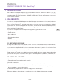
1. FOREWORD
The product complies with essential requirements of 93/42/EEC Medical Device Directive,
2010/35/EU Transportable Pressure Equipment Directive and CDG TPE (Amendment) & (EU
Exit) Regulations 2020.
The valve is designed according to EN ISO 10524-3 standard.
2. INTENDED USE
MediVitop® Combination Valves are designed to be fi tted to gas cylinders used for medical
gases. These combination valves together with a gas cylinder form gas packages used either
as gas supply point for medical devices (anaesthetic devices, ventilating devices, fl owmeters,
suction ejectors, incubators etc.) or for direct gas supply to a patient’s breathing mask, cannula
or humidifi er.
GCE Combination Valves are intended to be used with the following medical gases:
• Oxygen
• Nitrous oxide
• Air for breathing
• Helium
• Carbon dioxide
• Xenon
• Specifi ed mixtures of the gases listed
2.1. PATIENT PROFILE
Regulator valve get gas fl ow from 0 to 25 liter per minutes. Information about specifi cation fl ow
rate you can fi nd in the appendix No. 1 of instruction for use. Flow rate is listed in the Appendix
No. 1 of instruction of use in the table on the position C and this Appendix is supplied to every
product.
The saturation of gas must be estimated by doctor or anesteziologic nurse. They have nec-
essary education, where they must know health status of patient and get him important gas
support.
Health status - used, when the patient will be need to support of medical gases for supporting
breathing and decision about treatment is on the side doctor or health personal.
Health personal – nurse, rescuer, paramedic, keeper or person with medical education.
2.2. USER PROFILE
Use in a hospital or in an ambulance
• Education: personal with medical education
Use in home care
Treatment is description from a doctor or personal with medical education or who set this sup-
porting of breathing
• Knowledge: training from person with medical education ability to read, study and knowl-
edge of user manual
Training is provided according to local law in individuals countries.
Important:
The patient must be trained by doctor or person, who has education on the fi eld of safe life.
ENGLISH
INSTRUCTION FOR USE: MediVitop®

3/59
EN
3. OPERATIONAL, TRANSPORT AND STORAGE SAFETY
REQUIREMENTS
Keep the product and its associated equipment away from:
• Heat sources (fi re, cigarettes,...)
• Flammable materials
• Oil or grease (take a great care in the use of hand creams)
• Water
• Dust
The product and its associated equipment must be prevented from tipping over, turning over
or falling.
Always maintain oxygen cleanliness standards.
Only use the product and its associated equipment in well ventilated area.
Before the fi rst use the product shall be kept in its original package. If removed from service
(for transport, storage) GCE recommends using the original package (including inner packing
materials).
National laws, rules and regulations for medical gases, accident prevention and environmental
protection must be observed.
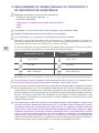
OPERATING CONDITIONS STORAGE AND TRANSPORT CONDITIONS
-20* / +65 °C -40 / +70 °C
10 / 100 % 10 / 100 %
600 / 1200 mbar 600 / 1200 mbar
*for inner tightness of the shut-off valve, during transport and storage of the combination valve
mounted on a cylinder, the valid lower temperature limit is -40°C.
In case of combination valve storage at temperature below -20°C do not use the combination
valve until its temperature reaches at least -20°C.
For the combination valves designed to be used with mixture of gases O2+N2O, the lowest
operating temperature is +5°C. In normal use of the combination valve, frosting can appear on
the combination valve surface, which is caused by the gas inside the combination valve when
high pressure in the combination valve cooling when high pressure gas is being reduced to
low pressure (Joule-Thomson e ect). Check that all patient associated equipment connected
to the combination valve is via a hose of at least 2 metres length.
O2+N2O mixtures are temperature sensitive. N2O begins to separate out from the mixture if
the temperature falls below about -6°C. A homogenous mixture is again obtained when the
temperature has raised above 10°C and the cylinder was agitated. Before use, to ensure it is
properly mixed, cylinders should be stored horizontally for 24 hours at a temperature above
10°C. If this is not practicable, before use the cylinders must be maintained at a temperature
above 10°C for at least 2 hours and then completely inverted three times or placed in warm
water at body temperature for 5 minutes and then completely inverted three times.

4/59
EN
4. PERSONNEL INSTRUCTIONS
The Medical Devices Directive 93/42/EEC states that product provider must ensure that all
personnel handling the product are provided with the operating instructions & performance
data.
Do not use the product without properly familiarization of the product and its safe operation
as defi ned in this Instruction for use. Ensure user is aware of particular information and knowl-
edge required for the gas in use.
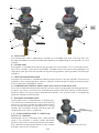
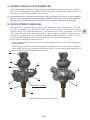
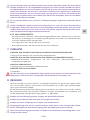
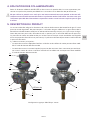
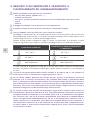
5. PRODUCT DESCRIPTION
Combination valve combines the function of shut-off valve of a high pressure gas cylinder and
pressure regulator for the use with medical gases. Gas from the cylinder is fi rst controlled by
the main shut-off valve and then passed through the pressure regulator and fi nally delivered to
the patient through the fl ow outlet or the pressure outlet. Outlet positive pressure is fi xed by the
manufacturer and each combination valve is provided with a low-pressure relief valve to protect
against undesirable exceeding of outlet pressure.
There are two basic alternatives:
• Valve outlet via calibrated nozzles, outlet fl ows can be changed by the control knob
• Valve outlet via quick-coupler (the outlet fl ow is a constant one) in combination with valve
outlet via calibrated nozzles where outlet fl ows can be changed by the control knob
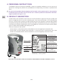
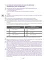
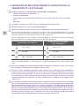
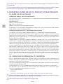
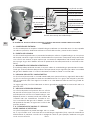
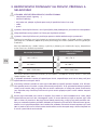
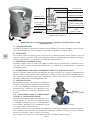
THE LAYOUT OF THE TEXT IS ONLY ILLUSTRATIVE, SOME VARIANTS MAY BE A DIFFERENT LAYOUT
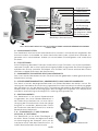
Serial number
Inlet connection
type
Reference
number
Inlet pressure
Total weight
allowance of the
package
Filling port type
Compliance with
2010/35/EU
Compliance with
93/42/EEC
MediVitop® marking detail
End of lifetime
Compliance with CDG
TPE (Amendment) &
(EU Exit) Regulations
2020
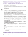
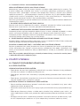
K

5/59
EN
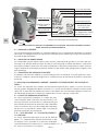
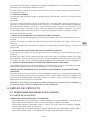
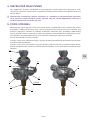
D
G
C
A
F
H
E
B
I
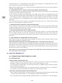
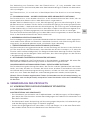
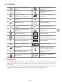
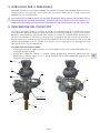
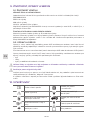
MARKING
DETAIL
J
A INLET STEM
The combination valve is fi tted to gas cylinder by a threaded inlet stem. The inlet stem can
be taper threaded or parallel threaded with diff erent size depending on the cylinder size and
material.
B FILLING PORT
A fi lling port is provided for fi lling the gas cylinder at a fi lling station, it has no function for pa-
tient use. It includes a non-return valve (NRV). The NRV means that special fi lling adaptors are
required to vent gas from the cylinder during the fi lling process (venting and/or vacuuming of
cylinders).
C INLET PRESSURE INDICATOR
Inlet pressure indicator is intended to indicate amount of gas in the gas cylinder. The pressure
indicator is of an active type which means it indicates amount of gas in the gas cylinder whether
the shut-off valve is opened or closed.
D COMBINATION CONTROL KNOB “SHUTOFF VALVE & FLOW SELECTOR“
The valve is fi tted with combination control knob for valve turning-on/off and setting of particu-
lar fl ows. The valve is turned on by anticlockwise rotation from OFF position to ON position.
Particular fl ows are set by further anticlockwise rotation. The shut-off valve is turned off by
clockwise rotation to OFF position.
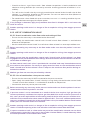
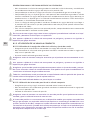
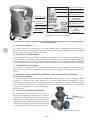
E RESIDUAL PRESSURE VALVE
Combination valve is equipped with a residual pres-
sure valve with function to retain a minimum positive
pressure in the gas cylinder to avoid contamination
of the cylinder content by atmospheric air. During
cylinder gas ventilation through the fi lling port the
residual pressure valve is by passed.
F, G FLOW CONTROL HEAD “F” AND FLOW
OUTLET “G” OPTION
Combination valve is delivered with a fl ow control
head “F”.This function is used to supply adjustable
gas fl ow rates (l/min) at atmospheric pressure direct-
ly to a patient through the fl ow outlet “G”, for instance
through a cannula or a facemask. Connecting the cannula

6/59
EN
The fl ow outlet “G“ is equipped with hose fi tting (hose nipple) or a threaded type (for acces-
sories to be connected via threaded connection).
Movement of the fl ow outlet ‘G’ is normal due to the method of fi xing in the main body. It doesn’t
indicate a faulty fl ow outlet.
H PRESSURE OUTLET QUICK COUPLER OR PURGE VALVE OPTION
The pressure outlet is the outlet direct from the low-pressure part of the valve and it is fi tted with
a specifi c quick connector or purge valve.
In the use of the valve with quick connector also called ”quick coupler“ (see appendix Nr 2) the
user can connect another piece of equipment to quick coupler with a gas specifi c male probe
– quick-coupler probe. Its disconnection means self-sealing of the quick connector. This outlet
is for supplying gas at a controlled pressure to power medical devices, for instance medical
ventilator.
The valve without the quick coupler is provided with purge valve that is used to vent residual
pressure in the low-pressure part of the valve.
I PRESSURE RELIEVE VALVE OF LOW PRESSURE PART
Pressure relieve valve secures the low pressure part of combination valve and connected medi-
cal devices against over-pressure. If the gas pressure is decreased enough after the pressure
relieve valve activation, it will closes itself.
J EXCESS FLOW DEVICE OR DIP TUBE OPTION
Excess fl ow device ensures safe ventilation of gas from gas cylinder in case the combination
valve is broken above inlet stem (e.g. cylinder fall). Dip tube does not have such function. Ex-
cess fl ow device and dip tube are to avoid contamination from cylinder entering the combina-
tion valve.
K BED HANGER OR HUMIDIFIER HOLDER OPTION
Bed hanger enables to hang medical gas package on hospital bed. Humidifi er holder enables
to connect humidifi er to the combi valve.
PRESSURE RELIEVE DEVICE OF HIGH PRESSURE PART BURSTING DISC OPTION
The high pressure relieve device is intended to protect the cylinder and high pressure part of
combination valve against damage caused by increased cylinder pressure. If the pressure re-
lieve device has been activated, it will not reseal and the combination valve must be taken out
of service for repair (see Chapter 9).
Note: Colour of the product (especially guard and combination control knob) does not have
to match the gas colour coding.
6. USE OF PRODUCT
6.1. OPERATIONS PERFORMED BY USER
6.1.1. BEFORE USE
VISUAL INSPECTION BEFORE USE:
• Check the combination valve for damage (incl. label and marking). If it shows signs of external
damages, remove the product from service and suitably identify its status.
• Visually check the combination valve for contamination. If needed, apply the cleaning proce-
dure according to chapter 8.
• Check that the cylinder gas pressure indicator indicates suffi cient pressure. If it indicates in
the red zone, return the cylinder with combination valve back for fi lling.
LEAKTIGHT AND FUNCTIONAL TEST BEFORE USE:
• Open slowly the combination shut-off valve by turning slowly the combination control knob
“shut-off valve & fl ow selector“ in anticlockwise direction to ON position.
• By listening check for leakage (leakage would be heard as characteristic hiss of fl owing gas).

7/59
EN
• Check that there is a gas fl ow at each “fl ow selector“set position in both anticlockwise and
clockwise turning direction (for instance by sound or checking presence of bubbles in a hu-
midifi er)..
• Turn off at the shut-off valve by turning the combination control knob“shut-off valve & fl ow
selector“ in a clockwise direction to OFF position. Do not use excessive force (Maximum
recommended closing torque is 3 Nm).
• For combination valves fi tted with pressure outlet, ensure it is in working condition by con-
necting and disconnecting quick-coupler probe.
If any leakage is detected, apply the procedure described in Chapter 6.2.3. and return the
valve for service.
Sudden opening could result in a danger of fi re or explosion arising from oxygen pressure
shocks.
6.1.2. USE OF COMBINATION VALVE
6.1.2.1. Use of combination valve fl ow outlet and setting of fl ow
• Ensure that the accessory is connected to the fl ow outlet.
• Open slowly the combination control knob “shut-off valve & fl ow selector“ in anticlockwise
direction to ON position.
• Set the combination control knob "shut-off valve & fl ow selector" on one required fl ow rate.
Before connecting any accessory to the fl ow outlet make sure that the patient is not con-
nected
Sudden opening could result in a danger of fi re or explosion arising from oxygen pressure
shocks.
Always ensure that the combination control knob "shut-o valve & fl ow selector" has been
engaged and not placed between two settings otherwise the fl ow control head will not deliver
correct fl ow of medical gas.
On fl ow control head, each valve is provided with so-called "end stop" located downstream
the maximum fl ow position. Do not try to apply excessive force on the combination control
knob "shut-o valve & fl ow selector" when it stops on the maximum fl ow position during an-
ticlockwise rotation.
Medical gas fl ow rate must be prescribed by a doctor.
6.1.2.2. Use of combination valve pressure outlet
• Ensure that the accessory IS NOT connected to the pressure outlet.
• Open slowly the combination shut-off valve by turning slowly the combination control knob
“shut-off valve & fl ow selector“ in anticlockwise direction to ON position.
• Connect the accessory to the pressure outlet.
Before connecting any accessory to the pressure outlet make sure that the patient is not con-
nected and the accessory outlet is secured.
If pressure outlet is to be connected to a medical device that requires high gas fl ow (for
instance pulmonary ventilator that requires gas fl ow 100 l/min at the minimum pressure 2.8
bar), com- pare the required fl ow of connecting medical device with pressure and fl ow char-
acteristics of the combination valve stated in appendix Nr. 1. To assure su cient performance
(pressure and fl ow characteristics of the combination valve ) the medical device should not be
used if pressure indicator enters the red zone.
Sudden opening could result in a danger of fi re or explosion arising from oxygen pressure
shocks. Insu cient opening of the shut-o valve could reduce actual fl ow delivered.
If a pressure outlet as well as a fl ow outlet are part of the combination valve do not use them
simultaneously, especially if pressure in the cylinder is below 50 bar, in could adversely a ect
the outlet parameters of the combination valve .

8/59
EN
6.1.3. AFTER USE
• Turn off at the shut-off valve by turning the combination control knob“ shut-off valve & fl ow
selector“ in a clockwise direction to OFF position. Do not use excessive force (Maximum
recommended closing torque is 3 Nm).
• Vent pressure from the connected devices.
• Disconnect all connected devices from user outlets.
• Place the output protective caps back (if present). Ensure that the caps are clean before
replacing the caps.
7. ACCESSORIES
ACCESSORIES CONNECTABLE TO FLOW OUTLET:
• hose connected with mask, cannula or humidifi er.
ACCESSORIES CONNECTABLE TO PRESSURE OUTLET:
• low pressure hose (working pressure >10 bar), fl owmeters, Venturi suction ejectors, lung ven-
tilators.
OTHER USER ACCESSORIES:
• bed hanger, humidifi er holder.
ACCESSORIES FOR FILLING STATIONS:
• fi lling adaptor.
Before connecting any accessory or medical device to the combination valve, always check
that they are fully compatible with connection features & performances of the product.
8. CLEANING
Remove dirt with a soft cloth damped in oil free soap water & rinsed with clean water. Clean-
ing of external surface can be carried out with an alcohol-based solution (with damped wipes).
If other cleaning solutions are used, check that they are not abrasive and they are compatible
with the product materials (including labels) and gas (convenient cleaning solution - i.e. Meli-
septol)
Do not use cleaning solutions containing ammonia!
Do not expose to water or any other liquid.
Do not expose to high temperature (such as autoclave).
To apply the cleaning solution do not spray it as the spray may enter into the inner parts of
combination valve and cause contamination or damage.
Do not use pressure wash as it could damage or contaminate the combination valve .
If the inner parts of the combination valve have been contaminated do not continue to use the
combination valve under any circumstances. It must be withdrawn from service.
9. SERVICE, PRODUCT LIFE TIME AND MAINTENANCE
9.1. PRODUCT LIFE TIME
Serial number and manufacture date
An eleven-fi gure serial number stamped on valve body consists of the data as follows:
YYYYMMXXXXX
YYYY: year of manufacture
MM: month of manufacture
XXXXX: sequence number of product

9/59
EN
For example: Serial number 20151001521 indicates the valve manufactured in 2015, in October,
with sequence number 1521.
Product life time and waste management
Maximum operating life time of this product is 15 years from date of manufacture.
At the end of the product’s life time, the product must be withdrawn from service. The provider
of the device shall prevent the reuse of the product and handle the product in compliance with
“Directive of European Parliament and Council 2008/98/EC on waste“.
In accordance to Article 33 of REACH GCE, s.r.o. as responsible manufacturer shall inform all
customers if materials containing 0.1% or more of substances included in the list of Substance
of Very High Concern (SVHC). The most commonly used brass alloys used for bodies and other
brass components contain 2-3% of lead (Pb), EC no. 231-468-6, CAS no. 7439-92-1. The lead
will not be released to the gas or surrounding environment during normal use. After end of
life the product shall be scrapped by an authorized metal recycler to ensure effi cient material
handling with minimal impact to environment and health. To date we have no information that
indicates that other materials containing SVHC of concentrations exceeding 0.1% are included
in any GCE product.
9.2. REPAIR AND SERVICE OPERATIONS
Repairs and service can be only done by a GCE certifi ed person who also holds all necessary
certifi cates in compliance with national standards for mounting and repair of dedicated gas
devices.
For information about a service in your area please contact GCE or distributor of GCE product.
Usually the combination valves can be repaired while fi tted on the cylinder.
Repair that do not need to be done by certifi ed personnel include exchange of the below
mentioned components:
• guard,
• labels,
• protective covers and separable hose adaptors.
All labels on the equipment must be kept in good, legible condition by the provider and the
user during the entire product life time.
Use only genuine GCE components.
Any product sent back to GCE (or GCE authorised centre) for repair or maintenance shall be
properly packaged to prevent contamination or damage during storage, transportation and
handling.
For product to be repaired, the fault short description or some reference to a claim nr. should
be indicated.
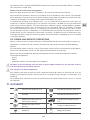
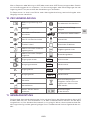
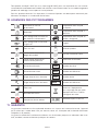
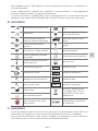
10. GLOSSARY
Consult instruction for use Suitable for Hospital care use
Caution! Suitable for Home care use
Keep away from heat and
fl ammable materials.
Suitable for Emergency care
use
Keep away from oil and
grease! Fragile, handle with care
Keep dry! Weight of product

10/59
EN
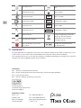
Humidity limit Atmospheric pressure limita-
tion
Temperature limit Use by date
Inlet parameter SN Serial number
Outlet parameter REF Catalogue number
P1Inlet pressure LOT Batch code
P2Outlet pressure REF 1 Catalogue number
Manufacturer Take the equipment back for
recycling. Do not dispose
equipment into unsorted
municipal waste.
Date of manufacture
Do not remove any part of
the valve
Authorised representative
for Switzerland
11. WARRANTY
The Standard Warranty period is two years from date of receipt by the GCE Customer (or if this
is not known 2 years from time of the product manufacture shown on the product).
The standard warranty is only valid for products handled according to Instruction for use (IFU)
and general industry good practice and standards.
APPENDIX:
Nr 1: Technical and performance data
Nr 2: Quick coupling feature and connecting / disconnecting procedure
Nr 3: Post Filling Checks
Nr 4 Valve assembly and fi lling instruction
MANUFACTURER:
GCE, s.r.o. Tel: +420 569 661 111
Zizkova 381 Fax: +420 569 661 602
583 01 Chotebor http://www.gcegroup.com
Czech Republic © GCE, s.r.o.
EUMEDIQ AG
Grafenauweg 8
CH-6300 Zug, Switzerland
www.eumediq.eu
1266

11/59
DE
1. VORWORT
Das Produkt erfüllt die grundlegenden Anforderungen der Richtlinie 93/42/EWG über Mediz-
inprodukte, der Richtlinie 2010/35/EU über ortsbewegliche Druckgeräte und und CDG TPE
(Amendment) & (EU Exit) Regulations 2020. Das Kombiventil erfüllt die Anforderungen der Nor-
men EN ISO 10524-3 und EN ISO 10297.
2. ZWECKBESTIMMUNG
MediVitop® Kombiventile wurden für den Anschluss an Gasfl aschen konzipiert, die für medizini-
sche Gase verwendet werden. Diese Kombiventile bilden zusammen mit einer Gasfl asche eine
Einheit, die entweder als Gasquelle für Medizingeräte (Anästhesiegeräte, Beatmungsgeräte,
Flowmeter,
Absaugejektoren, Inkubatoren etc.) oder für die direkte Gaszufuhr zur Atemmaske oder Nasen-
brille eines Patienten eingesetzt werden.
Die Kombiventile von GCE sind zur Verwendung in Verbindung mit folgenden medizinischen
Gasen bestimmt:
• Sauerstoff , O2
• Lachgas, N2O
• Atemluft, Air
• Helium, He
• Kohlendioxid, CO2
• Xenon
• Gemische der aufgeführten Gase
2.1. PATIENTENPROFIL
Der Druchfl uss ist einstellbar von 0 bis 25 Liter pro Minute. Informationen bezüglich der Durch-
fl ussmenge erhalten Sie in der Gebrauchsanweisung, Anhang Nr. 1. in der Tabelle, Position C.
Dieser Anhang liegt jedem Ventil bei.
Die Durchfl ussmenge muss von einem Arzt festgelegt werden, der den Gesundheitszustand
des Patienten kennt.
2.2. ANWENDERPROFIL
Anwendung im Krankenhaus oder in einem Rettungsfahrzeug
• Ausbildung: Personal mit medizinischer Ausbildung
Anwendung in der häuslichen Pfl ege
Die Behandlung wird von einem Arzt vorgegeben.
• Kenntnisse: geschult durch Personen mit medizinischer Ausbildung. Der Anwender muss mit
der Gebrauchsanweisung und den technischen Daten des Produkts vertraut sein.
Schulungen sind nach lokalem Recht der jeweiligen Länder durchzuführen.
Wichtig:
Der Patient muss von einem Arzt oder einer Person mit entsprechender Ausbildung eingewie-
sen werden.
DEUTSCH
BEDIENUNGSANLEITUNG: MediVitop®

12/59
DE
3. SICHERHEITSANFORDERUNGEN FÜR BETRIEB,
TRANSPORT UND LAGERUNGS
DAS PRODUKT UND DIE ZUGEHÖRIGEN GERÄTE SIND FERNZUHALTEN VON:
• Wärmequellen (Feuer, Zigaretten usw.),
• brennbaren Materialien,
• Ölen oder Fetten, (besondere Vorsicht: keine Handcreme verwenden,
• Wasser,
• Staub.
Das Produkt und die zugehörigen Geräte müssen gegen Umkippen, Umschlagen oder Sturz
abgesichert werden.
Es sind alle Vorschriften und Regelungen zur Sauersto reinheit einzuhalten.
Das Produkt und die zugehörigen Geräte nur in gut gelüfteten Räumen einsetzen.
Vor Erstinbetriebnahme muss sich das Produkt in seiner Originalverpackung befi nden. Im Falle
der Außerbetriebsetzung (für Transport, Lagerung) empfi ehlt GCE die Originalverpackung an-
zuwenden.
Es sind die nationalen Gesetze, Regelungen und Vorschriften zu Unfallverhütung und Umwelt-
schutz beim Einsatz von medizinischen Gasen zu beachten.
ARBEITSBEDINGUNGEN LAGER UND
TRANSPORTBEDINGUNGEN
-20* / +65 °C -40 / +70 °C
10 / 100 % 10 / 100 %
600 / 1200 mbar 600 / 1200 mbar
*um die innere Dichtigkeit des Absperrventils sicherzustellen, gilt bei Transport und Lagerung
des an einer Flasche montierten Kombiventils ein unterer Temperaturgrenzwert von -40 °C.
Wird das Kombiventil bei einer Temperatur unter -20°C gelagert, darf es nicht verwendet
werden bevor wieder ein Wert von mindestens -20°C erreicht.
Für Kombiventile, die zur Verwendung mit einem Mischgas aus O2+N2O vorgesehen sind,
liegt die niedrigste Betriebstemperatur bei +5°C. Beim bestimmungsgemäßen Gebrauch
kann sich auf der Oberfl äche des Kombiventils eine leichte Frostschicht ablagern. Dies wird
dadurch verursacht, dass die Temperatur des Gases durch eine Drosselung des Drucks sinkt
(Joule-Thomson-E ekt). Es ist sicherzustellen, dass alle, den Patienten betre enden Kom-
ponenten nur über einen Schlauch mit einer Mindestlänge von 2 Metern an das Kombiventil
angeschlossen werden.
O2+N2O-Gemische sind temperaturempfi ndlich. N2O beginnt sich aus dem Gemisch abzutren-
nen, wenn die Temperatur unter ca. -6 °C fällt. Sobald die Temperatur wieder auf über 10 °C
ansteigt und die Gasfl asche gekippt wird, entsteht wieder ein homogenes Gemisch. Um vor
der Verwendung ein ordnungsgemäßes Mischen sicherzustellen, sollten die Flaschen für die
Dauer von 24 Stunden bei einer Temperatur von über 10 °C horizontal gelagert werden. Ist
dies nicht möglich, müssen die Gasfl aschen vor der Verwendung entweder über mindestens
2 Stunden bei einer Temperatur von über 10 °C gelagert oder für die Dauer von 5 Minuten in
warmes Wasser (Körpertemperatur) eingetaucht und anschließend jeweils 3 Mal vollständig
gekippt werden.

13/59
DE
4. ANWEISUNGEN FÜR MITARBEITER
Gemäß Medizingeräteverordnung 93/42/EWG hat der Eigentümer des Produkts hat sicherzus-
tellen, dass alle Mitarbeiter, die mit dem Produkt umgehen, mit der Bedienungsanleitung und
den technischen Daten des Produkts vertraut sind.
Verwenden Sie das Produkt nicht, ohne dass Sie das Produkt und seinen sicheren Betrieb
kennen, wie in dieser Bedienungsanleitung angegeben. Stellen Sie sicher, dass der Benutzer
über die für das verwendete Gas erforderlichen Informationen und Kenntnisse verfügt.
5. PRODUKTBESCHREIBUNG
Das Kombiventil verbindet die Funktionen von Hochdruck-Gasfl aschenventilen und medi-
zinischen Druckreglern für medizinische Gase. Das aus der Flasche austretende Gas strömt
zunächst durch das Haupt-Absperrventil, anschließend durch den Druckregler und wird
schließlich über einen Flow- oder Druckanschluss dem Patienten zugeführt. Der positive Aus-
gangsdruck ist werksseitig fest eingestellt und jedes Kombinationsventil ist zum Schutz vor
unerwünschtem Überdruck mit einem Unterdruck-Entlastungsventil ausgestattet.
Es gibt zwei grundlegende Produktvarianten:
• Ventilausgang über die kalibrierten Düsen; Ausgangsdurchfl üsse können mittels Steuergerät
geregelt werden
• Ventilausgang über die Schnellkupplung (der Ausgangsdurchfl uss ist konstant) in Kombina-
tion mit dem Ventilausgang über die kalibrierten Düsen, in denen die Ausgangsdurchfl üsse
durch das Steuergerät geändert werden können
D
G
C
A
F
H
E
B
I
Typische MediVitop®-Ventilanordnung
KENNZEICHNUNG
J

14/59
DE
DAS LAYOUT DES TEXTES IST NUR ILLUSTRATIV, EINIGE VARIANTEN KÖNNEN EIN ANDERES
LAYOUT SEIN
A ANSCHLUSSSTUTZEN
Das Kombiventil wird mit einem Gewinde-Anschlussstutzen in die Gasfl asche eingedreht. Der
Anschlussstutzen ist entweder mit einem konischen oder einem zylindrischen Gewinde aus-
gestattet und in verschiedenen Größen (für verschiedene Flaschengrößen und -materialien)
erhältlich.
B FÜLLÖFFNUNG
A Die Füllöff nung dient dem Füllen der Gasfl asche an einer Füllstation; sie hat keine patienten-
relevante Funktion. Sie ist mit einem Rückschlagventil (NRV) ausgestattet. Das Rückschlagventil
erfordert den Einsatz spezieller Fülladapter zum Entlüften der Flasche während des Füllens
(Entlüften und/oder Evakuieren der Gasfl aschen).
C MANOMETER ZUR ANZEIGE DES FLASCHENINHALTS
Dies ist ein aktives Manometer das den Flascheninhalt bei geöff netem und bei geschlossenem
Absperrventil anzeigt.
D STEUERGERÄTKOMBINATION „ABSPERRVENTIL UND DURCHFLUSSWÄHLER“
Das Ventil ist mit der Steuergerätkombination zum Öff nen/Schließen des Ventils und zur Ein-
stellung von besonderen Durchfl üssen ausgestattet. Das Ventil wird durch eine Drehung gegen
den Uhrzeigersinn von der Stellung OFF in die Stellung ON geöff net. Besondere Durchfl üsse
werden durch eine weitere Drehung gegen den Uhrzeigersinn eingestellt. Das Absperrventil
wird durch eine Drehung im Uhrzeigersinn in Stellung OFF geschlossen.
E RESTDRUCKVENTIL
Das Kombiventil ist mit einem Restdruckventil
ausgestattet, das einen Mindest-Überdruck in
der Gasfl asche aufrechter-hält, um eine Verun-
reinigung des Flascheninhalts durch die Umge-
bungsluft zu vermeiden. Während des Füllens
der Gasfl asche über den Füllanschluss wird das
Restdruckventil überbrückt.
F, G FLOWREGLER „F“ UND FLOWAN
SCHLUSS „G“ OPTIONAL
Das Kombiventil ist mit einem Flow-Regler „F“
erhältlich. Diese Funktion ermöglicht eine direk-
te Gasversorgung des Patienten (l/min) mit At-
mosphären-druck über den Flow-Anschluss „G“
mittels Nasenbrille oder Gesichtsmaske. Anschließen der Nasenbrille
Seriennummer
Eingangsanschluss
Artikelnummer
Eingangsdruck
Gesamtgewicht des
Gaspakets
Füllanschluss
Die Einhaltung der
2010/35/EU
Die Einhaltung der
93/42/EEC
MediVitop® Kennzeichnung
Lebensdauer
Die Einhaltung
der CDG TPE
(Amendment) & (EU
Exit) Regulations 2020
K

15/59
DE
Die Verbindung zum Patienten über den Flow-Anschluss „G“ kann entweder über einen
Schlauchanschluss (Schlauchtülle) oder eine Gewindeverbindung (für Zubehör mit Gewindean-
schluss) erfolgen.
Der Flow-Anschluss „G“ ist nicht starr im Ventilkörper fi xiert. Der Anschluss ist minimal beweg-
lich.
H DRUCKANSCHLUSS SCHNELLKUPPLUNG ODER ABLASSVENTIL OPTIONAL
Der Druckanschluss ist ein direkter Anschluss an die Unterdruckkammer des Ventils, der mit
einem spezifi schen Steckanschluss oder Ablassventil ausgestattet ist.
Mit dem Ventil mit Steckanschluss, auch „Schnellkupplung“ genannt (siehe Anhang Nr. 2), kann
der Benutzer einen anderen Teil des Geräts an die Schnellkupplung mit einem gasspezifi schen
Fühler anschließen – Steckverbinder der Schnellkupplung. Die Trennung wirkt selbstdichtend
auf den Steckanschluss. Der Druckanschluss dient dazu, medizinische Geräte mit eigener Ener-
gieversorgung (z. B. Beatmungsgeräte) unter kontrolliertem Druck mit Gas zu versorgen.
Das Ventil ohne die Schnellkupplung ist mit dem Ablassventil ausgestattet, um damit den Rest-
druck in der Unterdruckkammer des Ventils abzulassen.
I NIEDERDRUCKENTLASTUNGSVENTIL
Das Druckbegrenzungsventil schützt den Niederdruckteil des Kombiventils sowie angeschlos-
sene medizinische Geräte vor Überdruck. Sobald der Gasdruck nach Aktivierung des Entlas-
tungsventils ausreichend reduziert wurde, schließt das Ventil selbsttätig.
J ÜBERSTRÖMVORRICHTUNG ODER STEIGROHR OPTIONAL
Die Überströmvorrichtung gewährleistet die sichere Entlüftung von Gasen aus der Gasfl asche
im Falle eines Bruchs des Kombiventils über oberhalb des Anschlussstutzens (z. B. wenn die
Flasche umfällt und beschädigt wird). Das Steigrohr bietet keine derartige Funktion. Die Über-
strömvorrichtung und das Steigrohr sollen verhindern, dass Verunreinigungen aus der Flasche
in das Kombiventil gelangen.
K BETTHÄNGER ODER BEFEUCHTERHALTER OPTIONAL
Betthänger ermöglichen, die Flascheneinhet an Krankenbetten zu befestigen. Mit einem Be-
feuchterhalter werden Anfeuchtungssysteme am Kombiventil angeschlossen.
HOCHDRUCKENTLASTUNGSVORRICHTUNG BERSTSCHEIBE OPTIONAL
Die Druckentlastungsvorrichtung dient dazu, die Flasche und den Hochdruckteil des Kombi-
ventils vor einem Schaden zu schützen, der durch einen erhöhten Flaschendruck verursacht
wird. Wurde die Druckentlastungsvorrichtung aktiviert, schließt sie nicht mehr und das Kombi-
ventil muss zum Zweck der Reparatur außer Betrieb genommen werden (siehe Kapitel 9).
Hinweis: Die am Produkt angebrachten Farben (insbesondere an der Schutzvorrichtung, am
Flow-Regler und am Absperrventil) entsprechen unter Umständen nicht der Farbcodierung
für die Gase.
6. VERWENDUNG DES PRODUKTS
6.1. VOM BENUTZER DURCHZUFÜHRENDE TÄTIGKEITEN
6.1.1. VOR DEM EINSATZ
SICHTPRUFÜFUNG VOR DEM EINSATZ:
• Das Kombiventil (einschließlich der Produktetiketten und Markierungen) auf Beschädigun-
gen überprüfen. Bei Anzeichen äußerer Beschädigungen das Produkt nicht verwenden und
den Status feststellen.
• Das Kombiventil mittels Sichtprüfung auf Verunreinigungen überprüfen; falls erforderlich, ge-
mäß den Reinigungsanweisungen in Kapitel 8 vorgehen.
• Prüfen Sie, ob genügend Druck vorhanden ist. Falls der Zeiger sich in der roten Zone befi n-
det, senden Sie die Flasche mit Kombiventil zum Befüllen zurück.

16/59
DE
DICHTIGKEITSPRÜFUNG VOR DEM EINSATZ:
• Öff nen Sie langsam das Kombinationsabsperrventil, indem Sie die Steuergerätkombination
„Absperrventil und Durchfl usswähler“ langsam gegen den Uhrzeigersinn in die Stellung ON
drehen.
• Prüfen Sie akustisch auf Leckage (charakteristisches Zischen).
• Prüfen Sie, dass bei jeder Einstellung Gas fl ießt (gegen und im Uhrzeigersinn).
• Schließen Sie das Kombinationsabsperrventil, indem Sie die Steuergerätekombination „Ab-
sperrventil und Durchfl usswähler“ im Uhrzeigersinn in die Stellung OFF drehen. Achtung: das
maximal empfohlene Drehmoment ist 3 Nm).
• Prüfen Sie bei Kombiventilen mit Druckausgang die Funktion durch Anschließen eines Ste-
ckers.
Falls Leckstellen gefunden werden, gemäß Anweisungen im Kapitel 6.2.3 vorgehen und das
Ventil zur Wartung zurückschicken.
Ein zu schnelles Ö nen des Ventils kann zu Feuer- und Explosionsgefahr aufgrund austreten-
den Gases führen.
6.1.2. EINSATZ DES KOMBIVENTILS
6.1.2.1. FLOWAUSGANG UND FLOWEINSTELLUNGEN
• Stellen Sie sicher, dass das Zubehör am Flowausgang angeschlossen ist.
• Öff nen Sie langsam das Kombinationsabsperrventil, indem Sie die Steuergerätekombination
„Absperrventil und Durchfl usswähler“ langsam gegen den Uhrzeigersinn in die Stellung ON
drehen.
• Stellen Sie die gewünschte Durchfl ussmenge ein.
Bevor Sie Zubehör am Flowausgang anschließen, stellen Sie sicher, dass keine Verbindung
zum Patienten besteht.
Ein zu schnelles Ö nen kann zu Feuer- und Explosionsgefahr aufgrund austretenden Gases
führen.
Stellen Sie sicher, das die Steuergerätekombination „Absperrventil und Durchfl usswähler“
eingerastet ist und nicht zwischen zwei Einstellungen steht, da ansonsten nicht die richtige
Gasmenge geliefert wird.
Der Flowkontrollknopf jedes Ventils ist mit einem sogenannten "Endanschlag" nach der ma-
ximalen Floweinstellung ausgerüstet. Versuchen Sie nicht, den Flowkontrollknopf über diese
Einstellung hinaus zu drehen.
Die Flow-Rate muss von einem Arzt verordnet werden.
6.1.2.2. VERWENDUNG DES DRUCKAANSCHLUSSES
• Überprüfen, dass KEIN Zubehör an den Druckanschluss angeschlossen ist.
• Langsam das Kombinationsabsperrventil öff nen, indem die Steuergerätkombination „Ab-
sperrventil und Durchfl usswähler“ langsam gegen den Uhrzeigersinn in die Stellung ON ge-
dreht wird.
• Das Zubehör an den Druckanschluss anschließen.
• Setzen Sie die Ausgangsschutzkappen zurück (falls vorhanden). Vergewissern Sie sich, dass
die Kappen sauber sind, bevor Sie die Kappen wieder aufsetzen.
Vor dem Anschluss von Zubehör an den Druckanschluss sicherstellen, dass keine Verbindung
zum Patienten besteht.

17/59
DE
Soll der Druckanschluss mit einem medizinischen Gerät verbunden werden, das einen hohen
Gasfl ow erfordert (z. B. ein Lungenbeatmungsgerät, das einen Gasfl ow von 100 l/min bei ei-
nem Mindestdruck von 2,8 bar erfordert), den für den Anschluss des medizinischen Geräts er-
forderlichen Flowwert mit der Druck- und Flow-Charakteristik des Kombiventils vergleichen;
siehe hierzu Anhang 1. Um eine ausreichende Leistung (Druck- und Flow- Charakteristik des
Kombiventils) sicherzustellen, das medizinische Gerät nicht verwenden, wenn sich das Mano-
meter im roten Bereich befi ndet.
Ein zu schnelles Ö nen kann zu Feuer- und Explosionsgefahr aufgrund austretenden Gases
führen.
IIst das Kombiventil sowohl mit einem Druckanschluss als auch mit einem Flow-Anschluss
ausgestattet, dürfen diese Anschlüsse nicht gleichzeitig verwendet werden. Dies gilt insbe-
sondere dann, wenn der Druck in der Flasche unter 50 bar liegt, da dies die Anschlusspara-
meter des Kombiventilsnegativ beeinfl ussen könnte.
6.1.3. NACH DEM EINSATZ
• Das Absperrventil schließen, indem die Steuergerätkombination „Absperrventil und Durch-
fl usswähler“ im Uhrzeigersinn in die Stellung OFF gedreht wird. Dabei nicht überdrehen (das
maximale Schließmoment beträgt 3 Nm).
• Die angeschlossenen Geräte vom Druck entlasten.
• Alle angeschlossenen Geräte von den Anschlüssen entfernen.
7. ZUBEHÖR
ZUBEHÖR, DAS AN DEN FLOWANSCHLUSS ANGESCHLOSSEN WERDEN KANN:
• Schläuche von Atemmasken, Nasenbrillen oder Befeuchter.
ZUBEHÖR, DAS AN DEN DRUCKANSCHLUSS ANGESCHLOSSEN WERDEN KANN:
• Niederdruck-Schläuche (Arbeitsdruck >10 bar), Flowmeter, Venturi-Absaugeinheiten,
Lungenbeatmungsgeräte.
SONSTIGE ZUBEHÖRTEILE:
• Au ängung für Krankenbetten, Befeuchterhalter.
ZUBEHÖR FÜR FÜLLSTATIONEN:
• Fülladapter.
Vor dem Anschluss eines Zubehörteils oder medizinischen Gerätes an das Kombiventil stets
überprüfen, ob diese mit den Leistungsdaten des Kombiventils kompatibel sind.
8. REINIGEN
Verschmutzungen mit einem weichen, mit fettfreiem Seifenwasser getränkten Lappen entfer-
nen und mit klarem Wasser nachwischen. Eine Desinfektion kann mittels einer alkoholhaltigen
Lösung (Feuchttücher) erfolgen.
Bei der Verwendung anderer Reinigungsmittel sicherstellen, dass diese nicht scheuern und mit
den Produktmaterialien (einschließlich Etiketten) und dem verwendeten Gas kompatibel sind
(zu den geeigneten Reinigungslösungen gehört u. a. Meliseptol).
Produkt nicht mit Reinigungsmitteln reinigen, die Ammoniak enthalten!
Produkt nicht in Wasser oder eine andere Flüssigkeit eintauchen.
Produkt vor hohen Temperaturen schützen, nicht autoklavieren!
Reinigungslösung nicht auf das Produkt sprühen, da das Spray in die Innenteile des Kombi-
ventils eindringen und eine Verunreinigung oder Schädigung verursachen könnte.
Keine Hochdruckreinigung anwenden, da dadurch das Kombiventil beschädigt oder verun-
reinigt werden könnte.

18/59
DE
Wurden die Innenteile des Kombiventils verunreinigt, das Ventil unter keinen Umständen wei-
ter verwenden. Es muss unverzüglich außer Betrieb gesetzt werden.
9. SERVICE, PRODUKTLEBENSDAUER UND WARTUNG
9.1. PRODUKTLEBENSDAUER
SERIENNUMMER UND HERSTELLUNGSDATUM
Die elf-stellige Seriennummer ist auf dem Ventilkörper eingeprägt und besteht aus folgenden
Angaben:
JJJJMMXXXXX
JJJJ: Herstellungsjahr
MM: Herstellungsmonat
XXXXX : laufende Produktionsnummer
Zum Beispiel: Die Seriennummer 20151001521 bezieht sich auf ein Kombiventil, das im Jahr
2013, im Monat März, mit der laufenden Nummer 1521 hergestellt wurde.
Produktlebensdauer und Entsorgung
Die maximale Lebensdauer des Produkts beträgt 15 Jahre ab Herstellungsdatum.
Nach dem Ablauf der Lebensdauer darf das Produkt nicht mehr verwendet werden.
Der Eigentümer des Geräts muss sicherstellen, dass das Produkt nicht wiederverwendet wird.
Hierbei sind die Anforderungen der „Richtlinie 2008/98/EG des Europäischen Parlaments und
des Rates über Abfälle“ einzuhalten.
Gemäß dem Artikel 33 der REACH-Verordnung verpfl ichtet sich die Gesellschaft GCE, s.r.o. als
verantwortungsbewusster Hersteller, alle Kunden darüber zu informieren, wenn die Materialien
0,1% oder mehr der auf der Liste aufgeführten besonders besorgniserregenden Stoff e (SVHC)
enthalten. Die am häufi gsten für Körper und andere Messingbauteile verwendeten Messing-
legierungen enthalten 2-3% Blei (Pb), EG-Nr. 231-468-6, CAS-Nr. 7439-92-1. Bei normalem Ge-
brauch wird Blei nicht in das Gas oder in die Umwelt freigesetzt. Am Ende seiner Lebensdauer
muss das Erzeugnis von einem zugelassenen Metallrecyclingunternehmen entsorgt werden,
um eine wirksame Entsorgung des Materials bei minimalen Auswirkungen auf Umwelt und Ge-
sundheit zu gewährleisten.
Bis zum heutigen Tag liegen uns keine Informationen vor, die darauf hindeuten, dass Materiali-
en mit SVHC-Konzentrationen über 0,1% in GCE-Produkten enthalten sind.
9.2. REPARATUR UND WARTUNG
Reparatur- und Wartungsarbeiten dürfen nur von einer von GCE dazu autorisierten Person
vorgenommen werden, die zudem über die notwendigen Zertifi kate in Übereinstimmung mit
den geltenden Vorschriften für die Montage und Reparatur von spezifi schen Gasvorrichtungen
verfügt.
Um weitere Informationen zu den in Ihrem Land verfügbaren Wartungsleistungen zu erhalten,
setzen Sie sich bitte mit GCE oder dem für Ihr GCE Produkt zuständigen Vertriebshändler in
Verbindung.
Normalerweise kann das Kombiventil repariert werden, während es an der Gasfl asche montiert
ist.
Reparaturarbeiten, die auch von nicht-autorisierten Personen durchgeführt werden können,
sind u. a. der Austausch der nachstehend genannten Komponenten:
• Ventil-Schutzkappe,
• Etiketten,
• Verschlusskappen (Füllanschluss) und abnehmbare Schlauchstutzen.
Alle Etiketten auf den Geräten und Vorrichtungen sind vom Eigentümer während der gesam-
ten Lebensdauer des Produkts in gutem und leserlichem Zustand zu halten.
Ausschließlich Original-Bauteile von GCE verwenden.

19/59
DE
Alle zur Reparatur oder Wartung an GCE (oder autorisierte GCE Zentren) eingesandten Produk-
te sind ordnungsgemäß zu verpacken, um Verunreinigungen oder Beschädigungen bei der
Lagerung, beim Transport und bei der Handhabung zu vermeiden.
Für Reparaturen ist eine kurze Fehler- oder Störungsbeschreibung sowie die Angabe einer
Vorgangsnummer vorteilhaft.
10. ZEICHENERKLÄRUNG
Bedienungsanleitung anse-
hen! Einsatzbereich Krankenhaus
Achtung! Für die häusliche Pfl ege
geeignet
Von Hitze und Flammen
fernhalten! Einsatzbereich Notfallmedizin
Von Öl und Fett fernhalten! Zerbrechlich!
Trocken halten! Gewicht des Produktes
Obere und untere Luftfeuch-
tigkeitsgrenze Umgebungsdruck Limit
Obere und untere Tempera-
turgrenze Verwendungsdatum
Eingangsparameter SN Seriennummer
Ausgangsparameter REF Artikelnummer
P1Eingangsdruck LOT Chargennummer
P2Ausgangsdruck REF 1 Artikelnummer
Hersteller Gerät zum Recycling zu-
rückgeben. Gerät nicht zum
ungetrennten kommunalen.
Abfall werfen.
Herstelldatum
Keinen Teil des Ventils
entfernen
Bevollmächtigter
für die Schweiz
11. GEWÄHRLEISTUNG
Die Standard Garantiezeit beträgt zwei Jahre ab dem Datum des Warenempfangs beim GCE
Kunden (oder falls das nicht ermittelbar ist, ab dem Produktionsdatum welches auf der Ware
ausgewiesen ist.) Die Standard Garantiezeit ist nur gültig für Waren, die entsprechend der Be-
dienungsanleitung und der generell gültigen Praxis und Normen der Industrie gehandhabt wur-
den.

20/59
DE
APPENDIX ANLAGE:
Nr 1 – Technical and performance data (= Technische Daten)
Nr 2 – Quick-coupler features and connecting/disconnecting procedure (=Schnellkupplung
und anschluss / entfernen)
Nr 3 – Post Filling Checks (= Überprüfung nach dem Füllen)
Nr 4 – Valve assembly and fi lling instruction (=Ventilmontage und Füllanleitung)
HERSTELLER:
GCE, s.r.o. Tel: +420 569 661 111
Zizkova 381 Fax: +420 569 661 602
583 01 Chotebor http://www.gcegroup.com
Tschechische Republik © GCE, s.r.o.
EUMEDIQ AG
Grafenauweg 8
CH-6300 Zug, Switzerland
www.eumediq.eu
1266
La pagina sta caricando ...
La pagina sta caricando ...
La pagina sta caricando ...
La pagina sta caricando ...
La pagina sta caricando ...
La pagina sta caricando ...
La pagina sta caricando ...
La pagina sta caricando ...
La pagina sta caricando ...
La pagina sta caricando ...
La pagina sta caricando ...
La pagina sta caricando ...
La pagina sta caricando ...
La pagina sta caricando ...
La pagina sta caricando ...
La pagina sta caricando ...
La pagina sta caricando ...
La pagina sta caricando ...
La pagina sta caricando ...
La pagina sta caricando ...
La pagina sta caricando ...
La pagina sta caricando ...
La pagina sta caricando ...
La pagina sta caricando ...
La pagina sta caricando ...
La pagina sta caricando ...
La pagina sta caricando ...
La pagina sta caricando ...
La pagina sta caricando ...
La pagina sta caricando ...
La pagina sta caricando ...
La pagina sta caricando ...
La pagina sta caricando ...
La pagina sta caricando ...
La pagina sta caricando ...
La pagina sta caricando ...
La pagina sta caricando ...
La pagina sta caricando ...
La pagina sta caricando ...
La pagina sta caricando ...
-
 1
1
-
 2
2
-
 3
3
-
 4
4
-
 5
5
-
 6
6
-
 7
7
-
 8
8
-
 9
9
-
 10
10
-
 11
11
-
 12
12
-
 13
13
-
 14
14
-
 15
15
-
 16
16
-
 17
17
-
 18
18
-
 19
19
-
 20
20
-
 21
21
-
 22
22
-
 23
23
-
 24
24
-
 25
25
-
 26
26
-
 27
27
-
 28
28
-
 29
29
-
 30
30
-
 31
31
-
 32
32
-
 33
33
-
 34
34
-
 35
35
-
 36
36
-
 37
37
-
 38
38
-
 39
39
-
 40
40
-
 41
41
-
 42
42
-
 43
43
-
 44
44
-
 45
45
-
 46
46
-
 47
47
-
 48
48
-
 49
49
-
 50
50
-
 51
51
-
 52
52
-
 53
53
-
 54
54
-
 55
55
-
 56
56
-
 57
57
-
 58
58
-
 59
59
-
 60
60


in altre lingue
- français: GCE MediVitop Mode d'emploi
- español: GCE MediVitop Instrucciones de operación
- Deutsch: GCE MediVitop Bedienungsanleitung
- slovenčina: GCE MediVitop Návod na používanie
Documenti correlati
-
GCE MediVital Istruzioni per l'uso
-
-
-
-
-
-
-
-
-