Murray Lawn Mower 385048x51A Manuale utente
- Tipo
- Manuale utente

OPERATOR’S MANUAL
en
it
nl
da
de
fi
lv
Instruction Book - Riding mower
Betriebsanleitung - Aufsitzmäher
Istruzioni per l’uso - Trattore tagliaerba
Gebruikshandleiding - Zitmaaier
Driftsvejledning - Plænetraktor
Bruksanvisning - Rider
Användarhandbok - Trädgårdtraktor
Käyttöohjeet - Ajettava ruohonleikkuri
Manual de instrucciones - Cortacésped autoportado
Juhend - Traktorniiduki
Instrukciju grāmata - Braucošs pļāvēja
Instrukcija - Sėdimoji žoliapjovė
Manual Part No. 7101912
Revision 00
Rev. Date 01/2008
TP 199-4794-00-RD-R
CAUTION: Read and
follow all instructions.
Model No. 385048x51A
Product Type
Mfg. No. Description
7800276 38” Murray CE Riding Mower
et
sv
no
lt
es

2
7101912
1
1
2
3
4 (17x192)
6
7 (17x195)
5 (30x49)
2
1
2
3
4 (17x47
5 (1001054)
1
2
3
3
7
6 (17x146)
4 (25x3)
5
1
3
4
2
6
8
6 (2x82)
7 (14x79)
4
3
6
1
2
4
5
7
5
1
2
6
1
2
3
4
5
6
7
7
1
8
2
1
2
3
4
5
9
4
5
4
6
1
2
3
7
10
1
2
3
4
5
6
7
11
2
3
1
12
1
2
13
14
1
2
15

3
7101912
1
2
16
3
4
1
17
2
1
2
3
4
5
18
3
2
1
19
1
2
3
4
20
21
13
2
1
2
3
3
4
4
5
6
7
8
9
22

4
7101912
12 3
4
5
6
7
8
23
9
MAX 90N
+
MAX 150N
+
10 11
12
13
1
2
3
4
5
67
8
9
10 11 12
13
14
15
24
25
1001054
2x82
14x79
17x47
20729
30x49
17x195
17x192
17x146
25x3

en
5
7101912
CONTENTS
INTERNATIONAL PICTORIALS 5
LIMITED WARRANTY 6
OWNER’S INFORMATION 7
SAFE OPERATION PRACTICES 7
ASSEMBLY 8
OPERATION 9
MAINTENANCE CHART 11
MAINTENANCE 11
TROUBLE SHOOTING CHART 14
INTERNATIONAL PICTORIALS
IMPORTANT: The following pictorials are lo-
cated on your unit or on literature supplied
with the product. Before you operate the
unit, learn and understand the purpose for
each pictorial.
NOTE: Illustrations and pictorials begin
on page 2.
Safety Warning Pictorials (Figure 23)
1 WARNING
2 IMPORTANT: Read Owner’s Manual
Before Operating This Machine.
3 WARNING: Thrown Objects. Keep
Bystanders Away. Read User Instructions
Before Operating This Machine.
4 WARNING: Do Not Use This Machine On
Slopes Greater Than 10 Degrees.
5 DANGER: Keep People, Especially
Children, Away From Unit.
6 DANGER: No Step.
7 DANGER: Keep Feet And Hands Away
From Rotating Blade.
8 DANGER: Disconnect Spark Plug Wire
Before Servicing Unit.
9 WARNING: Hot Surface.
10 WARNING: Use Caution When Connecting
Or Disconnecting Accessories.
11 WARNING: Crushed Fingers.
12 IMPORTANT: Follow Instructions In
Owner’s Manual To Level The Deck.
13 WARNING: Stay Clear Of Mower Blade As
Long As Engine Is Running.
Control And Operating Pictorials
(Figure 24)
1 Engine Start
2 Lights
3 Engine Run
4 Engine Stop
5 Engine Run
6 Brake
7 Parking Brake
8 Clutch
9 Slow
10 Fast
11 Choke
12 Oil
13 Blade Rotation Control
14 Raise
15 Fuel

en
6
7101912
BRIGGS & STRATTON CORPORATION OWNER WARRANTY POLICY
Effective January 1, 2006 replaces all undated Warranties and all Warranties dated before January 1, 2006
Briggs & Stratton Corporation will repair or replace, free of charge, any part(s) of the product that is defective in material or workmanship or both.
Transportation charges on product submitted for repair or replacement under this warranty must be borne by purchaser. This warranty is effective
for the time periods and subject to the conditions stated below. For warranty service, find the nearest Authorized Service Dealer in your area. For
warranty service, find the nearest Authorized Service Dealer in our dealer locator map at www.murray.com.
THERE IS NO OTHER EXPRESS WARRANTY. IMPLIED WARRANTIES, INCLUDING THOSE OF MERCHANTABILITY AND FITNESS FOR A
PARTICULAR PURPOSE, ARE LIMITED TO ONE YEAR FROM PURCHASE, OR TO THE EXTENT PERMITTED BY LAW ANY AND ALL
IMPLIED WARRANTIES ARE EXCLUDED. LIABILITY FOR INCIDENTAL OR CONSEQUENTIAL DAMAGES ARE EXCLUDED TO THE
EXTENT EXCLUSION IS PERMITTED BY LAW. Some states or countries do not allow limitations on how long an implied warranty lasts, and
some states or countries do not allow the exclusion or limitation of incidental or consequential damages, so the above limitation and exclusion
may not apply to you. This warranty gives you specific legal rights and you may also have other rights which vary from state to state or country to
country.
LIMITED WARRANTY
WARRANTY TERMS
Consumer Commercial Condition of
Brand / Unit Use Use Warranty Term
Riders / Tractors 2 years 90 days..................... ...........
The warranty period begins on the date of purchase by the first retail consumer or commercial end user, and continues for the period of
time stated in the table above. “Consumer use” means personal residential household use by a retail consumer . “Commercial use” means
all other uses, including use for commercial, income producing or rental purposes. Once product has experienced commercial use, it shall
thereafter be considered as commercial use for purposes of this warranty.
No warranty registration is necessary to obtain warranty on Murray branded products. Save your proof of purchase receipt. If you do not
provide proof of the initial purchase date at the time warranty service is requested, the manufacturing date of the product will be used to
determine the warranty.
ABOUT YOUR WARRANTY
We welcome warranty repair and apologize to you for being inconvenienced. Any Authorized Service Dealer may perform warranty
repairs. Most warranty repairs are handled routinely, but sometimes requests for warranty service may not be appropriate. For example,
warranty service would not apply to the product if damage occurred because of misuse, lack of routine maintenance, shipping, handling,
warehousing or improper installation. Similarly, the warranty is void if the serial number on the product has been removed or the product
has been altered or modified.
This warranty covers product related defective material and/or workmanship only. To avoid misunderstanding which might occur be-
tween the customer and the Dealer, listed below are some of t he causes of product failure that the warranty does not cover.
x Normal Wear: Small Engine Powered Equipment, like all mechanical devices, needs periodic parts and service to perform well. Warranty does not
cover repair when normal use has exhausted the life of the product or part.
x Installation: This warranty does not apply to product that has been subjected to improper or unauthorized installation, alteration or modification. Nor
installations that prevent starting, cause unsatisfactory engine performance.
x Improper Maintenance: The life of this product depends upon the conditions under which it operates, and the care it receives. Recommended
maintenance and adjustment intervals are stated in the Operator’s Manual. Often product, such as tillers, edgers, rotary mowers, are used in dusty
or dirty conditions, which can cause what appears to be premature wear. Such wear, when caused by dirt , dust, or other abrasive material entering
the product because of improper maintenance is not covered by warranty. The warranty will not cover repairs due to problems caused by replace-
ment parts that are not original manufactured part(s).
x Incorrect and/or insufficient fuel or lubrication: This warranty does not cover damage caused by the use of stale fuel, or altered gasolines. Dam-
age to engine or engine components ie, combustion chamber, valves, valve seats, valve guides, burned starter motor windings caused by use of
alternate fuels such as liquified petroleum, natural gas, are not covered unless engine is certified for this operation. Parts which are scored or bro-
ken because product was operated with insufficient, contaminated or incorrect grade of lubricating oil as well as product components damaged due
to lack of lubrication are not covered.
x Operational Misuse: Proper operation of the product is stated in the Operator’s Manual. Product damaged by overspeeding, overheating, or opera-
tion in a confined area without sufficient ventilation. Product broken by excessive vibration caused by a loose engine mounting, loose or unbalanced
blades, impellers, overspeeding, or bent crankshaft due to striking of solid object. Damage or malfunctions resulting from accidents, abuse, or im-
proper servicing or freezing or chemical deterioration, as well as operating in excess of recommended capacities as outlined in the Operator’s
Manual are not covered.
x Routine tune-up, wear items or adjustments: This warranty excludes wear items such as oil, belts, blades, o-rings, filters, etc.
x Other exclusions: Repair or adjustments for part(s) that are not manufactured by Briggs & Stratton Corporation, are not covered, see warranty for
respective manufacturers. This warranty excludes failures due to acts of God and other force majeure events beyond the manufacturers con-
trol. Also excluded are used, reconditioned, and demonstration products.
W arranty service is available only through Authorized Service Dealers. Locate your nearest dealer in our locator map at www.murray.com.

en
7
7101912
OWNER’S INFORMATION
Know your product: If you understand the unit
and how the unit operates, you will get the best
performance. As you read this manual, compare
the illustrations to the unit. Learn the location
and the function of the controls. To help prevent
an accident, follow the operating instructions
and the safety rules. Keep this manual for future
reference.
WARNING: Look for this symbol to indicate
important safety precautions. This symbol
indicates: “Attention! Become Alert! Your
Safety Is At Risk.”
Responsibility Of The Owner
WARNING: This cutting machine is
capable of amputating hands and
feet and throwing objects. Failure
to observe the following safety instructions
could result in serious injury or death to
the operator or bystanders.
The responsibility of the owner is to
follow the instructions below.
SAFE OPERATION PRACTICES
For Ride--On (Riding)
Rotary Mower Machines
Training
1. Read the instructions carefully. Be familiar
with the controls and the proper use of the
equipment.
2. Never allow children or people unfamiliar
with these instructions to use the mower.
Local regulations may restrict the age of
the operator.
3. Never mow while people, especially
children, or pets are nearby.
4. Keep in mind that the operator or user is
responsible for accidents or hazards occur-
ring to other people or their property.
5. Do not carry passengers.
6. All drivers should seek and obtain pro-
fessional and practical instruction. Such
instruction should emphasize:
a. the need for care and concentration
when working with ride--on machines;
b. control of a ride--on machine sliding
on a slope will not be regained by the
application of the brake. The main
reasons for loss of control are:
x insufficient wheel grip;
x being driven too fast;
x inadequate braking;
x the type of machine is unsuitable
for its task;
x lack of awareness of the effect of
ground conditions, especially
slopes;
x incorrect hitching and load dis-
tribution.
Preparation
1. While mowing, always wear substantial
footwear and long trousers. Do not operate
the equipment when barefoot or wearing
open sandals.
2. Thoroughly inspect the area where the
equipment is to be used and remove all ob-
jects which may be thrown by the machine.
3. WARNING -- Petrol is highly flammable.
a. Store fuel in containers specifically de-
signed for this purpose.
b. Refuel outdoors only and do not
smoke while refuelling.
c. Add fuel before starting the engine.
Never remove the cap of the fuel tank
or add petrol while the engine is run-
ning or when the engine is hot.
d. If petrol is spilled, do not attempt to
start the engine but move the machine
away from the area of spillage and
avoid creating any source of ignition
until petrol vapours have dissipated.
e. Replace all fuel tanks and container
caps securely.
4. Replace faulty silencers.
5. Before using, always visually inspect to see
that the blades, blade bolts and cutter as-
sembly are not worn or damaged. Replace
worn or damaged blades and bolts in sets
to preserve balance.
6. On multi--blade machines, take care as ro-
tating one blade can cause other blades to
rotate.
Operation
1. Do not operate the engine in a confined
space where dangerous carbon monoxide
fumes can collect.
2. Mow only in daylight or in good artificial
light.
3. Before attempting to start the engine, dis-
engage all blade attachment clutches and
shift into neutral.
4. Do not use on slopes of more than 10 de-
grees.
5. Remember there is no such thing as a
“safe” slope. Travel on grass slopes re-
quires particular care. To guard against
overturning:
a. do not stop or start suddenly when
going up or downhill;
b. engage clutch slowly, always keep
machine in gear, especially when tra-
velling downhill;
c. machine speeds should be kept low
on slopes and during tight turns;
d. stay alert for humps and hollows and
other hidden hazards;
e. never mow across the face of the
slope, unless the mower is designed
for this purpose.
6. Use care when pulling loads or using heavy
equipment.
a. Use only approved drawbar hitch
points.
b. Limit loads to those you can safely
control.
c. Do not turn sharply. Use care when
reversing.
d. Use counterweight(s) or wheel
weights when suggested in the In-
struction Book.
7. Watch out for traffic when crossing or near
roadways.
8. Stop the blades rotating before crossing
surfaces other than grass.
9. When using any attachments, never direct
discharge of material toward bystanders
nor allow anyone near the machine while in
operation.
10. Never operate the mower with defective
guards or shields, or without safety protec-
tive devices in place.
11. Do not change the engine governor set-
tings or overspeed the engine. Operating
an engine at excessive speed may in-
crease the hazard of personal injury.
12. Before leaving the operator’s position
a. disengage the power take--off and
lower the attachments;
b. change into neutral and set the park-
ing brake;
c. stop the engine and remove the key.
13. Disengage drive to attachments, stop the
engine, and disconnect the spark plug
wire(s) or remove the ignition key
a. before cleaning blockages or unclog-
ging chute;
b. before checking, cleaning or working
on the mower;
c. after striking a foreign object. Inspect
the mower for damage and make re-
pairs before restarting and operating
the equipment;
d. if the machine starts to vibrate abnor-
mally (check immediately).
14. Disengage drive to attachments when
transporting or not in use.
15. Stop the engine and disengage drive to at-
tachment
a. before refuelling;
b. before removing the grass catcher;
c. before making height adjustment un-
less adjustment can be made from the
operator’s position.
16. Reduce the throttle setting during engine
run--out and, if the engine is provided with a
shut--off valve, turn the fuel off at the con-
clusion of mowing.
17. Before and when backing, look behind and
down for small children.
18. Use extra care when approaching blind
corners, shrubs, trees or other objects that
may obscure vision.
Maintenance and Storage
1. On multi--blade machines, take care as ro-
tating one blade can cause other blades to
rotate.
2. When machine is to be parked, stored or
left unattended, lower the cutting means
unless a positive mechanical lock is used.
3. Keep all nuts, bolts, and screws tight to be
sure the equipment is in safe working
condition.
4. Never store the equipment with petrol in the
tank inside a building where fumes may
reach an open flame or spark.
5. Allow the engine to cool before storing in
any enclosure.
6. To reduce the fire hazard, keep the engine,
silencer, battery compartment and petrol
storage area free of grass, leaves, or ex-
cessive grease.
7. Check the grass catcher frequently for
wear or deterioration.
8. Replace worn or damaged parts for safety.
9. If the fuel tank has to be drained, this
should be done outdoors.

en
8
7101912
ASSEMBLY
All fasteners are in the parts bag. Do not discard
any parts or material until the unit is assembled.
WARNING: Before doing any as-
sembly or maintenance to the
mower, remove the wire from the
spark plug.
NOTE: In this instruction book, left and right
describe the location of a part with the oper-
ator on the seat.
NOTE: Illustrations and pictorials begin on
page 2.
NOTE: To assemble the following loose
parts, use the fasteners shown at full size in
Figure 25.
How To Install The Front Wheels
(Figure 1)
Use a knife and cut the four sides of the con-
tainer. Install the front wheels (1) in the con-
tainer.
NOTE: Use a piece of wood about 4 feet (1.25
meters) long to raise the front of the tractor.
If a piece of wood cannot be found, get
another person to help lift the tractor. Be
careful, do not let the tractor fall.
1. Raise the front of the tractor. Set a support
(block of wood) under the tractor.
2. Make sure the valve stem (2) is to the out-
side of the tractor. Slide the front wheel (1)
on the spindle (3).
3. Fasten each front wheel (1) with washer (4)
and cotter pin (5). Bend the ends of the
cotter pin (5) appart to keep the front wheel
(1) on the spindle (3).
4. After the front wheels (1) are installed, lift
the tractor from the support. Roll the tractor
off of the container.
5. If your tractor has hub caps (6), install the
hub caps (6). Make sure the washers (4)
hold the hub caps (6) in place.
How To Install The Seat (Figure 2)
1. Carefully remove the plastic bag from the
seat (1).
2. Align the holes in the seat hinge (2) to the
holes in the seat (1). Fasten the seat (1) to
the seat hinge (2) with the fasteners (4) and
(5).
3. Check the operating position of the seat (1).
If the seat (1) needs to be adjusted, loosen
the two wing bolts (5). Slide the seat (1) for-
ward or backward along the seat adjusting
holes (3). Tighten the wing bolts (5).
How To Assemble The Steering Wheel
(Figure 3)
1. Make sure the front wheels point forward.
2. Slide the cover (3) over the steering post
(2). Make sure the collar of the cover (3) is
on top.
3. Slide the steering wheel (1) onto the steer-
ing post (2).
4. Attach the steering wheel (1) to the steer-
ing post (2) with screw (4) and washer (6).
5. Some models have an optional insert (7) in
the parts bag. Attach the insert (7) to the
center of the steering wheel (1).
Maintenance Free Battery (Figure 4)
IMPORTANT: Before you attach the battery
cables to the battery, check the battery date.
The battery date tells if the battery must be
charged.
1. Check the top of the battery (1) for the loca-
tion of the battery date.
2. If the battery (1) is put into service before
the , the battery cables can be attached with-
out charging the battery (1). See “How To
Install The Battery Cables”.
3. If the battery (1) is put into service after the ,
the battery (1) must be charged. See “How
To Charge The Maintenance Free Battery”.
How To Charge The Battery (Figure 4)
WARNING: When you charge the
battery, do not smoke. Keep the bat-
tery away from any sparks. The
fumes from the battery acid can cause an
explosion.
1. Remove the battery (1) and battery tray (3).
2. Remove the protective caps from the battery
terminals.
3. Use a 12 volt battery charger to charge the
battery (1). Charge at a rate of 6 amperes
for one hour. If you do not have a battery
charger, have an authorized service centre
charge the battery.
4. Install the battery (1) and battery tray (3).
Make sure the positive (+) terminal (4) is on
the left side.
How To Install The Battery Cables
(Figure 4)
WARNING: To prevent sparks, fasten
the red cable to the positive (+) ter-
minal before you connect the black
cable.
1. Remove the protective caps from the battery
terminals.
2. Slide the terminal cover (2) onto the red
cable (5). Fasten the red cable (5) to the
positive (+) terminal (4) with the fasteners
(6) and (7).
3. Fasten the black cable 8 to the negative (--)
terminal with the fasteners (6) and (7).
Check The Tyres
Check the air pressure in the tyres. Tyres with
too much air pressure will cause the unit to ride
rough. Also, the wrong air pressure will keep the
mower housing from cutting level. The correct
air pressure is: Front Tyres 0,97 BAR (14 PSI),
Rear Tyres 0,69 BAR (10 PSI). The tyres were
over inflated for shipment.
Check The Level Of The Mower
Housing
Make sure the level of cut is still correct. After
you mow a short distance, look at the area that
was cut. If the mower housing does not cut level,
see the instructions on “How To Level The
Mower Housing” in the Maintenance section of
this instruction book.
How To Prepare The Engine
NOTE: The engine was shipped from the fac-
tory filled with oil. Check the level of the oil.
Add oil as needed.
See the engine manufacturer’s instructions for
the type of petrol and oil to use. Before you use
the unit, read the information on safety, oper-
ation, maintenance, and storage.
WARNING: Follow the engine manu-
facturer’s instructions for the type o
f
petrol and oil to use. Always use a
safety petrol container. Do not smoke when
adding petrol to the engine. When inside an
enclosure, do not fill with petrol. Before you
add petrol, stop the engine. Let the engine
cool for several minutes.
Important! Before You Start Mowing
U Check the engine oil.
U Fill the fuel tank with petrol.
U Check the air pressure of the tyres.
U Check the level of the mower hous-
ing.
U Attach the battery cables.

en
9
7101912
OPERATION
NOTE: Illustrations and pictorials begin on
page 2.
Location Of Controls (Figure 5)
Blade Rotation Control (1): Use the blade rota-
tion control to start and stop the rotation of the
blade.
Clutch / Brake Pedal (2): The pedal has two
functions. The first function is a clutch. The sec-
ond function is a brake.
Headlight Switch (3): The headlight switch is
the first part of the ignition switch. To use the
lights with the engine running, turn the key to the
position for the lights.
Ignition Switch (3): Use the ignition switch to
start and stop the engine.
Shift Lever (4): Use the shift lever to change
the speed of the unit.
Lift Lever (5): Use the lift lever to change the
height of cut.
Parking Brake Lever (6): Use the parking brake
lever to engage the brake when you leave the
unit.
Throttle Control Lever (7): Use the throttle
control lever to increase or decrease the speed
of the engine.
Attachments
This unit can use many different attachments.
This unit can pull attachments like a lawn
sweeper, a lawn aerator, or a hopper spreader.
This unit can not use attachments that engage
the ground like a plough, a disk harrow, or a
cultivator.
For trailer and pull--behind attachments, the
maximum weight is 113 kg (250 lbs.).
How To Use The Throttle Control
(Figure 5)
Use the throttle control (7) to increase or de-
crease the speed of the engine.
1. The FAST position is marked with a detent.
For normal operation and when using a
grass bagger, move the throttle control to the
FAST position. For maximum charging of the
battery and for a cooler running engine, oper-
ate the engine in the FAST position.
2. The engine governor is set at the factory for
maximum performance. Do not adjust the
governor to increase the speed of the en-
gine.
How To Use The Blade Rotation Control
(Figure 5)
Use the blade rotation control (1) to engage
the blade(s).
1. Before you start the engine, make sure the
blade rotation control (1) is in the DISEN-
GAGE position.
2. Move the blade rotation control (1) to the
ENGAGE position to rotate the blade(s).
NOTE: If the engine stops when you en-
gage the blade(s), the seat switch is not
activated. Make sure you sit in the middle
of the seat.
3. Move the blade rotation control (1) to the
DISENGAGE position to stop the blade(s).
Before you leave the operator’s position,
make sure the blade(s) has stopped rotating.
4. Before you ride the unit across a sidewalk or
a road, move the blade rotation control (1)
to the DISENGAGE position.
WARNING: Always keep your
hands and feet away from the
blade, deflector opening, and the
mower housing when the engine runs.
How To Use The Shift Lever (Figure 5)
To change the forward speed or the direction of
the unit, follow the steps below.
CAUTION: Before you move the shift lever,
completely push the clutch/brake pedal for-
ward to stop the unit. If the unit is not
stopped, the gearbox can be damaged.
1. Completely push the clutch/brake pedal (2)
forward to stop the unit. Keep your foot on
the pedal.
2. Move the throttle control lever (7) to the
SLOW position.
3. To go forward, move the shift lever (4) to a
forward speed setting. To go backward,
move the shift lever (4) to reverse.
4. Slowly release the clutch/brake pedal (2).
Do not keep your foot on the pedal.
5. Move the throttle control (7) to the FAST
position.
How To Use The Parking Brake
(Figure 5)
1. Completely push the clutch/brake pedal (2)
forward.
2. Lift the parking brake lever (6).
3. Remove your foot from the clutch/brake
pedal (2) and then release the parking
brake lever (6). Make sure the parking brake
will hold the unit.
4. To release the parking brake (6), completely
push the clutch/brake pedal (2) forward.
The parking brake will automatically release.
WARNING: Before you leave the
operator’s position, move the shift
lever to the neutral (N) position. Set
the parking brake. Move the blade rotation
control to the DISENGAGE position. Stop
the engine and remove the ignition key.
How To Change The Cutting Height
(Figure 5)
To change the cutting height, raise or lower the
lift lever (5) as follows.
1. Move the lift lever (5) forward to lower the
mower housing and back to raise the mower
housing.
2. When you ride on a sidewalk or road, move
the lift lever (5) to the highest position and
move the blade rotation control to the DIS-
ENGAGE position.
How To Stop The Unit (Figure 5)
1. Completely push the clutch/brake pedal (2)
forward to stop the unit. Keep your foot on
the pedal.
2. Move the blade rotation control (1) to the
DISENGAGE position.
3. Move the shift lever (4) to the NEUTRAL
position.
4. Set the parking brake (6).
WARNING: Make sure the parking
brake will hold the unit.
5. Move the throttle control (7) to the SLOW
position.
6. To stop the engine, turn the ignition key (3)
to the OFF position. Remove the key.
How To Transport The Unit
To transport the unit, follow the steps below.
1. Move the blade rotation control to the DIS-
ENGAGE position.
2. Raise the lift lever to the highest position.
3. Movethethrottlecontroltoapositionbe-
tween SLOW and FAST.
4. To go faster, move the shift lever to a faster
speed.
How To Operate With The Mower
Housing
IMPORTANT: When you operate with the
mower housing, always operate with the
throttle control in the FAST position.
1. Start the engine.
2. Move the lift lever to a height of cut position.
In high or thick grass, cut the grass in the
highest position first and then lower the
mower housing to a lower position.
3. Move the throttle control to the SLOW posi-
tion.
4. Slowly move the blade rotation control to the
ENGAGE position.
5. Push the clutch/brake pedal completely for-
ward.
6. Move the shift lever to one of the speed set-
tings.
NOTE: When you mow in heavy grass or
mow with a bagger, put the shift lever in
the slowest speed.
7. Slowly release the clutch/brake pedal.
8. Move the throttle control to the FAST posi-
tion. If you need to go faster or slower, stop
the unit and move the shift lever to another
speed setting.
9. Make sure the level of cut is still correct.
After you mow a short distance, look at the
area that was cut. If the mower housing does
not cut level, see the instructions on “How To
Level The Mower Housing” in the Mainten-
ance section.
WARNING: For better control of the
unit, select a safe speed.
How To Operate On Hills
WARNING: Do not ride up or down
slopes that are too steep to back
straight up. Never ride the unit
across a slope.
1. Before you ride up or down a hill, move the
shift lever to the slowest speed.
2. Do not stop or change speed settings on a
hill. If you must stop, quickly push the clutch/
brake pedal forward and set the parking
brake.

en
10
7101912
3. To start again, make sure the shift lever is in
the slowest speed. Move the throttle control
to the SLOW position. Slowly release the
pedal.
4. If you must stop or start on a hill, always
have enough space for the unit to roll when
you release the brake and engage the clutch.
5. Be very careful when you change directions
on a hill. When on a slope or in a turn on a
hill, move the throttle control to the SLOW
position to help prevent an accident.
Before Starting The Engine
Check the oil
NOTE: The engine was shipped from the fac-
tory filled with oil. Check the level of the oil.
Add oil as needed. See the engine manufac-
turer’s instructions for the type of petrol and
oil to use.
1. Make sure the unit is level.
NOTE: Do not check the level of the oil
while the engine runs.
2. Check the oil. Follow the procedure in the
engine manufacturer ’s instructions.
3. If necessary, add oil until the oil reaches the
FULL mark on the dipstick. The quantity of oil
needed from ADD to FULL is shown on the
dipstick. Do not add too much oil.
Add Petrol
WARNING: Always use a safety
petrol container. Do not smoke
when adding petrol to the fuel tank.
Do not add petrol when you are inside an
enclosure. Before you add petrol, stop the
engine and let the engine cool for several
minutes.
(Figure 6) Fill the fuel tank (1) to the FULL (2)
position with regular unleaded petrol. Do not use
premium unleaded petrol. Make sure the petrol
is fresh and clean. Leaded petrol will increase
deposits and shorten the life of the valves.
How To Start The Engine
WARNING: The electrical system
has an operator presence system
that includes a sensor switch for
the seat. These components tell the
electrical system if the operator is sitting
on the seat. This system will stop the
engine when the operator leaves the seat.
For your protection, always make sure this
system operates correctly.
NOTE: The engine will not start unless you
depress the clutch/brake pedal and move the
blade rotation control to the DISENGAGE
position.
1. Push the clutch/brake pedal completely for-
ward. Keep your foot on the pedal.
2. Move the shift lever to the neutral (N) posi-
tion.
3. Make sure the blade rotation control is in the
DISENGAGE position.
4. Move the throttle control completely forward
to the CHOKE or FAST position. Some mo-
dels have a separate choke knob. Pull the
choke knob to the full CHOKE position.
5. Turn the ignition key to the START position.
NOTE: If the engine does not start after
four or five tries, move the throttle control
to the FAST position. Again try to start the
engine. If the engine will not start, see the
TROUBLE SHOOTING CHART.
6. Slowly move the throttle control to the SLOW
position.
7. To start a hot engine, move the throttle con-
trol to a position between FAST and SLOW.
Mowing And Bagging Tips
1. For a lawn to look better, check the cutting
level of the mower housing. See “How To
Level The Mower Housing” in the Mainten-
ance section.
2. For the mower housing to cut level, make
sure the tyres have the correct amount of air
pressure.
3. Every time you use the unit, check the blade.
If the blade is bent or damaged, immediately
replace the blade. Also, make sure the nut
for the blade is tight.
4. Keep the blade(s) sharpened. Worn blades
will cause the ends of the grass to turn
brown.
5. Do not cut or bag grass that is wet. Wet
grass will not discharge correctly. Let the
grass dry before cutting.
6. Use the left side of the mower housing to trim
near an object.
7. Discharge the cut grass onto the mowed
area. The result is a more even discharge of
cut grass.
8. When you mow large areas, start by turning
to the right so that the cut grass will dis-
charge away from shrubs, fences, driveways,
etc. After one or two rounds, mow in the op-
posite direction making left turns until fin-
ished.
9. If the grass is very high, cut two times to de-
crease the load on the engine. First cut with
the mower housing in the highest position
and then lower the mower housing for the
second cut.
10.For better engine performance and an even
discharge of the cut grass, always operate
the engine with the throttle in FAST position.
11. When you use a bagger, operate the engine
with the throttle in FAST position and the shift
lever in first or second gear.
12.For better cutting performance and a quality
cut, mow with the shift lever in one of the
slower speeds.
13.After each use, clean the bottom and top of
the mower housing for better performance.
Also, a clean mower housing will help pre-
vent a fire.

en
11
7101912
MAINTENANCE CHART
FREQUENCY MAINTENANCE REQUIRED COMMENTS
Daily or before each use Maintenance engine. Refer to the Engine Owner’s Manual.
Examine blade(s).
Check for cracks, wear, and excessive damage.
Remove debris from unit and mowing area.
Examine all rotating and sliding parts.
Check tire inflation. Refer to the Maintenance section.
Verify that the mower housing is level. Refer to the Maintenance section.
Examine V--belts. Check for cracks, wear, and excessive damage.
Check brake operation. Refer to the Operation and Maintenance
sections.
After completion of first 5 hours Change oil. Refer to the Engine Owner’s Manual.
After 25 hours Maintenance engine. Refer to the Engine Owner’s Manual.
Remove, examine, sharpen, and balance
blade(s).
Refer to Maintenance section.
Check adjustments:
a. Blade Rotation Control
b. Brake
c. Clutch
d. Steering
Refer to Maintenance section.
Lubricate chassis and mower housing. Refer to Where to Lubricate instructions.
Check the muffler:
a. Torque
b. For wear or burn out
c. Condition of spark arrestor, (if applicable).
Refer to Maintenance section.
Before storage of 30 days or more Prepare engine for storage. Refer to the Engine Owner’s Manual.
Drain fuel system. Refer to warnings in the Owner’s Manual.
Add fuel stabilizer. Refer to the Engine Owner’s Manual.
Prepare battery for storage:
a. Remove from unit.
b. Fully charge.
c. Move to cool dry place.
MAINTENANCE
NOTE: Illustrations and pictorials begin on
page 2.
General Recommendations
1. The owner’s responsibility is to maintain this
product. This will extend the life of the prod-
uct and is also necessary to maintain war-
ranty coverage.
2. Check the spark plug, drive brake, lubricate
the unit, and clean the air filter once a year.
3. Check the fasteners. Make sure all fasteners
are tight.
4. Follow the Maintenance section to keep the
unit in good operating condition.
WARNING: Before you make an in-
spection, adjustment, or repair to
the unit, disconnect the wire to the
spark plug. Remove the wire from the
spark plug to prevent the engine from
starting by accident.
NOTE: Torque is measured in foot pounds
(metric Nm). This measurement describes
how tight a nut or bolt must be. The torque is
measured with a torque wrench.
Inspect Blade (Figure 7)
WARNING: Before you inspect or
remove the blade, disconnect the
wire to the spark plug. If the blade
hits an object, stop the engine. Check the
unit for damage. The blade has sharp
edges. When you hold the blade, use
gloves or cloth material to protect your
hands.
If you keep the blade (1) sharp and inspect the
blade for damage, the blade will cut better and
be more safe to operate. Frequently check the
blade for excessive wear, cracks, or other dam -
age. Frequently check the nut (3) that holds the
blade (1). Keep the nut (3) tight. If the blade hits
an object, stop the engine. Disconnect the wire
to the spark plug. See if the blade is bent or
damaged. Check the blade adapter (5) for dam-
age. Before you operate the unit, replace dam-
aged parts with original equipment parts. See
the authorized service centre in your area. Every
three years, have an authorized service person
inspect the blade or replace the old blade with
an original equipment part.
How To Remove And Install The Blade
(Figure 7)
1. Remove the mower housing. See the instruc-
tions on “How To Remove The Mower Hous-
ing”.
2. Use a piece of wood to keep the blade from
rotating.
3. Remove the nut (3) that holds the blade (1).
4. Check the blade (1) and the blade adapter
(5) according to the instructions for “Inspect
Blade”. Replace a badly worn or damaged
blade with an original equipment blade. See
an authorized service centre in your area.
5. Clean the top and bottom of the mower hous-
ing. Remove all the grass and debris.
6. Mount the blade (1) and blade adapter (5)
on the mandrel (6).
7. Mount the blade (1) so that the hi--lift edges
(7) are up. If the blade is upside down, the
blade will not cut correctly and can cause an
accident.
8. Fasten the blade (1) with the original
washers and nut (3). Make sure the outside
rim of the Belleville washer (2) is against
the blade (1).
WARNING: Always keep the nut (3)
tight that holds the blade (1). A
loose nut or blade can cause an
accident.
9. Tighten the nut (3) that holds the blade (1) to
a torque of 30 foot pounds (41,5 Nm).
10.Install the mower housing. See “How To Re-
move The Mower Housing”.
How To Adjust The Blade Rotation
Control
WARNING: To prevent an injury, the
blade rotation control must operate
correctly.
In normal usage, the blade rotation control will
not require an adjustment. However, if the cut-

en
12
7101912
ting performance decreases or the quality of cut
is poor, make the following changes.
1. When you mow, make sure the throttle con-
trol in in the FAST position.
2. (Figure 8) Move the blade rotation control to
the DISENGAGE position (1).
3. Stop the engine. Disconnect the wire from
the spark plug.
4. Check the blade(s). Keep a sharp edge on
the blade(s). A blade that is not sharp will
cause the tips of the grass to become brown.
5. (Figure 9) Disconnect the blade drive
spring (2) from the blade control rod (1).
Move the blade drive spring (2) to the
middle hole (4). This will increase the tension
on the mower drive belt.
6. Attach the wire to the spark plug. Mow for a
short distance and again check the quality of
cut. If necessary, move the blade drive
spring (2) to the bottom hole (5)
7. Again check the quality of cut. If the quality of
cut has not improved, replace the mower
drive belt. See “How To Replace The Mower
Drive Belt”. If the replacing the belt does not
correct the problem, take the unit to an auth-
orized service centre.
8. Move the blade rotation control to the DIS-
ENGAGE position. Stop the engine.
9. (Figure 10) Check the operation of the blade
brake. Rotate the pulleys with your hand.
Make sure the brake pads (7) are pressed
tightly against the pulleys
WARNING: If the brake pads (7) do
not press tightly against the
pulleys, take the unit to an author-
ized service centre.
10.(Figure 8) Move the blade rotation control to
the ENGAGE position (2).
11. (Figure 10) Check the pads for the blade
brake (7). If the pads are excessively worn
or damaged, replace the brake pad assem-
blies. Correct replacement parts and assist-
ance are available from an authorized
service centre.
12.Attach the wire to the spark plug. Mow for a
short distance and again check the operation
of the blade rotation control.
13.When you move the blade rotation control to
the DISENGAGE position, all movement will
stop within five seconds. If there is move-
ment of the belt or the blades continue to ro-
tate, engage and disengage the blade
rotation control five times to remove any ex-
cess rubber from a new mower drive belt. If
you need assistance, take the unit to an
authorized service centre.
14.(Figure 9) If you replace the mower drive
belt, move the blade drive spring (2) to the
top hole (3).
How To Adjust The Shift Lever (Figure
18)
If the NEUTRAL position on the shift lever does
not match neutral on the gearbox, adjust the
shift lever as follows.
1. Stop the engine.
2. Disconnect the adjuster nut (2) from the
shifter bracket (3).
3. Make sure the shift lever is in the NEUTRAL
position.
4. Push the unit forward. Make sure the gear-
box is in neutral.
5. To align the adjuster nut (2) with the hole in
the shifter bracket (3), turn the adjuster nut
(2).
6. Connect the adjuster nut (2) to the shifter
bracket (3).
7. Make sure the NEUTRAL position on the
shift lever matches neutral on the gearbox.
How To Check And Adjust The Clutch
(Figure 11)
If the motion drive belt is loose, the clutch will
slip when; going up a hill, pulling a heavy load,
or the unit will not move forward. Adjust the
clutch as follows.
WARNING: Before you make an in-
spection, adjustment, or repair to
the unit, disconnect the wire to the
spark plug. Remove the wire from the
spark plug to prevent the engine from
starting by accident.
1. Check the routing of the motion drive belt.
Make sure the belt is installed correctly and
is inside all the belt guides.
2. Remove the cotter pin (1), washer (2), and
brake spring (3) from the adjustable nut
(4).
3. Disconnect the adjustable nut (4) from the
brake lever assembly (5) and the parking
brake latch (6).
4. Align the hole in the brake lever (5) with the
hole in the frame. Hold the brake lever (5) in
placewitha6mmpin or bolt (7).
5. Pull the clutch rod forward until tight. Turn the
adjustable nut (4) until the nut will fit through
theholeinthebrake lever (5).
6. Assemble the adjustable nut (4) to the
parking brake latch (6), brake lever (5) and
brake spring (3).Fastenwiththewasher (2)
and cotter pin (1).
7. Removethe6mmpin or bolt (7).
8. If the belt still slips after the clutch has been
adjusted, then the motion drive belt is worn
or damaged and must be replaced. See
“How To Replace The Motion Drive Belt”.
How To Check And Adjust The Drive
Brake (Figure 12)
Completely push the clutch/brake pedal forward.
Set the parking brake. Move the shift lever to the
neutral (N) position. Push the unit. If the rear
wheels rotate, adjust or replace the brake pads.
Adjust the drive brake (1) as follows.
1. The location of the drive brake (1) is on the
right side of the gearbox (3).
2. Make sure the parking brake is set and the
shift lever is in neutral (N). Turn the hex nut
(2) in a clockwise direction until the rear
wheels do not turn when the unit is pushed
forward.
3. Release the parking brake and push the unit.
If the unit does not roll, turn the hex nut (2)
in a counter --clockwise direction until the unit
rolls.
4. Set the parking brake. Push the unit. If the
rear wheels do not turn, the drive brake (1)
is correctly adjusted. Release the parking
brake.
WARNING: If you cannot correctly
adjust the drive brake, replace the
brake pads. Correct replacement
parts and assistance are available from an
authorized service centre.
How To Remove The Battery (Figure 4)
To charge or clean the battery (1), remove the
battery (1) from the unit as follows.
WARNING: To prevent sparks, dis-
connect the black battery cable (8)
from the negative (--) terminal be-
fore you disconnect the red cable (5).
WARNING: The battery contains
sulphuric acid which is harmful to
the skin, eyes and clothing. If the
acid gets on the body or clothing, wash
with water.
1. Disconnect the black cable (8) from the
negative ( --) terminal.
2. Disconnect the red cable (5) from the posi-
tive (+) terminal (4).
3. Lift the battery tray (3) and the battery (1)
out of the unit.
How To Charge The Battery (Figure 4)
WARNING: When you charge the
battery, do not smoke. Keep the
battery away from any sparks. The
fumes from the battery acid can cause an
explosion.
1. Before you charge the battery (1), remove
the battery (1).
2. To charge the battery (1),usea12voltbat-
tery charger. Charge at a rate of 6 amperes
for 1 hour.
3. Install the battery (1).
WARNING: To prevent sparks,
fasten the red cable to the positive
(+) terminal before you connect the
black cable.
4. Fasten the red cable (5) to the positive (+)
terminal (4) with the fasteners as shown.
5. Fasten the black cable (8) to the negative
(--) terminal with the fasteners as shown.
How To Level The Mower Housing
(Figure 13 and Figure 14)
If the mower housing is level, the blade will cut
easier and the lawn will look better.
WARNING: Before you make an in-
spection, adjustment, or repair to
the unit, disconnect the wire to the
spark plug. Remove the spark plug wire to
prevent the engine from starting by acci-
dent
1. Make sure the unit is on a hard flat surface.
2. Check the air pressure in the tyres. If the air
pressure is incorrect, the mower housing will
not cut level. Make sure the tyres are inflated
to: Front Tyres 0,97 BAR (14 PSI), Rear
Tyres 0,69 BAR (10 PSI).
3. (Figure 13) Move the lift lever (1) to the
lowest cut position (2).

en
13
7101912
WARNING: The lifter lever (3) is
spring loaded. Make sure the lift
lever (3) is locked in the lowest cut
position (2).
4. (Figure 14) Loosen the left and right ad-
juster knobs (1). Push down on each side of
the mower housing. Make sure both sides of
the mower housing are setting on a flat sur-
face. Also, make sure the lift links are loose
and can easily move up or down.
5. Push down on the lift links (2) and tighten
the left and right adjuster knobs (1).Make
sure the adjuster knobs (1) are tight. If
necessary, use a wrench to tighten the ad-
juster knobs (1).
6. (Figure 13) Raise the lift lever (1).
7. Mow for a short distance. If the height of cut
is not level, repeat the above steps.
Where To Lubricate (Figure 15)
Lubricate the areas shown
with engine oil.
Apply grease with a brush to
the areas shown.
Models with grease fittings:
Lubricate with grease gun.
NOTE: Apply grease to the steering gear as-
sembly.
CAUTION: If the unit is operated in dry areas
that have sand, use a dry graphite spray to
lubricate the unit.
Check The Tyres
Check the air pressure in the tyres. Tyres with
too much air pressure will cause the unit to ride
rough. Also, the wrong air pressure will keep the
mower housing from cutting level. The correct
air pressure is: Front Tyres 0,97 BAR (14 PSI),
Rear Tyres 0,69 BAR (10 PSI).
How To Replace The Motion Drive Belt
1. Remove the mower housing. See the instruc-
tions on “How To Remove The Mower Hous-
ing”.
2. Completely push the pedal forward and en-
gage the parking brake.
3. (Figure 16) Remove the idler pulley (1).
4. (Figure 17) To access the belt guides (1),
remove the battery and battery tray. See
“How To Remove The Battery”.
5. Loosen the belt guides (1) at the drive
pulley (2).
6. (Figure 16) Remove the motion drive belt
(3) from the drive pulley (4).
7. (Figure 18) Remove the adjuster nut (2)
from the shifter bracket (3). Pull the motion
drive belt over the shifter bracket (3).
8. (Figure 19) To remove the motion drive belt
(1) from the stack pulley (2), pull the front
end of the belt under the stack pulley (2)
and then back between the stack pulley and
the steering plate (3).
9. (Figure 20) Remove the access panel (1).
10.Remove the two screws (4) that attach the
steering shaft assembly (2). Raise the
steering wheel and steering shaft assembly
(2). Pull the motion drive belt (3) under the
steering shaft assembly (2).
11. Remove the motion drive belt. A correct re-
placement part or assistance is available
from an Authorized Service Centre in your
area.
12.To install the motion drive belt, reverse the
above steps.
13.(Figure 21) Check the routing of the motion
drive belt (1). Make sure the motion drive
belt is installed correctly on the idler pulley
(2). Make sure the steering shaft assembly
(3) is inside the motion drive belt (1).
How To Replace The Mower Drive Belt
(Figure 10)
1. Remove the mower housing. See the instruc-
tions on “How To Remove The Mower Hous-
ing”.
2. Pull the belt retainer (1) away from the idler
pulley (2) and remove the mower drive belt
(3).
3. Pull the belt retainer (4) away from the right
mandrel pulley (5) and remove the mower
drive belt (3).
4. Pull the belt retainer (4) away from the left
mandrel pulley (6) and remove the mower
drive belt (3). A correct replacement part or
assistance is available from an Authorized
Service Centre in your area.
5. To install the mower drive belt, reverse the
above steps.
How To Remove The Mower Housing
(Figure 22)
1. Move the blade rotation control (1) to the
DISENGAGE position.
2. Move the lift lever (2) to the level adjust-
ment position.
3. Remove the hair pins and the washers from
the adjuster arms (3). See illustrations “C”
and “D”.
4. Remove the hair pins and washers from the
suspension links (4). See illustrations “A”
and “B”.
5. Disconnect the extension spring (5) from
the blade control rod (6). See illustration
“E”.
6. Disconnect the front hanger (9) from the
axle support. See illustration “F”.
7. Remove the mower drive belt (7) from the
stack pulley (8).
8. Pull the mower housing away from the right
side of the unit.
9. To install the mower housing, reverse the
above steps.
How To Replace The Fuse
If the fuse is blown, the engine will not start.
Remove the fuse and replace with a 15 amp.
automotive fuse.
Storage (over 30 days)
At the end of each year, prepare the unit for stor-
age as follows.
1. Drain the fuel from the carburettor and the
fuel tank. Change the engine oil. See the en-
gine manufacturer ’s instructions.
2. Clean the entyre unit.
3. Charge the battery.
How To Order Replacement Parts
The replacement parts are shown either on the
back pages of this Instruction Book or in a sep-
arate Parts List Book.
Use only manufacturer’s authorized or approved
replacement parts. Do not use attachments or
accessories not specifically recommended for
this unit. In order to obtain proper replacement
parts you must supply the model number of your
mower (see nameplate).
Replacement parts, except for the engine, trans-
mission, transaxle or differential, are available
from the store where the mower was purchased
or a service shop recommended by the store.
W arranty service is available only through Autho-
rized Service Dealers. Locate your nearest dealer
in our locator map at www .murray.com.
Replacement parts for the engine, transaxle, or
transmission, are available from the manufac-
turer’s authorized service centre found in the
commercial pages of the telephone directory.
Also, see the individual engine or transmission
warranties to order replacement parts.
When ordering the following information is re-
quired:
(1) The Model Number
(2) Serial Number
(3) Part Number
(4) Quantity

en
14
7101912
TROUBLE SHOOTING CHART
PROBLEM: The engine will not start.
1. Follow the steps, “How To Start The Engine”
in this book.
2. Electric--Start Models: Clean the battery ter-
minals. Tighten the cables.
3. Check for a loose wire. Tighten the limit
switches. (See the wiring diagram.)
4. Drain the fuel tank. Clean the fuel line. Re-
place the fuel filter.
5. Remove the spark plug(s). Move the throttle
to the SLOW position. Turn the ignition key to
the ON position. Try to start the engine sev-
eral times. Install the spark plug.
6. Replace the spark plug.
7. Adjust the carburettor.
PROBLEM: The engine will not turn
over.
1. Follow the steps, “How To Start The Engine”
in this book.
2. Electric--Start Models: Charge the battery.
3. Replace the fuse.
4. Check the wiring harness for damage or a
loose connection. Repair the damaged wire.
5. Electric--Start Models: replace the solenoid.
Recoil--Start Models: replace the module.
PROBLEM: The engine is difficult to
start.
1. Adjust the carburettor.
2. Replace the spark plug.
3. Replace the fuel filter.
PROBLEM: The engine does not run
smooth or has a loss of power.
1. Check the oil.
2. Clean the air filter.
3. Clean the air screen.
4. Replace the spark plug.
5. The engine is working too hard. Use a lower
gear.
6. Adjust the carburettor.
7. Replace the fuel filter.
PROBLEM: The engine does not run
smooth at fast speed.
1. Replace the spark plug.
2. Adjust the throttle control.
3. Clean the air filter.
4. Replace the fuel filter.
PROBLEM: The engine stops when the
blades are engaged.
1. Check the wiring harness for damage or a
loose connection. Repair the damaged wire.
2. Grass bag must be installed (applies only to
model with rear discharge grass bag).
PROBLEM: On slopes, the engine
stops.
1. Mow up and down slopes. Never mow
across a slope.
PROBLEM: The engine will not idle.
1. Replace the spark plug.
2. Clean the air filter.
3. Adjust the carburettor.
4. Adjust the throttle control.
5. Drain the fuel tank. Clean the fuel line. Re-
place the fuel filter.
PROBLEM: A hot engine causes a de-
crease in power.
1. Clean the air screen.
2. Check the oil.
3. Adjust the carburettor.
4. Replace the fuel filter.
PROBLEM: Excessive vibration.
1. Replace the blade.
2. Check for loose engine bolts.
3. Decrease the air pressure in the tyres.
4. Adjust the carburettor.
5. Check for a damaged belt or damaged
pulley. Replace the damaged parts.
PROBLEM: The grass does not dis-
charge correctly.
1. Stop the engine. Clean the mower housing.
2. Raise the height of cut.
3. Replace or sharpen the blade(s).
4. Move the shift lever to a slower speed.
5. Move the throttle control to the FAST posi-
tion.
6. Replace the spring for the blade idler.
7. Clean the extension tube and the connector
tube (applies only to model with rear dis-
charge grass bag).
PROBLEM: The mower housing does
not cut level.
1. Check the air pressure in the tyres.
2. Adjust the level of the mower housing.
3. Check the front axle. If the front axle does
not freely pivot, loosen the axle bolt(s).
PROBLEM: The mower blades will not
rotate.
1. Check the mower drive belt. Make sure the
belt is installed correctly.
2. Replace the mower drive belt.
PROBLEM: The unit will not move when
the clutch is engaged.
1. Check the motion drive belt. Make sure the
belt is installed correctly.
2. Adjust the clutch.
3. Replace the motion drive belt.
PROBLEM: The unit moves slower or
stops when the clutch is engaged.
1. Adjust the clutch.
2. Replace the motion drive belt.
PROBLEM: When the clutch/brake
pedal is released, belt noise can be
heard.
1. Temporary belt noise does not change the
operation of the unit. If belt noise is continu-
ous, check the routing of the belt. Make sure
the belt is inside all belt guides.
2. If the noise is continuous, adjust the clutch.
PROBLEM: The rear wheels spin over
uneven terrain.
1. Check the front axle. If the front axle does
not freely pivot, loosen the axle bolt(s).
PROBLEM: The transaxle is difficult to
shift between gears with the engine run-
ning and the clutch depressed.
1. Check the clutch adjustment to make sure
the belt stops when the clutch pedal is de-
pressed with the transaxle in (N) neutral.
2. Check the belt guides around the transaxle
drive pulley. Make sure the belt guides do not
touch the pulley.

de
15
7101912
INHALT
INTERNATIONALE SYMBOLE 15
EINGESCHRÄNKTE GEWÄHRLEISTUNG 16
INFORMATIONEN FÜR DEN EIGENTÜMER 17
SICHERHEITSHINWEISE 17
MONTAGE 18
BETRIEB 19
WARTUNGSTABELLE 21
WARTUNG 21
STÖRUNGSBEHEBUNG 25
INTERNATIONALE SYMBOLE
WICHTIG: Die folgenden Symbole befinden
sich auf Ihrem Gerät oder in der mit dem Pro-
dukt gelieferten Dokumentation. Machen Sie
sich vor der Inbetriebnahme des Geräts mit
allen Symbolen vertraut.
HINWEIS: Abbildungen und Symbole
finden sich auf Seite 2ff.
Sicherheitswarnzeichen (Abb. 23)
1 Achtung
2 WICHTIG: Vor dem Betrieb dieser Maschi-
ne das Benutzerhandbuch lesen.
3 ACHTUNG: Ausgeworfene Gegenstände.
Umstehende Personen fernhalten. Vor dem
Betrieb dieser Maschine das Benutzer-
handbuch lesen.
4 ACHTUNG: Maschine nicht auf Hängen mit
einer Neigung von mehr als 10 Grad ein-
setzen.
5 GEFAHR: Personen, insbesondere Kinder,
vom Gerät fernhalten.
6 GEFAHR: Hier nicht auftreten.
7 GEFAHR: Füße und Hände von rotieren-
dem Messer fernhalten.
8 GEFAHR: Vor der Wartung des Geräts
Zündkabel abziehen.
9 ACHTUNG: Heiße Oberfläche.
10 ACHTUNG: Bei Anschluß und Abnahme
von Zubehör Vorsicht wahren.
11 ACHTUNG: Finger schützen -- Quets-
chungsgefahr.
12 WICHTIG: Zum Justieren des Mäher-
gehäuses die Anweisungen im Benutzer-
handbuch befolgen.
13 ACHTUNG: vom Rasenmähermesser
Abstand halten, solange der Motor läuft,.
Steuerung und Betrieb (Abb. 24)
1 Anlassen des Motors
2 Scheinwerfer
3 Motor in Betrieb
4 Abschalten des Motors
5 Motor in Betrieb
6 Bremse
7 Parkbremse
8 Kupplung
9 Langsam
10 Schnell
11 Starterklappe
12 Öl
13 Messerrotationssteuerung
14 Anheben
15 Treibstoff

de
16
7101912
BRIGGS & STRATTON CORPORATION, GARANTIERICHTLINIE FÜR EIGENTÜMER
Gültig ab 1. 1. 2006, ersetzt alle nicht datierten Garantien und alle Garantien mit Datum vor dem 1. 1. 2006
Briggs & Stratton Corporation repariert oder ersetzt kostenlos jedes Teil oder Teile des Produkts, die Material- oder Verarbeitungsschäden oder
beides aufweisen. Die Kosten für den Transport des Produkts, das unter dieser Garantie für Reparatur oder Austausch eingeschickt wird, sind
vom Käufer zu tragen. Diese Garantie ist für die nachstehend angegebenen Zeiträume gültig und den hier aufgeführten Bedingungen
unterworfen. Für Garantiearbeiten finden Sie den nächsten Vertragshändler in Ihrer Gegend auf unserem Händlerverzeichnis unter
www.murray.com.
ES GIBT KEINE ANDERE AUSDRÜCKLICHE GARANTIELEISTUNG. INBEGRIFFENE GARANTIELEISTUNGEN, EINSCHLIESSLICH
SOLCHER FÜR MARKTGÄNGIGE QUALITÄT UND EIGNUNG FÜR EINEN BESTIMMTEN ZWECK, SIND AUF EIN JAHR AB KAUFDATUM
BESCHRÄNKT, ODER ALLE INBEGRIFFENEN GARANTIELEISTUNGEN SIND, SOWEIT VON DER GESETZGEBUNG ERLAUBT,
AUSGESCHLOSSEN. HAFTUNG FÜR NEBEN- UND FOLGESCHÄDEN IST UNTER ALLEN GARANTIELEISTUNGEN AUSGESCHLOSSEN,
SOWEIT EIN DERARTIGER AUSSCHLUSS VOM GESETZ ERLAUBT IST. In manchen Ländern sind Einschränkungen hinsichtlich der Dauer
einer konkludenten Garantieleistung nicht zulässig, und in manchen Ländern sind Ausschluss oder Einschränkung von Neben- oder
Folgeschäden nicht zulässig, weswegen die oben aufgeführten Einschränkungen und Ausschlüsse u. U. in Ihrem Fall nicht zutreffen. Diese
Garantieleistung verleiht Ihnen bestimmte Rechte, neben denen Sie noch andere Rechte haben können, die von Land zu Land abweichen.
EINGESCHRÄNKTE GEWÄHRLEISTUNG
GARANTIEFRISTEN
Privatgebrauch Gewerblicher Bedingung für
Marke/Gerät Gebrauch Garantiefrist
Aufsitzmäher/Rasentraktoren 2 Jahre 90 Tage........... ...........
Die Garantiezeit beginnt am Datum des Kaufs durch den ersten Einzelhandelskunden bzw . gewerblichen Endbenutzer und dauert ent-
sprechend den Angaben in oben stehender Tabelle. ”Private Nutzung” bezieht sich auf die Nutzung in privaten Haushalten durch Einzel-
handelsverbraucher. ”Gewerbliche Nutzung” bezieht sich auf alle anderen Arten der Nutzung, einschließlich der Nutzung zu gewerblichen,
gewinnbringenden oder Ausleihzwecken. Nachdem das Produkt einmal für gewerbliche Zwecke genutzt wurde, gilt es für den Zweck die-
ser Garantie als gewerblich genutztes Produkt.
Zum Erhalt von Garantieleistungen an Murray-Produkten ist keine Registrierung erforderlich. Bewahren Sie die Kaufquittung auf. Wenn
Sie bei Garantieforderungen keinen Nachweis des Kaufdatums vorlegen können, wird die Garantiefrist anhand des Herstellungsdatums
des Produkts ermittelt.
ZUR GARANTIE
Wir führen gern Garantiereparaturen für Sie durch und entschuldigen uns für etwaige Unannehmlichkeiten. Garantiereparaturen können von allen
Vertragshändlern durchgeführt werden. Bei den meisten Garantiereparaturen handelt es sich um Routinearbeiten; mitunter ist jedoch der Anspruch auf
die Garantieleistung nicht gerechtfertigt. Beispielsweise wird keine Garantieleistung erbracht, wenn das Produkt durch falschen Gebrauch, durch
mangelhafte Wartung, unsachgemäßen Transport, unsachgemäße Handhabung oder Lagerung oder durch falsche Anwendung beschädigt wurde.
Ebenso besteht kein Garantieanspruch, wenn die Seriennummer am Produkt entfernt wurde oder Änderungen am Produkt vorgenommen wurden.
Diese Garantie deckt nur produktbezogene Material- und Verarbeitungsschäden ab. Um Missverständnisse zwischen dem Kunden und dem Händler
zu vermeiden, sind nachstehend einige der Ursachen für Produktschäden aufgeführt, die von der Garantie nicht abgedeckt werden.
x Normaler Verschleiß: An Geräten, die von kleinen Motoren angetrieben werden, müssen - wie bei allen mechanischen Geräten - regelmäßig
Wartungsarbeiten durchgeführt und Teile erneuert werden, damit das Gerät einwandfrei funktioniert. Die Garantie bietet keinen Anspruch auf Repa-
ratur, wenn das Produkt oder ein Teil durch normalen Gebrauch verschlissen ist.
x Installation: Diese Garantie gilt nicht für Produkte, die falsch oder unzulässig installiert oder modifiziert worden sind, noch für Installationen, bei
denen Starts verhindert oder ungenügende Motorleistung verursacht wird.
x Unzureichende Wartung: Die Lebensdauer dieses Produkts hängt von den Betriebsbedingungen und der Pflege ab, die es erhält. Die empfohle-
nen Wartungs- und Einstellungsintervalle sind in der Bedienungsanleitung aufgeführt. Oft werden Produkte wie Gartenfräsen, Kantenschneider oder
Kreiselmäher unter staubigen oder schmutzigen Bedingungen eingesetzt, bei denen ein Zustand verursacht werden kann, der wie vorzeitiger Ver-
schleiß aussieht. Derartiger Verschleiß, der durch Schmutz, Staub oder andere scheuernde Materialien verursacht wurde, die aufgrund unzurei-
chender Wartung in das Produkt eingedrungen sind, wird nicht von der Garantie abgedeckt. Die Garantie deckt keine Reparaturen bei Problemen
ab, die durch Ersatzteile anderer Hersteller verursacht worden sind.
x Falscher und/oder unzureichender Kraftstoff oder Schmierung: Diese Garantie deckt keine Schäden ab, die durch Verwendung von altem oder
modifiziertem Kraftstoff verursacht wurden. Schäden an Motor oder Motorkomponenten wie Brennraum, Ventilen, Ventilsitzen, Ventilführungen oder
durchgebrannte Anlasserwicklungen, zu denen es durch Verwendung von alternativen Kraftstoffen wie Flüssiggas oder Erdgas gekommen ist, wer-
den nur von der Garantie abgedeckt, wenn der Motor ausdrücklich für deren Verwendung zugelassen ist. Teile, die wegen Betrieb des Produkts mit
unzureichendem oder verunreinigtem Kraftstoff oder Schmieröl oder Kraftstoff mit falscher Oktanzahl verschleißen oder kaputt gehen, sowie Pro-
duktkomponenten, die durch unzureichende Schmierung beschädigt werden, werden nicht von der Garantie abgedeckt.
x Missbräuchlicher Betrieb: Der richtige Betrieb des Produkts wird in der Bedienungsanleitung beschrieben. Produktschäden durch Überdrehen,
Überhitzen oder Einsatz in geschlossenen Bereichen ohne ausreichende Belüftung, Produktschäden durch übermäßige Vibrationen aufgrund loser
Motormontage, loser oder unausgewuchteter Schnittmesser, Impeller, Überdrehen oder verbogene Kurbelwelle durch Auftreffen auf einen festen
Gegenstand, Schäden oder Fehlfunktionen durch Unfälle, falsche Wartung, Frost, chemische Zersetzung oder Betrieb oberhalb der empfohlenen
Nennwerte entsprechend der Bedienungsanleitung werden nicht abgedeckt.
x Routinewartungen, Verschleißteile oder Einstellungen: Diese Garantie schließt Verschleißteile wie Öl, Riemen, Schnittmesser, O-Ringe, Filter
usw. aus.
x Andere Ausschlüsse: Reparatur oder Einstellung von Teilen, die nicht von Briggs & Stratton Corporation hergestellt wurden, werden nicht von der
Garantie abgedeckt -- siehe die Gewährleistung der jeweiligen Hersteller. Diese Garantie schließt Schäden durch höhere Gewalt und Naturerei-
gnisse aus, die sich der Kontrolle des Herstellers entziehen. Gebrauchte, instandgesetzte und Demonstrationsprodukte sind ebenfalls aus-
geschlossen.
Garantiearbeiten sind nur bei Vertragshändlern erhältlich. Den nächsten Händler finden Sie auf unserem Händlerverzeichnis unter
www.murray.com.

de
17
7101912
INFORMATIONEN FÜR DEN EIGENTÜMER
Machen Sie sich mit dem Produkt vertraut: Durch eine
gute Kenntnis des Geräts und seiner Funktion können Sie
die besten Leistungen erzielen. Vergleichen Sie beim Lesen
dieses Handbuchs die Abbildungen mit dem Gerät. Machen
Sie sich mit den Positionen und Funktionen der Stellteile
vertraut. Befolgen Sie zur Vermeidung von Unfällen Bedie-
nungsanweisungen und Sicherheitsvorschriften. Bewahren
Sie dieses Handbuch als Nachschlagewerk auf.
ACHTUNG: Beachten Sie dieses Symbol - es weist
auf wichtige Sicherheitmaßregeln hin. Es bedeutet:
„Gefahr! Seien Sie aufmerksam! Ihre Sicherheit ist
gefährdet.“
Verantwortung des Eigentümers
ACHTUNG: Diese Schneidemaschine ist in
der Lage, Hände und Füße zu amputieren
und Gegenstände auszuwerfen. Die Nichtbe-
achtung der folgenden Sicherheitsanweisungen kann
zu schwerwiegenden Verlet zungen oder zum Tode
des Benutzers bzw. umstehender Personen führen.
Es ist die Verantwortung des Eigentümers, die nachfol-
genden Anweisungen zu befolgen.
SICHERHEITSHINWEISE
für Sichelmäher mit Fahrersitz
Schulung
1. Lesen Sie die Gebrauchsanweisung sorgfältig. Ma-
chen Sie sich mit den Stellteilen und dem richtigen
Gebrauch der Maschine vertraut.
2. Erlauben Sie niemals Kindern und Personen, die mit
diesen Anweisungen nicht vertraut sind, den Rasen-
mäher zu benutzen. Örtliche Bestimmungen können
das Mindestalter des Benutzers festlegen.
3. Mähen Sie niemals, während Personen, besonders
Kinder, oder Tiere in der Nähe sind.
4. Beachten Sie, daß der Benutzer für Unfälle und Ge-
fährdung anderer auf seinem Grundstück befindlicher
Personen verantwortlich ist.
5. Lassen Sie keine Personen mitfahren.
6. Jeder Fahrer sollte sich bemühen, fachkundige und
praktische Unterweisungen zu bekommen. Schwer-
punkte dieser Unterweisung sollten sein:
a. Einsicht zu erlangen für Sorgfalt und Konzentra-
tion während der Arbeit mit Maschinen mit Fah-
rersitz;
b. daß bei einer Maschine mit Fahrersitz, die auf
einem Hang abgleitet, eine Kontrolle nicht durch
Betätigung der Bremse erreicht werden kann.
Die wesentlichen Gründe für unkontrolliertes
Fahrverhalten sind:
x ungenügende Haftung der Räder;
x zu schnelles Fahren;
x unangepaßtes Bremsen;
x der Arbeitsaufgabe nicht angepaßtes Ar-
beitsgerät;
x mangelnde Kenntnisse über Bodenverhäl-
nisse, insbesondere an Hängen;
x nicht korrekte Anhängung und Lastvertei-
lung.
Vorbereitende Maßnahmen
1. Während des Mähens sind immer festes Schuhwerk
und lange Hosen zu tragen. Mähen Sie nicht barfüßig
oder in leichten Sandalen.
2. Überprüfen Sie das Gelände, auf dem die Maschine
eingesetzt wird, und entfernen Sie alle Gegenstände,
die erfaßt und weggeschleudert werden können.
3. WARNUNG - Benzin ist hochgradig entflammbar.
a. Bewahren Sie Benzin nur in den dafür vorgese-
henen Behältern auf.
b. Tanken Sie nur im Freien und rauchen Sie wäh-
rend des Einfüllvorganges nicht.
c. Benzin ist vor dem Starten des Motors einzufül-
len. Bei laufendem Motor oder heißer Maschine
darf weder der Tankverschluß geöffnet noch
Benzin nachgefüllt werden.
d. Falls Benzin übergelaufen ist, darf kein Versuch
unternommen werden, den Motor zu starten.
Statt dessen ist die Maschine von der benzin-
verschmutzten Fläche zu entfernen. Jeglicher
Zündversuch ist zu vermeiden, bis sich die Ben-
zindämpfe verflüchtigt haben.
e. Alle Treibstofftanks und --behälter sind sicher zu
verschließen.
4. Ersetzen Sie defekte Schalldämpfer.
5. Vor dem Gebrauch ist immer durch Sichtkontrolle zu
prüfen, ob die Schneidwerkzeuge, Befestigungsbolzen
und die gesamte Schneideinheit abgenutzt oder be-
schädigt sind. Zur Vermeidung einer Unwucht dürfen
abgenutzte oder beschädigte Schneidwerkzeuge und
Befestigungsbolzen nur satzweise ausgetauscht wer-
den.
6. Achten Sie darauf, daß bei Maschinen mit mehreren
Schneidwerkzeugen die Bewegung eines Schneid-
werkzeuges zu Drehungen der übrigen Schneidwerk-
zeuge führen kann.
Betrieb
1. Betreiben Sie den Motor nicht in geschlossenen Räu-
men; es besteht die Gefahr der Konzentration gefährli-
cher Kohlenmonoxiddämpfe.
2. Mähen Sie nur bei Tageslicht oder guter künstlicher
Beleuchtung.
3. Bevor Sie den Motor starten wollen, kuppeln Sie alle
Schneidwerkzeuge und Antriebe aus und schalten Sie
in Leerlauf.
4. Befahren Sie keine Hänge größer als 10 Grad.
5. Beachten Sie, daß es „sichere Hänge“ nicht gibt. Be-
sondere Aufmerksamkeit ist bei der Fahrt auf grasbe-
wachsenen Böschungen geboten. Um ein Umstürzen
zu vermeiden, sollten Sie:
a. nicht anhalten oder plötzlich starten, wenn Sie
hangauf-- oder hangabwärts fahren;
b. langsam einkuppeln, den Motor eingekuppelt
lassen insbesondere beim Hangabwärts--Fah-
ren;
c. die Fahrgeschwindigkeit auf Hängen und bei
engen Wendungen niedrig halten;
d. aufmerksam auf Hügel, Senkungen und andere
nicht sichtbare Gefahren achten;
e. niemals quer zum Hang mähen, es sei denn, die
Rasenmäherkonstruktion ist dafür ausgelegt.
6. Wahren Sie Vor sicht beim Ziehen von Lasten oder
wenn Sie schwere Ausrüstungen verwenden.
a. Benutzen Sie nur zugelassene Anhängevorrich-
tungen.
b. Nehmen Sie nur Lasten auf, die Sie sicher be-
herrschen.
c. Fahren Sie keine engen Kurven. Üben Sie Vor-
sicht beim Rückwärtsfahren.
d. Sofern in der Gebrauchsanweisung angegeben,
benutzen Sie Gegen -- oder Radgewichte.
7. Achten Sie beim Überqueren und bei der Arbeit in der
Nähe von Straßen auf den Autoverkehr.
8. Halten Sie das Schneidwerkzeug an, bevor Sie ande-
re Fläche als Gras überqueren.
9. Achten Sie beim Gebrauch von Anbaugeräten darauf,
daß Gras nicht in Richtung auf Dritte ausgeworfen
wird und daß sich während des Mähens keine frem-
den Personen in Ihrer Nähe befinden.
10. Benutzen Sie niemals den Rasenmäher mit beschä-
digten Schutzeinrichtungen oder ohne angebaute
Schutzeinrichtungen.
11. Ändern Sie nicht die Reglereinstellung des Motors und
überdrehen Sie ihn nicht. Ein Betreiben der Maschine
mit übermäßiger Geschwindigkeit k ann die Unfallge-
fahr erhöhen.
12. Bevor Sie Ihren Fahrersitz verlassen:
a. kuppeln Sie die Antriebe aus und senken Sie
die Anbaugeräte ab;
b. legen Sie den Leerlauf ein und betätigen Sie die
Parkbremse;
c. stellen Sie den Motor ab und ziehen Sie den
Zündschlüssel ab.
13. Kuppeln Sie den Antrieb zu den Anbaugeräten aus,
stellen Sie den Motor ab und ziehen Sie das Zündka-
bel bzw. den Zündschlüssel ab,
a. bevor Sie Blockierungen lösen oder eine Ver-
stopfung im Auswurfkanal beseitigen;
b. bevor Sie den Rasenmäher überprüfen, reinigen
oder warten;
c. wenn ein Fremdkörper getroffen wurde. Suchen
Sie nach Beschädigungen am Rasenmäher und
führen Sie die erforderlichen Reparaturen durch,
bevor Sie e rneut starten und mit dem Rasenmä-
her arbeiten;
d. falls die Maschine übermäßig zu vibrieren be-
ginnt (sofort überprüfen).
14. Während des Transport s oder bei Nichtgebrauch des
Mähers sind die Antriebe oder Anbaugeräte auszukup-
peln.
15. Stellen Sie den Motor ab und kuppeln Sie den Antrieb
zu den Anbaugeräten aus,
a. bevor Sie nachtanken;
b. bevor Sie die Grasfangeinrichtung entfernen;
c. bevor Sie eine Veränderung der Höhenverstel-
lung vornehmen, sofern dies nicht von der Be-
nutzerposition aus möglich ist.
16. Beim Auslaufen der Maschine ist die Drosselklappe zu
schließen und, falls die Maschine einen Benzinsperr-
hahn besitzt, ist dieser nach dem Mähen zu schließen.
17. Stellen Sie vor und während des Rückwärtsfahrens
sicher, daß sich keine kleinen Kinder im Bereich hin-
ter und unter dem Rasentraktor befinden.
18. Wahren Sie besondere Sorgfalt, wenn Sie sich un-
übersichtlichen Ecken, Büschen, Bäumen oder ande-
ren Objekten, die die Sicht einschränken können,
nähern.
Wartung und Lagerung
1. Achten Sie darauf, daß bei Rasenmähern mit mehreren
Schneidwerkzeugen die Bewegung eines Schneidwerk-
zeuges zu Drehungen der übrigen Schneidwerkzeuge
führen kann.
2. Wenn Sie den Rasenmäher parken, einlagern oder un-
beachtet lassen, senken Sie die Schneidwerkzeuge ab,
falls keine feste mechanische Sicherung verwendet
wird.
3. Halten Sie alle Muttern, Bolzen und Schrauben stets
fest angezogen, um einen sicheren Betriebszustand
des Geräts zu gewährleisten.
4. Bewahren Sie niemals die Maschine mit Benzin im
Tank in einem Gebäude auf, in dem die Treibstoff-
dämpfe offenen Flammen oder Funken ausgesetzt
sein könnten.
5. Lassen Sie den Motor vor der Lagerung in einem um-
schlossenen Raum abkühlen.
6. Um Brandgefahr zu vermeiden, halten Sie Motor, Aus-
puff, Batteriekasten und den Bereich um den Krafts-
tofftank frei von Gras, Blättern oder austretendem Fett
(Öl).
7. Prüfen Sie regelmäßig die Grasfangeinrichtung auf
Verschleiß oder Verlust der Funktionsfähigkeit.
8. Aus Sicherheitsgründen sind abgenutzte oder beschä-
digte Teile zu ersetzen.
9. Falls der Kraftstofftank zu entleeren ist, sollte dies im
Freien erfolgen.

de
18
7101912
MONTAGE
Alle Befestigungsteile befinden sich im Teilebeu-
tel. Bewahren Sie alle Teile und Materialien auf,
bis das Gerät montiert ist.
ACHTUNG: Vor der Durchführung
von Montage-- und Wartungsarbei-
ten stets das Zündkabel abziehen.
HINWEIS: In dieser Betriebsanleitung beziehen
sich die Begriffe „links“ und „rechts“ auf die
Sitzposition des Benutzers auf dem Mäher .
HINWEIS: Abbildungen und Symbole finden
sich ab Seite 2.
HINWEIS: Zur Montage der nachfolgend be-
schriebenen Einzelteile sind die in Abb. 25 in
voller Größe dargestellten Befestigungsteile
zu verwenden.
Installation der Vorderräder (Abb. 1)
Mit einem Messer die vier Seiten des Transport-
behälters aufschneiden. Die Vorderräder (1) in-
nerhalb des Behälters installieren.
HINWEIS: Heben Sie das vordere Ende des
Traktors mit einem Stück Holz von etwa
1,25 m Länge an. Bitten Sie eine andere Per-
son, Ihnen beim Anheben des Traktors be-
hilflich zu sein, falls Holz nicht verfügbar ist.
Vorsicht! Lassen Sie den Traktor nicht fallen.
1. Vorderes Ende des Traktors anheben. Den
Traktor mit einem Holzblock abstützen.
2. Sicherstellen, daß der Ventilschaft (2) zur
Außenseite des Traktors weist. Das Vorder-
rad (1) auf die Spindel (3) schieben.
3. Jedes Vorderrad (1) mit Unterlegscheibe
(4) und Splint (5) befestigen. Die Enden des
Splints (5) auseinanderbiegen, um das Vor-
derrad (1) auf der Spindel (3) zu halten.
4. Nach der Installation der Vorderräder (1)
den Traktor vom Stützblock heben. Den
Traktor aus dem Transportbehälter schieben.
5. Falls der Traktor mit Radkappen (6) ausge-
rüstet ist, diese installieren. Sicherstellen,
daß die Radkappen (6) durch die Unterleg-
scheiben (4) gesichert werden.
Installation des Sitzes (Abb. 2)
1. Vorsichtig den Plastikbeutel vom Sitz (1) ent-
fernen.
2. Die Löcher im Sitzscharnier (2) auf die Lö-
cher im Sitz (1) ausrichten. Den Sitz (1) mit
Hilfe der Befestigungsteile (4) und (5) am
Sitzscharnier (2) befestigen.
3. Betriebsposition des Sitzes (1) überprüfen.
Falls eine Einstellung des Sitzes (1) erfor-
derlich ist, die beiden Flügelschrauben (5)
lösen. Den Sitz (1) entlang der Sitzeinstellö-
cher (3) nach vorn bzw. hinten schieben. Die
Flügelschrauben (5) anziehen.
Montage des Steuerrads (Abb. 3)
1. Sicherstellen, daß die Vorderräder nach vorn
ausgerichtet sind.
2. Die Hülse (3) über die Lenksäule (2) schie-
ben. Sicherstellen, daß sich die Manschette
der Hülse (3) oben befindet.
3. Das Steuerrad (1) auf die Lenksäule (2)
schieben.
4. Das Steuerrad (1) mit Schraube (4), Si-
cherungsscheibe (5) und Lenksäule (2)
befestigen.
5. Bei einigen Modellen findet sich eine wahl-
freie Einlage (7) im Teilebeutel. Din Einlage
(7) in der Mitte des Steuerrads (1) anbrin-
gen.
Wartungsfreie Batterie (Abb. 4)
WICHTIG: Vor dem Anschluß der Batterieka-
bel an die Batterie ist das Batteriedatum zu
überprüfen. Das Batteriedatum zeigt an, ob
die Batterie aufgeladen werden muß.
1. Das auf der Oberseite der Batterie (1) su-
chen.
2. Falls die Batterie (1) vor dem Datum in Be-
trieb genommen wird, können die Batterieka-
bel ohne vorheriges Aufladen der Batterie
(1) angeschlossen werden. Siehe „Installa-
tion der Batteriekabel“.
3. Falls die Batterie (1) nach dem Datum in Be-
trieb genommen wird, muß die Batterie (1)
aufgeladen werden. Siehe „Aufladen der
wartungsfreien Batterie“.
Aufladen der Batterie (Abb. 4)
ACHTUNG: Beim Aufladen der Bat-
terie nicht rauchen. Die Batterie von
Funken fernhalten. Die Dämpfe der
Batteriesäure können eine Explosion verur-
sachen.
1. Batterie (1) und Batterietrog (3) entfernen.
2. Schutzkappen von den Batterieklemmen ab-
nehmen.
3. Die Batterie (1) mit Hilfe eines 12--Volt--Batte-
rieladegerätes aufladen. Für einen Zeitraum
von einer Stunde mit 6 Ampere aufladen.
Falls Ihnen kein Batterieladegerät zur V erfü-
gung steht, ist die Batterie durch ein autori-
siertes Kundendienstzentrum aufzuladen.
4. Batterie (1) und Batterietrog (3) installieren.
Sicherstellen, daß sich die positive (+)
Klemme (4) auf der linken Seite befindet.
Installation der Batteriekabel (Abb. 4)
ACHTUNG: Zur Vermeidung von Fun
-
kenbildung vor dem Anschluß des
schwarzen Kabels das rote Kabel an
die positive (+) Klemme anschließen.
1. Die Schutzkappen von den Batterieklemmen
abnehmen.
2. Die Klemmenabdeckung (2) auf das rote
Kabel (5) schieben. Das rote Kabel (5) mit
Hilfe der Befestigungsteile (6) und (7) an
die positive (+) Klemme (4) anschließen.
3. Das schwarze Kabel (8) mit Hilfe der Be-
festigungsteile (6) und (7) an die negative
(--) Klemme anschließen.
Überprüfen der Reifen
Überprüfen Sie den Luftdruck in den Reifen.
Überdruck in den Reifen verursacht ein rauhes
Fahrverhalten. Außerdem verhindert falscher
Luftdruck einen gleichmäßigen Grasschnitt. Der
ordnungsgemäße Reifendruck beträgt 0,97
BAR (14 PSI) für die Vorderräder und 0,69 BAR
(10 PSI) für die Hinterräder. Für den Versand
wurden die Reifen mit überhöhtem Druck ausge-
stattet.
Überprüfen des Mähergehäuse--Niveaus
Stellen Sie sicher, daß der Schnitt gleichmäßig
ist. Betrachten Sie nach dem Mähen eines kur-
zen Abschnitts den gemähten Bereich. Sehen
Sie die Anweisungen im Abschnitt „Ausrichtung
des Mähergehäuses“ im Wartungsabschnitt die-
ser Betriebsanleitung ein, falls der Schnitt nicht
gleichmäßig ist.
Vorbereitung des Motors
HINWEIS: Der Motor wird ab Werk mit Öl ge-
füllt geliefert. Überprüfen Sie den Ölstand.
Füllen Sie nach Bedarf Öl nach.
In der Betriebsanleitung des Motorherstellers
sind die Arten des zu verwendenden Triebstoffs
und Öls aufgeführt. Lesen Sie vor Inbetriebnah-
me des Geräts die Informationen zu Sicherheit,
Betrieb, Wartung und Lagerung.
ACHTUNG: Die Anweisungen des
Motorherstellers bezüglich der Art
des zu verwenden Triebstoffs und
Öls sind zu befolgen. Stets Sicherheits--
Treibstoffbehälter verwenden. Beim Auftan-
ken des Geräts nicht rauchen. Nicht in um-
schlossen Bereichen auftanken. Vor dem
Tanken den Motor abschalten. Den Motor
mehrere Minuten lang abkühlen lassen.
Wichtig! Vor dem Mähen
U den Ölstand überprüfen;
U den Tank mit Treibstoff füllen;
U den Luftdruck der Reifen kontrollie-
ren;
U die Einstellung des Mähergehäuses
überprüfen;
U die Batteriekabel anschließen.

de
19
7101912
BETRIEB
HINWEIS: Abbildungen und Symbole finden
sich auf Seite 2ff.
Position der Steuerelemente (Abb. 5)
Messerrotationssteuerung (1): Mit Hilfe der
Messerrotationssteuerung wird die Rotation des
Messers eingeleitet bzw. beendet.
Kupplungs--/ Bremspedal (2): Das Pedal hat
eine doppelte Funktion. Zum einen dient es als
Kupplung. Zum zweiten erfüllt es die Funktion
einer Bremse.
Scheinwerferschalter (3): Der Scheinwerfer-
schalter ist der erste Teil des Zündschalters. Zum
Einsatz der Scheinwerfer bei laufendem Motor
den Schlüssel in die Scheinwerferposition bringen.
Zündschalter (3): Mit Hilfe des Zündschalters
wird der Motor ein-- und ausgeschaltet.
Schalthebel (4): Mit Hilfe des Schalthebels wird
die Gangschaltung des Geräts bedient.
Mähergehäusehebel (5): Mit Hilfe des Mä-
hergehäusehebels wird die Schnitthöhe regu-
liert.
Parkbremshebel (6): Mit Hilfe des Parkbrems-
hebels wird die Bremse beim Verlassen des Ge-
räts festgesetzt.
Gashebel (7): Mit Hilfe des Gashebels wird die
Motordrehzahl reguliert.
Zubehörteile
Dieses Gerät kann mit vielen Zubehörteilen ein-
gesetzt werden. Das Gerät kann Rasenkehrma-
schinen, Rasenlüfter, Düngerstreuer mit Trichter
u.ä. ziehen. Es kann dagegen keine Zubehörtei-
le ziehen, die in den Boden eingreifen, wie z.B.
Pflüge, Scheibeneggen oder Kultivatoren.
Für Anhänger und gezogene Zubehörteile gilt
ein Höchstgewicht von 113 kg.
Bedienung des Gashebels (Abb. 5)
Mit Hilfe des Gashebels (7) wird die Motordreh-
zahl reguliert.
1. Die Position FAST (Schnell) ist durch eine
Arretierung markiert. Für normalen Betrieb
und beim Einsatz eines Grasfängers den
Gashebel auf FAST stellen. In dieser Posi-
tion wird eine maximale Aufladung der Batte-
rie erzielt, und der Motor läuft kühler.
2. Der Motorregler ist ab Werk auf maximale
Leistungsabgabe eingestellt. Versuchen Sie
nicht, die Drehzahl des Motors durch Einstel-
lung des Motorreglers zu erhöhen.
Bedienung der
Messerrotationssteuerung (Abb. 5)
Die Messerrotationssteuerung (1) dient der
Einkupplung des (der) Messer(s).
1. Vor dem Anlassen des Motors sicherstellen,
daß die Messerrotationssteuerung (1) sich
in der Position DISENGAGE (Ausgekuppelt)
befindet.
2. Um die Rotation des (der) Messer(s) zu er-
möglichen, die Messerrotationssteuerung
(1) in die Position ENGAGE (Eingekuppelt)
bringen.
HINWEIS: Falls sich der Motor abschaltet,
wenn Sie das (die) Messer einkuppeln, ist
der Sitzschalter nicht aktiviert. Stellen Sie
sicher, daß Sie in der Mitte der Sitzfläche
sitzen.
3. Um die Rotation des (der) Messer(s) zu be-
enden, die Messerrotationssteuerung (1) in
die Position DISENGAGE (Ausgekuppelt)
bringen. Vor dem Verlassen der Bedienungs-
position sicherstellen, daß das (die) Messer
sich nicht mehr drehen.
4. Vor dem Befahren eines Gehweges oder ei-
ner Straße die Messerrotationssteuerung
(1) in die Position DISENGAGE (Ausgekup-
pelt) bringen.
ACHTUNG: Hände und Füße bei
laufendem Motor stets von Messer,
Ablenkblechöffnung und Mäherge-
häuse fernhalten.
Bedienung des Schalthebels (Abb. 5)
Befolgen Sie zum Wechsel des Vorwärtsgangs
bzw. der Fahrtrichtung die nachstehend be-
schriebenen Schritte.
ACHTUNG: Vor der Betätigung des Schalthe-
bels das Kupplungs--/Bremspedal vollstän-
dig nach vorn drücken, um das Gerät
anzuhalten. Wird das Gerät nicht angehalten,
kann dies zur Beschädigung des Getriebes
führen.
1. Das Kupplungs--/Bremspedal (2) vollstän-
dig nach vorn drücken, um das Gerät anzu-
halten. Den Fuß auf dem Pedal halten.
2. Den Gashebel (7) in die Position SLOW
(Langsam) bringen.
3. Zur Vorwärtsfahrt den Schalthebel (4) in ei-
ne Vorwärtsgangposition bringen. Zur Rück-
wärtsfahrt den Schalthebel (4) in die
Rückwärtsgangposition schalten.
4. Langsam das Kupplungs--/Bremspedal (2)
freigeben. Den Fuß nicht auf dem Pedal ru-
hen lassen.
5. Den Gashebel (7) in die Position FAST
(Schnell) bringen.
Bedienung der Parkbremse (Abb. 5)
1. Das Kupplungs--/Bremspedal (2) vollstän-
dig nach vorn drücken.
2. Den Parkbremshebel (6) anheben.
3. Den Fuß vom Kupplungs--/Bremspedal (2)
nehmen und anschließend den Parkbrems-
hebel (6) freigeben. Sicherstellen, daß die
Parkbremse das Gerät in Position hält.
4. Zum Lösen der Parkbremse (6) das Kupp-
lungs--/Bremspedal (2) vollständig nach
vorn drücken. Die Parkbremse wird automa-
tisch gelöst.
ACHTUNG: Vor dem Verlassen der
Bedienungsposition den Schalthe-
bel in die Leerlaufposition (N) brin-
gen. Die Parkbremse anziehen. Die Messer-
rotationssteuerung in die Position DISEN-
GAGE (Ausgekuppelt) bringen. Motor ab-
schalten und Zündschlüssel abziehen.
Einstellen der Schnitthöhe (Abb. 5)
Heben bzw. senken Sie zum Einstellen der
Schnitthöhe den Mähergehäusehebel (5) fol-
gendermaßen:
1. Mähergehäusehebel (5) zum Absenken des
Mähergehäuses nach vorn, zum Anheben
des Mähergehäuses nach hinten schieben.
2. Beim Befahren eines Gehweges oder einer
Straße den Mähergehäusehebel (5) in die
höchste Position und die Messerrotations-
steuerung in die Position DISENGAGE
(Ausgekuppelt) bringen.
Anhalten des Geräts (Abb. 5)
1. Zum Anhalten des Geräts das Kupp-
lungs--/Bremspedal (2) vollständig nach vorn
schieben. Den Fuß auf dem Pedal halten.
2. Die Messerrotationssteuerung (1) in die Po-
sition DISENGAGE (ausgekuppelt) bringen.
3. Den Schalthebel (4) in die Leerlaufposition
(N) bringen.
4. Die Parkbremse (6) anziehen.
A
CHTUNG: Sicherstellen, daß die
Parkbremse das Gerät in Position
hält.
5. Den Gashebel (7) in die Position SLOW
(Langsam) bringen.
6. Zum Abschalten des Motors den Zünd-
schlüssel (3) in die Position OFF (Aus) dre-
hen. Den Schlüssel abziehen.
Fahren ohne Einsatz des Schneidwerks
Befolgen Sie die folgenden Schritte, wenn Sie
das Gerät ohne Einsatz des Schneidwerks fah-
ren müssen.
1. Die Messerrotationssteuerung in die Position
DISENGAGE (Ausgekuppelt) bringen.
2. Den Mähergehäusehebel auf die höchste
Position setzen.
3. Den Gashebel auf eine Position zwischen
SLOW (Langsam) und F AST (Schnell) brin-
gen.
4. Für eine schnellere Fahrgeschwindigkeit den
Schalthebel auf eine höhere Gangposition
einstellen.
Einsatz mit dem Mähergehäuse
WICHTIG: Setzen Sie beim Betrieb mit dem
Mähergehäuse den Gashebel stets in die Po-
sition FAST (Schnell).
1. Den Motor anlassen.
2. Den Mähergehäusehebel auf die gewünsch-
te Schnitthöhe einstellen. Bei hohem bzw.
dichtem Gras zuerst in der höchsten Position
mähen und dann das Mähergehäuse auf ei-
ne niedrigere Position absenken.

de
20
7101912
3. Den Gashebel in die Position SLOW (Lang-
sam) bringen.
4. Die Messerrotationssteuerung langsam in die
Position ENGAGE (Eingekuppelt) bringen.
5. Das Kupplungs--/Bremspedal vollständig
nach vorn schieben.
6. Den Schalthebel auf einen der Gänge ein-
stellen.
HINWEIS: Stellen Sie beim Mähen in
schwerem Gras oder mit einem Grasfän-
ger den Schalthebel auf den niedrigsten
Gang ein.
7. Das Kupplungs--/Bremspedal langsam frei-
geben.
8. Den Gashebel in die Position FAST (Schnell)
bringen. Zum Wechseln der Geschwindigkeit
das Gerät anhalten und den Schalthebel auf
einen anderen Gang einstellen.
9. Sicherstellen, daß der Schnitt nach wie vor
gleichmäßig ist. Nach dem Mähen eines kur-
zen Abschnitts den gemähten Bereich be-
trachten. Die Anweisungen im Abschnitt
„Justieren des Mähergehäuses“ im War-
tungsabschnitt dieser Betriebsanleitung ein-
sehen, falls der Schnitt nicht gleichmäßig ist.
ACHTUNG: Um sicherzustellen,
daß das Gerät kontrollierbar bleibt,
stets eine sichere Geschwindigkeit
wählen.
Einsatz auf Böschungen
ACHTUNG: Niemals Hänge hinauf--
oder hinabfahren, deren Steigung
ein gerades Zurücksetzen nicht er-
laubt. Das Gerät niemals quer zum Hang
fahren.
1. Vor dem Hangauf-- bzw. --abwärtsfahren
stets den Schalthebel auf den niedrigsten
Gang einstellen.
2. Auf Böschungen niemals anhalten oder die
Geschwindigkeitseinstellung ändern. Falls
ein Anhalten erforderlich wird, umgehend
dasKupplungs--/Bremspedalnachvorndrük-
ken und die Parkbremse setzen.
3. Beim Wiederanfahren sicherstellen, daß der
Schalthebel auf den niedrigsten Gang einge-
stellt ist. Den Gashebel in die Position SLOW
(Langsam) bringen. Langsam das Pedal frei-
geben.
4. Falls ein Anhalten bzw. Anfahren auf einer
Böschung erforderlich wird, stets genügend
Raum lassen, falls das Gerät beim Lösen der
Bremse und Einrücken der Kupplung rollt.
5. Beim Wechseln der Fahrtrichtung auf Bö-
schungen äußerste Vorsicht wahren. Bei der
Fahrt auf Hängen oder beim Wenden auf Bö-
schungen den Gashebel in die Position
SLOW (Langsam) bringen, um Unfälle zu
vermeiden.
Vor dem Anlassen des Motors
Überprüfen des Ölstandes
HINWEIS: Der Motor wurde ab Werk mit Öl
gefüllt versandt. Überprüfen Sie den Ölstand.
Füllen Sie nach Bedarf Öl nach. Die einzuset-
zenden Triebstoff-- und Ölarten sind in der
Betriebsanleitung des Motorherstellers auf-
geführt.
1. Sicherstellen, daß das Gerät waagerecht
steht.
HINWEIS: Messen Sie den Ölstand nicht
bei laufendem Motor.
2. Ölstand überprüfen. Das in der Betriebsanlei-
tung des Motorherstellers beschriebene Ver-
fahren befolgen.
3. Falls erforderlich, Öl bis zur Markierung
FULL (Voll) auf dem Ölmeßstab nachfüllen.
Die für das Auffüllen von der Position ADD
(Nachfüllen) bis zur Position FULL benötigte
Ölmenge ist auf dem Meßstab angegeben.
Nicht zu viel Öl einfüllen.
Nachfüllen von Treibstoff
ACHTUNG: Stets Sicherheits--
Treibstoffbehälter verwenden. Beim
Einfüllen von Benzin in den Treib-
stofftank nicht rauchen. Benzin nicht in ge-
schlossenen Räumen nachfüllen. Vor dem
Nachfüllen von Benzin den Motor abschal-
ten und mehrere Minuten lang abkühlen
lassen.
(Abb. 6) Den Treibstofftank (1) bis zur Position
FULL (2,Voll) mit unverbleitem Normalbenzin
füllen. Kein unverbleites Superbenzin verwen-
den. Sicherstellen, daß das Benzin frisch und
sauber ist. Verbleites Benzin führt zu vermehrten
Ablagerungen und verringert die Lebensdauer
der Ventile.
Anlassen des Motors
ACHTUNG: Das elektrische System
besitzt eine Benutzererfassung, die
einen Sensorschalter für den Sitz
umfaßt. Diese Komponenten melden dem
elektrischen System, ob sich der Benutzer
auf dem Sitz befindet. Das System schaltet
den Motor ab, wenn der Benutzer den Sitz
verläßt. Stellen Sie zu Ihrem eigenen
Schutz stets sicher, daß dieses System
ordnungsgemäß funktioniert.
HINWEIS: Sie können den Motor nur anlas-
sen, wenn Sie das Kupplungs--/Bremspedal
durchdrücken und die Messerrotationssteue-
rung in die Position DISENGAGE (Ausgekup-
pelt) bringen.
1. Das Kupplungs--/Brems pedal vollständig
nach vorn drücken. Den Fuß auf dem Pedal
halten.
2. Den Schalthebel in die Leerlaufstellung (N)
bringen.
3. Sicherstellen, daß sich die Messerrotations-
steuerung in der Position DISENGAGE (Aus-
gekuppelt) befindet.
4. Den Gashebel vollständig nach vorn in die
Position CHOKE (Starterklappe) bzw. FAST
(Schnell) schieben. Einige Modelle sind mit
einem gesonderten Starterzug ausgerüstet.
Den Starterzug vollständig in die Position
CHOKE bringen.
5. Den Zündschlüssel in die START--Position
drehen.
HINWEIS: Bringen Sie den Gashebel in
die Position FAST (Schnell), falls der Mo-
tor nach vier bis fünf Versuchen nicht an-
springt. Versuchen Sie erneut, den Motor
anzulassen. Sehen Sie den Abschnitt
STÖRUNGSBEHEBUNG ein, falls der Mo-
tor weiterhin nicht anspringt.
6. Den Gashebel langsam in die Position
SLOW (Langsam) bringen.
7. Zum Anlassen eines heißen Motors den
Gashebel auf eine Position zwischen FAST
und SLOW setzen.
Hinweise zum Mäh-- und
Grasfangbetrieb
1. Ihr Rasen wird gepflegter aussehen, wenn
Sie die Schnitthöhe des Mähergehäuses re-
gelmäßig überprüfen. Lesen Sie dazu „Ju-
stieren des Mähergehäuses“ im
Wartungsabschnitt.
2. Um einen gleichmäßigen Schnitt zu erzielen,
müssen die Reifen den richtigen Luftdruck
aufweisen.
3. Überprüfen Sie bei jedem Einsatz des Geräts
das Messer. Ist das Messer verbogen oder
beschädigt, muß es sofort ersetzt werden.
Stellen Sie außerdem sicher, daß die Mutter
für das Messer festsitzt.
4. Halten Sie das (die) Messer scharf. Abge-
nutzte Messer bewirken braune Grasspitzen.
5. Nasses Gras sollte nicht mit dem Mäher oder
dem Grasfänger bearbeitet werden. Es läßt
sich nicht ordnungsgemäß auswerfen. Las-
sen Sie das Gras vor dem Mähen trocknen.
6. Verwenden Sie zum Schneiden im Bereich
von Gegenständen die linke Seite des Mä-
hers.
7. Werfen Sie das geschnittene Gras auf den
gemähten Bereich aus. Dadurch ergibt sich
ein gleichmäßigerer Auswurf des geschnitte-
nen Grases.
8. Wenden Sie beim Mähen großer Flächen
zunächst nach rechts, damit das geschnitte-
ne Gras von Büschen, Zäunen, Auffahrten
usw. hinweg ausgeworfen wird. Mähen Sie
nach zwei Runden in entgegengesetzter
Richtung mit Wenden nach links, bis die ge -
samte Fläche gemäht ist.
9. Mähen Sie bei sehr hohem Gras zweimal,
um die Belastung des Motors zu verringern.
Setzen Sie für den ersten Schnitt das Mäher-
gehäuse in die höchste Position und senken
Sie es für den zweiten Schnitt ab.
10.Um eine bessere Motorleistung und einen
gleichmäßigen Grasauswurf zu erzielen, soll-
ten Sie den Gashebel bei laufendem Motor
stets in der Position FAST (Schnell) halten.
11. Betreiben Sie den Motor beim Einsatz eines
Grasfängers mit dem Gashebel in der Posi-
tion FAST (Schnell) und dem Schalthebel im
ersten oder zweiten Gang.
12.Halten Sie den Schalthebel für eine bessere
Schnittleistung und Schnittqualität in einem
der niedrigeren Gänge.
13.Reinigen Sie nach jedem Einsatz Ober-- und
Unterseite des Mähergehäuses, um ein gu-
tes Leistungsniveau aufrechtzuerhalten. Ein
sauberes Mähergehäuse verringert außer-
dem die Brandgefahr.
La pagina si sta caricando...
La pagina si sta caricando...
La pagina si sta caricando...
La pagina si sta caricando...
La pagina si sta caricando...
La pagina si sta caricando...
La pagina si sta caricando...
La pagina si sta caricando...
La pagina si sta caricando...
La pagina si sta caricando...
La pagina si sta caricando...
La pagina si sta caricando...
La pagina si sta caricando...
La pagina si sta caricando...
La pagina si sta caricando...
La pagina si sta caricando...
La pagina si sta caricando...
La pagina si sta caricando...
La pagina si sta caricando...
La pagina si sta caricando...
La pagina si sta caricando...
La pagina si sta caricando...
La pagina si sta caricando...
La pagina si sta caricando...
La pagina si sta caricando...
La pagina si sta caricando...
La pagina si sta caricando...
La pagina si sta caricando...
La pagina si sta caricando...
La pagina si sta caricando...
La pagina si sta caricando...
La pagina si sta caricando...
La pagina si sta caricando...
La pagina si sta caricando...
La pagina si sta caricando...
La pagina si sta caricando...
La pagina si sta caricando...
La pagina si sta caricando...
La pagina si sta caricando...
La pagina si sta caricando...
La pagina si sta caricando...
La pagina si sta caricando...
La pagina si sta caricando...
La pagina si sta caricando...
La pagina si sta caricando...
La pagina si sta caricando...
La pagina si sta caricando...
La pagina si sta caricando...
La pagina si sta caricando...
La pagina si sta caricando...
La pagina si sta caricando...
La pagina si sta caricando...
La pagina si sta caricando...
La pagina si sta caricando...
La pagina si sta caricando...
La pagina si sta caricando...
La pagina si sta caricando...
La pagina si sta caricando...
La pagina si sta caricando...
La pagina si sta caricando...
La pagina si sta caricando...
La pagina si sta caricando...
La pagina si sta caricando...
La pagina si sta caricando...
La pagina si sta caricando...
La pagina si sta caricando...
La pagina si sta caricando...
La pagina si sta caricando...
La pagina si sta caricando...
La pagina si sta caricando...
La pagina si sta caricando...
La pagina si sta caricando...
La pagina si sta caricando...
La pagina si sta caricando...
La pagina si sta caricando...
La pagina si sta caricando...
La pagina si sta caricando...
La pagina si sta caricando...
La pagina si sta caricando...
La pagina si sta caricando...
La pagina si sta caricando...
La pagina si sta caricando...
La pagina si sta caricando...
La pagina si sta caricando...
La pagina si sta caricando...
La pagina si sta caricando...
La pagina si sta caricando...
La pagina si sta caricando...
La pagina si sta caricando...
La pagina si sta caricando...
La pagina si sta caricando...
La pagina si sta caricando...
La pagina si sta caricando...
La pagina si sta caricando...
La pagina si sta caricando...
La pagina si sta caricando...
La pagina si sta caricando...
La pagina si sta caricando...
La pagina si sta caricando...
La pagina si sta caricando...
La pagina si sta caricando...
La pagina si sta caricando...
La pagina si sta caricando...
La pagina si sta caricando...
La pagina si sta caricando...
La pagina si sta caricando...
La pagina si sta caricando...
La pagina si sta caricando...
La pagina si sta caricando...
La pagina si sta caricando...
La pagina si sta caricando...
La pagina si sta caricando...
-
 1
1
-
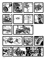 2
2
-
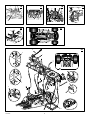 3
3
-
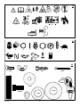 4
4
-
 5
5
-
 6
6
-
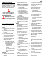 7
7
-
 8
8
-
 9
9
-
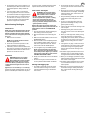 10
10
-
 11
11
-
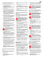 12
12
-
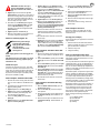 13
13
-
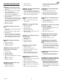 14
14
-
 15
15
-
 16
16
-
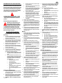 17
17
-
 18
18
-
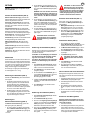 19
19
-
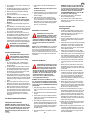 20
20
-
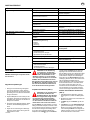 21
21
-
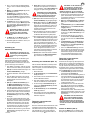 22
22
-
 23
23
-
 24
24
-
 25
25
-
 26
26
-
 27
27
-
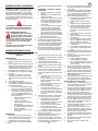 28
28
-
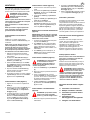 29
29
-
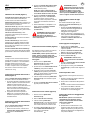 30
30
-
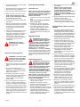 31
31
-
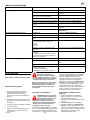 32
32
-
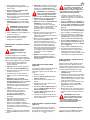 33
33
-
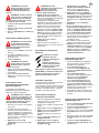 34
34
-
 35
35
-
 36
36
-
 37
37
-
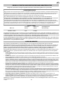 38
38
-
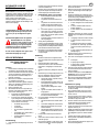 39
39
-
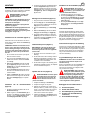 40
40
-
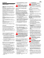 41
41
-
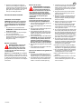 42
42
-
 43
43
-
 44
44
-
 45
45
-
 46
46
-
 47
47
-
 48
48
-
 49
49
-
 50
50
-
 51
51
-
 52
52
-
 53
53
-
 54
54
-
 55
55
-
 56
56
-
 57
57
-
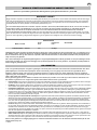 58
58
-
 59
59
-
 60
60
-
 61
61
-
 62
62
-
 63
63
-
 64
64
-
 65
65
-
 66
66
-
 67
67
-
 68
68
-
 69
69
-
 70
70
-
 71
71
-
 72
72
-
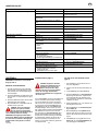 73
73
-
 74
74
-
 75
75
-
 76
76
-
 77
77
-
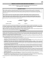 78
78
-
 79
79
-
 80
80
-
 81
81
-
 82
82
-
 83
83
-
 84
84
-
 85
85
-
 86
86
-
 87
87
-
 88
88
-
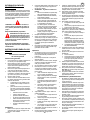 89
89
-
 90
90
-
 91
91
-
 92
92
-
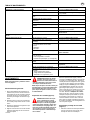 93
93
-
 94
94
-
 95
95
-
 96
96
-
 97
97
-
 98
98
-
 99
99
-
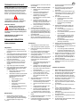 100
100
-
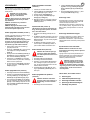 101
101
-
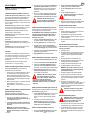 102
102
-
 103
103
-
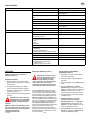 104
104
-
 105
105
-
 106
106
-
 107
107
-
 108
108
-
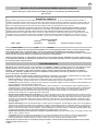 109
109
-
 110
110
-
 111
111
-
 112
112
-
 113
113
-
 114
114
-
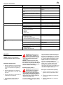 115
115
-
 116
116
-
 117
117
-
 118
118
-
 119
119
-
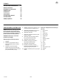 120
120
-
 121
121
-
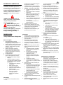 122
122
-
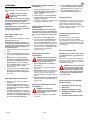 123
123
-
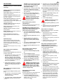 124
124
-
 125
125
-
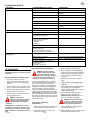 126
126
-
 127
127
-
 128
128
-
 129
129
-
 130
130
-
 131
131
-
 132
132


Murray Lawn Mower 385048x51A Manuale utente
- Tipo
- Manuale utente
in altre lingue
Documenti correlati
Altri documenti
-
Simplicity 7800411 Manuale utente
-
-
-
-
-
-
-
-
 EMAK RIDING MOWER Manuale del proprietario
-
Texas 7600 Lawn Tractor Rider Manuale utente
