
3
Certificate No. FM 39709
ISO
9001
ANSI A14.3
prEN353-1:2014+A1:2017
CSA Z259.2.5
141 kg/
310 lbs
7
1
A
B
C
E
D
â
x1
á
x4
6
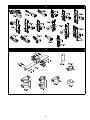
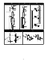
INSTALLATION INSTRUCTIONS
1
No. 2777
Satra Technology Europe Ltd
Bracetown Business Park
Clonee,
Dublin
D15 YN2P, Ireland
CE TYPE TEST
CE
PRODUCTION
QUALITY
CONTROL
5
4
BSI (0086)
Kitemark Court
Davy Ave, Knowlhill
Milton Keynes
MK5 8PP, UK
LAD-SAF
™
Flexible Cable Ladder
Safety Systems
2
© 3M 2019

FORM NO: 5908247 REV: A
2
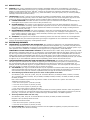
SAFETY INFORMATION
Please read, understand, and follow all safety information contained in these instructions prior to the use of this Vertical
System. FAILURE TO DO SO COULD RESULT IN SERIOUS INJURY OR DEATH.
These instructions must be provided to the user of this equipment. Retain these instructions for future reference.
Intended Use:
This Vertical System is intended for use as part of a complete personal fall protection system.
Use in any other application including, but not limited to, material handling, recreational or sports related activities, or other activities not
described in the Product Instructions, is not approved by 3M and could result in serious injury or death.
This device is only to be used by trained users in workplace applications.
! WARNING
This Flexible Cable/Rigid Rail System is part of a personal fall protection system. It is expected that all users be fully trained in the
safe installation and operation of their personal fall protection system. Misuse of this device could result in serious injury or
death. For proper selection, operation, installation, maintenance, and service, refer to these Product Instructions and all manufacturer
recommendations, see a supervisor, or contact 3M Technical Service.
• To reduce the risks associated with working with a Flexible Cable/Rigid Rail System which, if not avoided, could result
in serious injury or death:
- Inspect all components of the system before each use, at least annually, and after any fall event. Inspect in accordance with the
Product Instructions.
- If inspection reveals an unsafe or defective condition in a component of the system, remove the component from service and
destroy it.
- Any Flexible Cable/Rigid Rail System that has been subject to fall arrest or impact force must be immediately removed from
service and all components must be inspected by a Competent Person prior to being used again.
- Do not connect to the system while it is being installed.
- Ensure the system is appropriately rated for the number of simultaneous users.
- When unpacking the cable it may rapidly uncoil. Use proper safety procedures and appropriate personal protective equipment
when unpacking cable.
- Only use approved connectors to attach body harness to the system. Do not use any additional connecting devices.
- Use only cable specied and approved in the Product Instructions.
- Do not interfere with the locking action of the shuttle/sleeve device. Only manipulate the device to attach and detach from the
system.
- Always maintain three points of contact while climbing. Refer to the Product Instructions for further information on proper
climbing technique.
- Ensure that fall protection systems/subsystems assembled from components made by different manufacturers are compatible
and meet the requirements of applicable standards, including the ANSI Z359 or other applicable fall protection codes, standards,
or requirements. Always consult a Competent and/or Qualied Person before using these systems.
• To reduce the risks associated with working at height which, if not avoided, could result in serious injury or death:
- Ensure your health and physical condition allow you to safely withstand all of the forces associated with working at height.
Consult with your doctor if you have any questions regarding your ability to use this equipment.
- Never exceed allowable capacity of your fall protection equipment.
- Never exceed maximum free fall distance of your fall protection equipment.
- Do not use any fall protection equipment that fails pre-use or other scheduled inspections, or if you have concerns about the use
or suitability of the equipment for your application. Contact 3M Technical Services with any questions.
- Some subsystem and component combinations may interfere with the operation of this equipment. Only use compatible
connections. Consult 3M prior to using this equipment in combination with components or subsystems other than those described
in the User Instructions.
- Use extra precautions when working around moving machinery (e.g. top drive of oil rigs), electrical hazards, extreme
temperatures, chemical hazards, explosive or toxic gases, sharp edges, or below overhead materials that could fall onto you or
your fall protection equipment.
- Use Arc Flash or Hot Works devices when working in high heat environments.
- Avoid surfaces and objects that can damage the user or equipment.
- Ensure there is adequate fall clearance when working at height.
- Never modify or alter your fall protection equipment. Only 3M or parties authorized in writing by 3M may make repairs to the
equipment.
- Prior to use of fall protection equipment, ensure a rescue plan is in place which allows for prompt rescue if a fall incident occurs.
- If a fall event occurs, immediately seek medical attention for the worker who has fallen.
- Do not use a body belt for fall arrest applications. Use only a Full Body Harness.
- Minimize swing falls by working as directly below the anchorage point as possible.
- If training with this device, a secondary fall protection system must be utilized in a manner that does not expose the trainee to
an unintended fall hazard.
- Always wear appropriate personal protective equipment when installing, using, or inspecting the device/system.
EN

3
FOREWORD
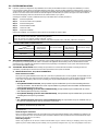
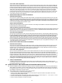
This instruction manual describes the installation of the Lad-Saf
™
Flexible Cable Ladder Safety Systems. It should be used as
part of an employee training program as required by OSHA, ANSI, CSA, and CE, and must be kept with the equipment.
5 To avoid serious injury or death follow the safety information in these instructions.
5 Installers must read and follow the manufacturer’s instructions for safety equipment used with this system.
5 Proper fall protection must be used while installing this system.
5 If you have questions on the installation or suitability of this equipment for your application, contact DBI-SALA.
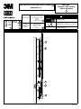
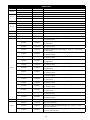
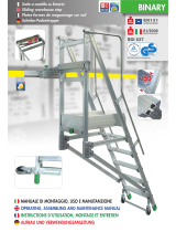
GLOSSARY REFERENCES
Numbered Glossary References on the front cover of this instruction reference the following items:
1
Installation Instructions
2
Lad-Saf
™
Flexible Cable Ladder Safety Systems
3
Standards
4
Number of notied body that performed
CE Test.
5
Number of notied body checking the manufacture of this PPE.
6
Maximum number of users.
7
Maximum user weight is 141 kg (310 lbs) including tools, other equipment and clothing.
Lad-Saf
™
Flexible Cable Ladder Safety System Components, Figure 1:
A Top Bracket
B Cable
C Cable Guide
D i-Safe RFID Tag
E Bottom Bracket
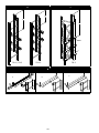
Part Lists And Part References
The parts that can comprise a typical Lad-Saf
™
Ladder Safety System are listed in the Parts List Table in this manual. Some
items may have multiple part options and part numbers. The “Item” column on the left side of each part list is associated with
one or more part numbers found in the columns to right (for example: TB-1, BB-5, etc.) that can be used for installation. The
installation situation will determine which parts must be used.
EN

4
1.0 APPLICATIONS
When used in combination with the Lad-Saf™ Detachable Cable Sleeve (sold separately), the Lad-Saf™
Flexible Cable Ladder Safety System (Figure 1) is designed to protect a worker in the event of a fall while climbing xed
ladders or similar climbing structures. LAD-SAF
™
systems are intended to be installed on xed ladders or ladder like
climbing surfaces that are part of a structure (e.g., water tank ladders, mono poles [wood, steel, or concrete] buildings,
manways, antenna structures and towers).
LAD-SAF
™
systems are not intended to be installed on portable ladders. These systems are designed
for use on ladders that are generally vertical. The ladder safety system must not exceed a maximum angle of 15° from
vertical. The following application limitations must be considered before installing the LAD-SAF
™
system.
The ladder structure to which the system is installed must be capable of withstanding the
loads applied by the system in the event of a fall (see Section 2.2).
The number of users allowed on the system at one time varies depending on the type of
system and installation. Generally, system capacities range from one to four users. See sections 2.0 and 3.0 for more
information on capacity limitations. System capacities are based on a maximum user weight, including tools and
clothing, of 310 lbs (140.6 kg).
Use of this equipment in areas with environmental hazards may require that
additional precautions be taken to reduce the possibility of injury to the user or damage to the equipment. (e.g., high
heat caused by welding or metal cutting, caustic chemicals, seawater, high voltage power lines, explosive or toxic
gases, moving machinery, sharp edges).
This equipment is intended to be installed by persons who have been trained in its correct application.
Refer to applicable local, and national requirements governing this equipment for more information on ladder safety
systems and associated components, including OSHA 1910.27.
2.0 SYSTEM REQUIREMENTS
This equipment is designed for use with DBI-SALA approved
components and subsystems. The use of non-approved components and subsystems (e.g., harnesses, lanyards, sleeves,
etc.) may jeopardize compatibility of equipment, and could aect the safety and reliability of the complete system. If you
have questions on the installation or suitability of this equipment for your application, contact DBI-SALA.
The DBI-SALA Lad-Saf™ Ladder Safety Systems, including the DBI-
SALA Lad-Saf™ Detachable Cable Sleeves, are designed for use with DBI-SALA approved climb assist systems. The use of
any other type of climb assist system, including a powered climb assist system, may be incompatible with the Lad-Saf™
Ladder Safety System and Detachable Cable Sleeves, and could create a serious safety hazard for the user. Do not use
non-DBI-SALA climb assist systems without rst consulting a competent person and/or a qualied person at your worksite
for approval. If you have additional questions about compatibility, please contact 3M Technical Services.
The climbing structure to which the
LAD-SAF
™
system is installed must be capable of supporting the loads imposed by the system. For calculation purposes
the required bracket load may be assumed to be distributed evenly between the number of rung attachments. For
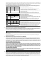
example, the TB-3 top bracket (Figure 2) is supplied with three rung connections. The load required for each rung for a
single user system is 1,125 lbs (5.0 kN) per rung (3,375 lbs [15.0 kN]/3).
(See Figure 2 and TB Items Part List) The top bracket connection loads include system pretension
and forces associated with arresting a fall. Load requirements for the top bracket vary depending on the number of
users allowed on the system at one time, top bracket model, and type of connection to the structure.
Item Numbers; TB-2, TB-3, TB-4, TB-6, TB-7, TB-10 and Part Numbers; 6116048, 6116050, 6116051, 6116052,
TB-1, 6116055, 6116057, 6116059, TB-5, 6116282, 6116286, 6116290, 6116291, 6116292, 6116293, 6116294,
6116295, 6116296.
Note: Other installation requirements may limit the number of users allowed on a system. See section 3.0.
Top Bracket Connection Loads:
• One user on the system: 3,375 lbs (15.0 kN)
• Two users on the system: 4,350 lbs (19.3 kN)
• Three users on the system: 5,325 lbs (23.7 kN)
• Four users on the system: 6,300 lbs (28.0 kN)
Exception: TB-1 top bracket is designed for use with 6116336 or 6116337 grab bar extension. When the grab bar is
used as a connection for a personal fall arrest system the bracket connection must support a minimum of 5,000 lbs
(22.2 kN)., or 3,600 lbs (16.0 kN) for a certied anchorage. See ANSI Z359.1 and OSHA regulations.
Item Numbers; TB-8, TB-9, TB-11 and Part Numbers 6116074, 6116325, 6116324 and 6116328.
Exception: TB-9 (6116074) allows two users.
Top Bracket Connection Loads:
• One user on the system: 3,375 lbs (15.0 kN)
• Two users on the system: 4,350 lbs (19.3 kN)
The bottom bracket connection must be capable of supporting a system pretension load of
750 lbs (3.3 kN) in the direction of loading.

5
3.0 SYSTEM INSTALLATION
LAD-SAF
™
systems are designed for easy installation onto a variety of xed ladder structures. To begin the installation you need to
know the model numbers of the top and bottom brackets, cable guides, and type of cable (galvanized or stainless steel). Figures 2, 3,
4 and 5 identify most models. Some brackets are designed to be installed using stand-o supports which go between the bracket and
structure. You need to know model numbers of stand-o supports if included with your system. See Figure 5 for model numbers of
most stand-o supports. Follow the instructions for the models included in your system.
Generally, the LAD-SAF
™
system is installed from the top of the ladder down. The basic procedure is:
Install the top bracket
Connect the cable to the top bracket
Install the cable guides
Install the bottom bracket
Tension the cable
Inspect the installation
Planning the installation can minimize the amount of time on the ladder and improve safety.
; Use personal fall arrest or restraint systems when exposed to a fall hazard while installing LAD-SAF
™
systems.
; Do not connect to the LAD-SAF
™
system being installed.
; Do not connect to a partially installed LAD-SAF
™
system.
; Use caution when installing LAD-SAF
™
systems near electrical power lines. LAD-SAF
™
cables are conductive.
Bracket Type
Cable and Fitting Type
Stainless Cable
with Stainless
Swage Fitting
Stainless Cable
with Carrier Clamp
Galvanized Cable
with Stainless
Swage Fitting
Galvanized Cable
with Carrier Clamp
Stainless Y N N N
Galvanized O N Y Y
Y = recommended component combination. O = optional. N = not recommended
Do not use carrier clamps with stainless steel cables.
Some installations require welding brackets to the structure. DBI-SALA recommends that welding
be completed by a certied professional welder in accordance with applicable national welding codes or standards. Base and ller
materials must be compatible with galvanized or stainless steel, depending on the materials of your system. Protect nished welds
from corrosion with coating or paint.
Before installing the top bracket it is recommended that the ladder or climbing structure be
evaluated by a qualied person to determine if the load requirements for the system are satised.
Direct Connection to Ladder:
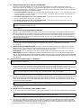
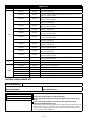
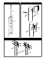
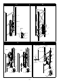
See Figure 6 for typical installations of the TB-2, TB-3, and TB-10 top brackets onto a round rung ladder. The top bracket should
be positioned to allow users safe access when connecting or disconnecting from the system. The top bracket is typically mounted
in the center of the climbing surface for ease of climbing, but may be located towards the side of the ladder if required.
TB-3, TB-10:
• For systems limited to one user, the top bracket may be installed with up to four feet extending above the
top rung connection. This will allow the use of only two ladder rung clamps. Ensure the ladder will withstand the
required loads between the two rungs.
• the top bracket may be installed with up to three
feet extending above the top rung connection.
• , the top bracket may be installed with up to two feet
extending above the top rung connection.
TB-2:
• the top bracket may be installed with up
to ve feet extending above the top bracasket connection.
; One rung clamp (two for the TB-10 bracket) is designed to bolt through the bracket and onto the rung. This clamp must not
be omitted, or the bracket may slip under load.
Install rung clamps using the hardware provided. Do not substitute other fasteners. Torque fasteners to 20-25 ft-lbs
(27.1-33.9 N-m).
Stand-o Support Connection:
Figure 7 shows the installation of the TB-3 top bracket using a horizontal stand-o bracket. These installations are limited to one
user on the system at a time. Use hex bolts in place of U-bolts to attach the TB-3 top bracket to the horizontal stand-o. Torque
fasteners to 20-25 ft-lbs (27.1-33.9 N-m).
Ladder Rung Support:
Ladder rung supports can be used to reinforce hollow ladder rungs to reduce crushing or collapsing of the rung due to
tightening of the Ladder Safety System Clamps, and to generally strengthen the rung. The Rung Support must have

6
sucient length extending on either side of the Ladder Side Rails to install Rung Support fasteners. Install ladder rung
support at each LAD-SAF
™
component connection point. The ladder and its connection to the structure must be evaluated
by a qualied person to determine if the load requirements for the system are met.
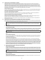
Ladder Rung Supports are available in various shapes and lengths. For best results, select a Ladder Rung Support
size that will t closely with the inside dimensions of the rung. See Figure 8 for examples of ladder rung supports.
A, Figure 8
Model Ø R
Install at each point indicated below:
6100187 1 in (2.5 cm) 22 in (56 cm) 1. Slide the Rung Support through the open rung.
2. Slide Washers over each end of the Rung Support and secure with Nuts.
Tighten Nuts until Washer’s are ush against the Ladder Rail.
3. Insert Cotter Pins through the holes in each end of the Rung Support. Cotter
Pins should inserted from the top of the Rung Support to prevent them from
dropping out of the holes.
4. Separate and bend the Cotter Pin Legs to ensure Cotter Pins stay in the
holes and the Rung Supports can not slide out of the Ladder Rung.
6100188 1 in (2.5 cm) 26 in (66 cm)
6100189 1 in (2.5 cm) 30 in (76 cm)
Materials Aluminum Bar, Stainless Steel
Fasteners
B, Figure 8
Model Ø R
Install at each point indicated below:
6100151 1 in (2.5 cm) 17 in (43 cm) 1. Slide the Rung Support through the open rung.
2. Insert Cotter Pins through the holes in each end of the Rung Support. Cotter
Pins should inserted from the top of the Rung Support to prevent them from
dropping out of the holes.
3. Separate and bend the Cotter Pin Legs to ensure Cotter Pins stay in the
holes and the Rung Supports can not slide out of the Ladder Rung.
Materials Aluminum Bar, Stainless Steel
Fasteners
C, Figure 8
Model R
Install at each point indicated below:
6100186 .59 in
(2.5 cm)
1 in
(2.5 cm)
19 in
(48 cm)
1. Slide the Rung Support through the open rung.
2. Insert Cotter Pins through the holes in each end of the Rung Support. Cotter
Pins should inserted from the top of the Rung Support to prevent them from
dropping out of the holes.
3. Separate and bend the Cotter Pin Legs to ensure Cotter Pins stay in the
holes and the Rung Supports can not slide out of the Ladder Rung.
Materials Aluminum Bar, Stainless Steel
Fasteners
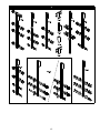
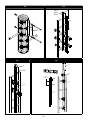
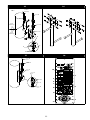
See Figure 9 for a typical installation of the TB-1 top bracket onto a round rung ladder. The top bracket should be positioned to
allow users safe access when connecting or disconnecting from the system. The top bracket is typically mounted in the center of
the climbing surface for ease of climbing, but may be located towards the side of the ladder if required.
; The top rung clamp bolts through a plate that is welded onto the bracket. This rung clamp must not be
omitted, or the bracket may slip under load.
Install rung clamps using the hardware provided. Do not substitute other fasteners. Torque fasteners to 20-25 ft.-lbs
(27.1-33.9 N-m).
The 6116336 grab bar (A) is installed by sliding the grab bar into the square tube of the TB-1 top bracket and installing the
detent pin (C) into the grab bar.
See Figure 10 for a typical installation of the TB-4, TB-6, and TB-7 top brackets. The top bracket should be positioned to allow
users safe access when connecting or disconnecting from the system. The top bracket is typically mounted in the center of the
climbing surface, directly above the ladder, for ease of climbing, but may be located towards the side of the ladder, 12 inches
(30.5 cm) maximum from center, if required. The top brackets are to be connected to the structure with a DBI-SALA (model SO-2
stand-o in Figure 10) or customer supplied stand-o support. Stand-o supports must support the loads specied in section 2.2,
and must be compatible with the LAD-SAF
™
system.
Angle Leg and Round Leg Stand-o Installation:
See Figure 11 for the installation of the angle (example: SO-4) and round leg (example: SO-5) stand-o supports. Install stand-
o supports using the hardware provided. Do not substitute other fasteners. Torque 3/8-inch fasteners to 20-25 ft-lbs (27.1-33.9
N-m). Install the top bracket to the stand-o support using the 1/2-inch fasteners provided. Torque 1/2-inch fasteners to 40-45
ft-lbs (54-61 N-m). Note: For the TB-6 stand-o, fasteners are not supplied. DBI-SALA recommends using lock washers, double
nuts, or other methods to ensure fasteners will not loosen.
SO-2 Weld-on Stand-o Installation:
Install the SO-2 stand-o support as shown in Figure 10. See section 3.3 for welding recommendations. The stand-o must be
perpendicular to the pole surface and in-line with the carrier cable.
; Installations that use the angle leg or round leg stand-o support brackets are limited to one user on the system at a time.
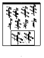
See Figure 12 for a typical installation of the TB-5 top bracket onto a wooden pole. The top bracket should be positioned to allow
users safe access when connecting or disconnecting from the system. The top bracket is typically mounted in the center of the
climbing surface for ease of climbing, but may be located towards the side of the ladder if required. Use 1/2-inch fasteners (not
provided) to attach the top bracket to the pole. Fasteners should extend through the pole when possible. DBI-SALA recommends
using lock washers, double nuts, or other methods to ensure fasteners will not loosen.

7
See gure 13 for a typical installation of TB-9, TB-13, and TB-14 top brackets onto a ladder. Some brackets utilize rung
spacers while others do not (see Figure 2). The top bracket should be positioned to allow users safe access when connecting or
disconnecting from the system. The top bracket is typically mounted in the center of the climbing surface for ease of climbing, but
may be located towards the side of the ladder if required.
• For systems limited to one user, the top bracket may be installed with up to 4 ft. (1.2 m) extending above the
top rung connection. This will allow the use of only two ladder rung clamps. Ensure the ladder will withstand the
required loads between the two rungs.
• , the top bracket may be installed with up to 3 ft.
(0.9 m) extending above the top rung connection.
• , the top bracket may be installed with up to 2 ft.
(0.6 m) extending above the top rung connection.
; One rung clamp (lower connection) is designed to bolt through the bracket and onto the rung. This clamp must not be
omitted, or the bracket may slip under load.
Install rung clamps using the hardware provided. Do not substitute other fasteners. Torque fasteners to 20-25 ft-lbs
(27.1-33.9 N-m).
See Figure 14 for a typical installation of the TB-8 top bracket onto a round rung ladder. The top bracket should be positioned to
allow users safe access when connecting or disconnecting from the system. The top bracket is typically mounted in the center of
the climbing surface for ease of climbing, but may be located towards the side of the ladder if required. The TB-8 top bracket is
designed to mount at or near the top of the ladder and telescope up when in use. Typical installations include access ladders into
manholes and under trap doors.
; When using TB-8 telescoping top bracket, use only the swaged end tting in the top bracket.
Installations that use the TB-8 top bracket are limited to one user on the system at a time.
Install rung clamps using the hardware provided. Do not substitute other fasteners. Torque fasteners to 20-25 ft-lbs
(27.1-33.9 N-m).
See Figure 15. The D-ring Anchorage (6100219) is designed for used with the
DBI-SALA Force2
™
energy absorbing lanyard and full body harness. The D-ring Anchorage must be attached to a Lad-Saf
™
top
bracket (A) that is attached to a structure that meets the top bracket load requirements.
APPLICATION: The D-ring anchorage must be used in accordance with local requirements for fall arrest or rescue systems.
INSTALLATION: See Figure 15. Install the D-ring anchorage assembly (B) no more than 6 in. (15.2 cm) above the ladder rung (C)
where the top clamp plate (D) of the Lad-Saf
™
top bracket is attached. The D-ring must be on the climbing (cable) side of the top bracket.
Clamp the D-ring anchorage assembly to the top bracket with the fasteners provided with the assembly. Torque fasteners to 20-25 ft.-lbs
(27.1-33.9 N-m).
; Keep the carrier cable and carrier clamp clean during installation. Contamination of the carrier clamp or cable could
cause the clamp to malfunction.
Lay the carrier cable out on the ground in a clean area by rolling the coil. Do not pull cable from center of coil. For some
installations it may be easier to lower the carrier cable from the top connection level down to the bottom bracket. If so, carefully
lower the cable by unspooling without twisting the cable at the top connection. Do not drop the cable to the lower level.
; Carrier cable is very sti and may spring out of coil unexpectedly. Use proper safety procedures when unrolling
cable. Use appropriate safety gear, including gloves and safety glasses, when unrolling cable.
Inspect the cable for shipping damage before proceeding. Do not install damaged cable.
See Figure 16 for installation of the galvanized carrier cable into the top bracket. Ensure the end of cable (A) is free of kinks and unraveled
strands. Pass the cable up through the top bracket pipe (B) and the urethane shock absorber (C). Install the carrier clamp (D) and
washer (E) onto cable with the cone of carrier clamp pointing down. At least 1.0 in. (2.5 cm), but no more than 2 in. (5.1 cm). of cable
must protrude through the carrier clamp.
; Excess cable protruding through the carrier clamp may prevent installation of the cap. If this occurs, cut o
extra cable. Do not remove carrier clamp from cable to avoid damage to the carrier clamp.
Seat the carrier clamp into shock absorber by pulling rmly on carrier clamp below the top bracket pipe. Install cap (F) by seating
it rmly onto the pipe.
Lay the carrier cable out on the ground in a clean area by rolling the coil. Do not pull the cable from the center of the
coil.
; Carrier cable is very sti, and may spring out of the coil unexpectedly. Use caution when unrolling cable. Use
appropriate safety gear, including gloves and safety glasses, when unrolling cable.
Inspect the cable for shipping damage before proceeding. Do not install damaged cable.
See Figure 17 for installation of a stainless steel carrier cable into the top bracket. All stainless steel carrier cables are supplied
with a swagged end tting for connection to the top bracket. To install the carrier cable (A), feed the free end of the cable down
through the washer (D), urethane shock absorber (C) and top bracket pipe (B) until the swage tting (E) is rmly seated into the
shock absorber. Install the cap (F) by seating it rmly onto the pipe.

8
Cable guides protect the carrier cable from chang against the ladder or structure and to prevent the climber from
excessively
deecting the cable from side to side. Cable guides should be positioned at approximately 25 ft (7.62 m) intervals along the carrier
cable between the top and bottom brackets, and at any point along the system where the cable may
abrade against the structure.
Cable guides should be staggered along the system to reduce harmonic eects of the wind, such as at 23 (7.01), 25 (7.61), and 27
(8.23) feet (m) intervals. For high wind areas “L” shaped cable guides may be used. The “L” shaped cable guides should be alternated
with opening on the left, then right, etc. up the ladder. Latching cable guides are also available.
Direct Connection to Ladder:
See Figure 18 for typical installations of cable guides onto a ladder. (A = CG-15, B = CG-3, C = CG-5) Some cable guides utilize rung
spacers and clamp plates while others do not (see Figure 4). Install the cable guide using the hardware provided. Do not substitute
other fasteners. Torque fasteners to 20-25 ft-lbs (27.1-33.9 N-m).
SO-7 Weld-on Stand-o Support Installation:
Install the SO-7 stand-o as shown in Figure 19. See section 3.3 for welding recommendations. The stand-o (A [model SO-7 is
shown]) must be perpendicular to the pole surface and in-line with the carrier cable. (B = cable guide)
Angle Leg and Round Leg Stand-o Support Installation:
See Figure 20 for typical installations of angle leg (A) and round leg (B) stand-o supports. Install the stand-o support using the
hardware provided. Do not substitute other fasteners. Torque fasteners to 20-25 ft-lbs (27.1-33.9 N-m).
Install the cable guide to the stand-o support using the hardware provided. Do not substitute other fasteners. Torque fasteners to
20-25 ft-lbs (27.1-33.9 N-m).
Before installing the bottom bracket it is recommended that the ladder and/or climbing structure be evaluated by a qualied engineer
to determine if the load requirements for the system specied in section 2.2 are met.
; Depending on the length of the system, and the environment in which the system is installed, it may be
necessary to periodically re-tension the system. Extreme temperature ranges and very long systems will likely
require periodic re-tensioning. The tension indicator can be purchased separately (9504239). Contact DBI-SALA
for details.
Direct Connection to Ladder:
See Figure 21 for a typical installation of the bottom bracket onto a ladder. Some brackets utilize “U”-bolts while others utilize bolts
and clamp plates to attach to the ladder (see Figure 3). The bottom bracket should be positioned to allow users safe access when
connecting or disconnecting from the system. The bottom bracket must be mounted in-line (vertically) with the top bracket.
; One rung clamp is designed to bolt through the bracket and onto the rung. This clamp must not be omitted, or the bracket
may slip under load.
Install the rung clamps using hardware provided. Do not substitute other fasteners. Torque fasteners to 20-25 ft-lbs (27.1-33.9
N-m).
Stand-o Support Connection:
Figure 22 shows the installation of the bottom brackets using a horizontal stand-o bracket. Use U-bolts to attach to support leg
(A). Use hex bolts provided in place of U-bolts to attach the bottom bracket to the horizontal stand-o (B). Torque fasteners to
20-25 ft-lbs (27.1-33.9 N-m).
Carrier Cable Tension Adjustment:
Figure 21 shows the assembly of the tension rod to the bottom bracket and carrier cable (A). Loosely clamp the saddle clips
(B) around the carrier cable. Slide the tension rod (C) down the carrier cable and through the hole in the bracket until sucient
threads are exposed to allow the installation of the tension indicator (D), washers (E), and nuts (F and G). Remove the slack in the
carrier cable by the pulling cable though the saddle clips. Tighten saddle clips to 35 ft.-lbs (47.5 N-m). Tighten the tensioning nut
(F) until the ring on the tension indicator is sheared o. A small amount of grease on the tension rod threads will reduce the eort
required to tension the carrier cable. If there are insucient threads exposed to fully tension the carrier cable, pull more carrier
cable through the saddle clips on the tension rod and repeat the procedure. When correct carrier cable tension is reached tighten
the jam nut (G) against the tensioning nut. Cut o excess cable just below the lower saddle clip.
Bottom Bracket Installation:
See Figure 23 for typical installations of the BB-4 and BB-6 bottom brackets onto a round rung ladder. See Figure 24 for a typical
installation of the BB-5 bottom bracket with a weld-on stand-o support. The bottom bracket should be positioned to allow users
safe access when connecting or disconnecting from the system. The bottom bracket must be mounted in-line (vertically) with the
top bracket.
; One rung clamp is designed to bolt through the bracket and onto the rung. This clamp must not be omitted,
or the bracket may slip under load.
Install the rung clamps using the hardware provided. Do not substitute other fasteners. Torque fasteners to 20-25 ft.-
lbs (27.1-33.9 N-m).
Weld-on Stand-o Installation:
Install the SO-2 stand-o support as shown in Figure 24. See section 3.3 for welding recommendations. The stand-o must be
perpendicular to the pole surface and in-line with the carrier cable.

9
Carrier Cable Tension Adjustment:
Figures 23 and 24 show the assembly of the tension rod to the bottom bracket and carrier cable. Loosely clamp the saddle clips
around the carrier cable (A). Slide the tension rod (C) down the carrier cable and through the hole in the bracket until sucient
threads are exposed to allow the installation of the washers (E) and nuts (F and G). Remove slack in the carrier cable by pulling
the cable through the saddle clips. Tighten the saddle clips to 35 ft.-lbs (47.5 N-m). Tighten the tensioning nut (F) until the carrier
cable is taut. A small amount of grease on the tension rod threads will reduce the eort required to tension the carrier cable.
Compress the spring to approximately 5-1/2 in. (14 cm) (H). Do not completely compress the spring. If there are insucient
threads exposed to fully tension the carrier cable, pull more carrier cable through the saddle clips on the tension rod and repeat
the procedure. When the correct carrier cable tension is reached, tighten the jam nut against the tensioning nut (G). Cut o
excess cable just below the lower saddle clip.
Bottom Bracket Installation:
See Figure 25 for a typical installation of the BB-7 bottom brackets. The bottom bracket should be positioned to allow users safe
access when connecting or disconnecting from the system. The bottom bracket must be mounted in-line (vertically) with the top
bracket. The 6100035 and 6100040 bottom brackets are designed to be connected to the structure using a DBI-SALA or customer
supplied stand-o support. Customer supplied stand-o supports must be capable of withstanding the loads specied in section
2.2 and must be compatible with the LAD-SAF
™
system.
Weld-on Stand-o Installation:
Install the SO-2 stand-off support as shown in Figure 25. See section 3.3 for welding recommendations. The stand-off must be perpendicular to
the pole surface and in-line with the carrier cable.
Angle Leg and Round Leg Stand-o Installation:
See Figure 26 for the installation of angle (A) and round (B) leg stand-off supports. Install stand-off supports using the hardware provided. Do not
substitute other fasteners. Torque 3/8 inch fasteners to 20-25 ft.-lbs (27.1-33.9 N-m). Install bottom bracket to stand-off support using 1/2-inch
fasteners provided. Torque 1/2-inch fasteners to 40-45 ft.-lbs (54-61 N-m).
Carrier Cable Tension Adjustment:
Figure 25 shows the assembly of the tension rod to the bottom bracket and carrier cable (A). Loosely clamp the saddle clips (B) around
the carrier cable. Slide the tension rod (C) down the carrier cable and through the hole in the bracket until sucient threads are exposed
to allow the installation of the tension indicator (D), washers (E), and nuts (F and G). Remove slack in the carrier cable by pulling the
cable though the saddle clips. Tighten saddle clips to 35 ft.-lbs (47.5 N-m). Tighten the tensioning nut (F) until the ring on the tension
indicator is sheared o. A small amount of grease on the tension rod threads will reduce the eort required to tension the carrier cable. If
there are insucient threads exposed to fully tension the carrier cable, pull more carrier cable through the saddle clips on the tension rod
and repeat the procedure. When the correct carrier cable tension is reached, tighten the jam nut (G) against the tensioning nut. Cut o
excess cable just below the lower saddle clip.
Bottom Bracket Installation:
See Figure 27 for a typical installation of the BB-8 bottom bracket. The bottom bracket should be positioned to allow users safe
access when connecting or disconnecting from the system. The bottom bracket must be mounted in-line (vertically) with the
top bracket. Use 1/2-inch fasteners (not provided) to attach the bottom bracket to the pole. DBI-SALA recommends using lock
washers, double nuts, or other methods to ensure fasteners will not loosen.
Carrier Cable Tension Adjustment:
Figure 27 shows the assembly of the tension rod to the bottom bracket and carrier cable. Loosely clamp the saddle clips around
the carrier cable. Slide the tension rod down the carrier cable and through the hole in the bracket until sucient threads are
exposed to allow the installation of the tension indicator, washers, and nuts. Remove slack in the carrier cable by pulling the cable
though the saddle clips. Tighten saddle clips to 35 ft.-lbs (47.5 N-m). Tighten the tensioning nut until the ring on the tension
indicator is sheared o. A small amount of grease on the tension rod threads will reduce the eort required to tension the carrier
cable. If there are insucient threads exposed to fully tension the carrier cable, pull more carrier cable through the saddle clips
on the tension rod and repeat the procedure. When the correct carrier cable tension is reached, tighten the jam nut against the
tensioning nut. Cut o excess cable just below the lower saddle clip.
To install the 5900172 counterweight onto the carrier cable, loosen the saddle clips and pass the carrier cable through the
counterweight. Position the counterweight to allow users safe access when connecting or disconnecting from the system. Tighten
the saddle clips against the carrier cable.
4.0 IDENTIFICATION AND INSPECTION AFTER SYSTEM INSTALLATION:
Install the installation and service label onto the ladder or structure in a prominent location. Use the steel wire provided with the
label to attach it to the ladder or structure. Before installing the label, mark the installation date and number of users allowed in
the appropriate locations on the label. Use a metal letter stamp to mark the label. Record the system identication information in
the Installation Checklist at the end of this manual.
After installation conduct a nal inspection of the system as follows:
• Ensure all fasteners are in place and properly tightened.
• Ensure the carrier cable is properly tensioned. Do not use the Lad-Saf
™
system if the bottom of the cable is not secured/
tensioned with the bottom bracket assembly.
• For cables terminated with a carrier clamp, the cable should extend above the carrier clamp 1.0 in. - 2.0 in. (2.5 cm - 5.0 cm).
• Ensure the carrier cable does not abrade against the structure at any point.
• Ensure the system information is recorded on the label.

10
5.0 INSPECTION
The Lad-Saf
™
system includes a Radio Frequency Identication (RFID) tag (Figure 28). The RFID tag can be used in
conjunction with a handheld reading device and web based portal to simplify inspection and inventory control and provide
records for your fall protection equipment. If you are a rst-time user, contact a 3M Fall Protection Customer Service
representative (see back cover). If you have already registered, go to www.3M.com/FallProtection. Follow the instructions
provided with your handheld reader or on the web portal to transfer your data to your web log..
6.0 MAINTENANCE, SERVICING, STORAGE
If the carrier cable becomes heavily soiled with oil, grease, paint, or other substances, clean it with warm soapy water. Wipe o the
cable with a clean, dry cloth. Do not force dry with heat. Do not use acid or caustic chemicals that could damage the cable.
7.0 SPECIFICATIONS
All top and bottom brackets, cable guides, carrier cable, and fasteners are made of galvanized or stainless steel. Contact DBI-SALA for
material specication details if required. The LAD-SAF™ system, when installed according to the installation instructions, meets OSHA,
ANSI (ANSI A14.3), CSA (Z259.2.5) and CE (prEN353-1:2014+2017:A1) requirements.
8.0 LAD-SAF SYSTEM LABELING
; Please reference the User Manual supplied with the Lad-Saf™ X2 Detachable Sleeve for proper use and maintenance of this
system.
Lad-Saf System:
The Lad-Saf Flexible Cable Ladder Safety System label must be securely attached and fully legible. (See Figure 28) Label Contents:
1. Acceptable cable sleeve part numbers associated with exible cable size.
2. WARNING: Failure to heed warnings may result in serious injury or death. Manufacturer’s instructions supplied with this
product at time of shipment must be followed for proper installation, use, inspection and maintenance. Unauthorized
alteration or substitution of system elements or components is prohibited. Do not use system with incompatible safety
sleeves. Before each use inspect system visually for defects. Formally inspect system in accordance with instructions
at least annually. Refer to instructions for information on periodic formal inspections. Minimum spacing of users of this
system is 20 ft.
3. Serial Number
4. RFID Tag
5. System Installation Date
6. Proof Test Completed
7. Inspected By
8. Date of Inspection
9. Inspections
10. System Capacity

11
PARTS LIST
ANSI, CSA CE DESCRIPTION
TB-1 6116054 6116054 Top bracket galvanized
TB-2 6116056 KC36116056 Top bracket galvanized
TB-3
6116280 KC3PL280 Top bracket galvanized
6116278 6116278 Top bracket galvanized, 8 mm
TB-4 6116210 KC3PL210 Top bracket stainless steel
TB-5 6116224 6116224 Top bracket galvanized
TB-6 6116250 KC36116250 Top bracket galvanized
TB-7 6116261 KC36116261 Top bracket galvanized
TB-8 6116120 6116120 Top bracket, galvanized, telescoping
TB-9
6116005 KC36110020 Top bracket, stainless steel for 1-3/4” rung (2 clamps)
6116050 6116050 Top bracket, galvanized for 2” x 1-1/2” rung
6116052 6116052 Top bracket, galvanized for 1-1/2” rung
6116074 6116074 Top bracket, stainless steel for 1-1/8” rung
6116325 6116325 Top bracket, stainless steel for 1-1/8” rung
6116328 6116328 Top bracket, stainless steel for 1-1/8” x 2” rung
TB-10 6116410 6116410 Top bracket, galvanized
TB13
6116048 6116048 Top bracket, galvanized for 1-1/2” x 1-1/2” angle x 30
o
6116051 6116051 Top bracket, galvanized for 1-1/4” angle
6116055 6116055 Top bracket, galvanized for 1” x 3/4” angle
6116057 6116057 Top bracket, galvanized for 1-1/2” x 1-1/2” angle
6116059 6116059 Top bracket, galvanized for 1” angle
6116282 KC36116282 Top bracket, galvanized for 1-1/2” x 1-1/2” angle (square spacer)
TB14
6116286 6116286 Top bracket, galvanized for 1-1/2” x 1-1/2” rung
6116290 6116290 Top bracket, galvanized for 1-3/4” round rung
6116291 6116291 Top bracket, galvanized for 1-3/4” x 2-1/4” rung
6116292 6116292 Top bracket, galvanized for 2-1/2” x 3/8” rung
6116293 6116293 Top bracket, galvanized for 2” x 1” rung
6116294 6116294 Top bracket, galvanized for 2” x 2” rung
6116295 6116295 Top bracket, galvanized for 4” x 2” rung
6116296 6116296 Top bracket, galvanized for 2” x 4” rung
6116324 6116324 Top bracket, stainless steel for 2” round rung
BB-1
6100090 KC3PL90 Bottom Bracket, Galvanized
6100091 KC36100091 Bottom Bracket, Galvanized, Extra-Long
6100092 6100092 Bottom Bracket, Galvanized, 37”
6100093 6100093 Bottom Bracket, Galvanized, 48”
BB-2
6100060 6100060 Bottom Bracket, Galvanized for 2” x 1-1/4” rung
6100070 6100070 Bottom Bracket, Stainless Steel
6100073 6100073 Bottom Bracket, Stainless Steel for 1-1/8” x 2” rung
6100128 6100128 Bottom Bracket, Galvanized for 1-1/2” rung
BB-3
6100072 6100072 Bottom Bracket, Stainless Steel for 2” round rung
6100100 KC361001W Bottom Bracket, Galvanized for 1-1/2” x 1-1/2” rung
6100110 6100110 Bottom Bracket, Galvanized for 1-1/4” x 2-1/4” rung
6100111 6100111 Bottom Bracket, Galvanized for 4” x 2” rung
6100112 6100112 Bottom Bracket, Galvanized for 2” x 1” rung
6100113 6100113 Bottom Bracket, Galvanized for 1-3/4” round rung
6100114 6100114 Bottom Bracket, Galvanized for 2-1/2” x 3/8” rung
6100115 6100115 Bottom Bracket, Galvanized for 2” x 2” rung
6100116 6100116 Bottom Bracket, Galvanized for 2” x 4” rung

12
PARTS LIST
ANSI, CSA CE DESCRIPTION
BB-4 6100095 KC3PL95 Bottom Bracket, Stainless Steel
BB-5 6100224 6100224 Bottom Bracket, Stainless Steel
BB-6 6100015 KC3PL822 Bottom Bracket, Galvanized
BB-7
6100035 KC36100035 Bottom Bracket, Galvanized
6100038 KC36100038 Bottom Bracket - Stainless Steel
BB-8 6100045 6100045 Bottom Bracket, Galvanized
BB-9
6100050 6100050 Bottom Bracket, Galvanized for 1-5/8” x 1-3/8” rung
6100055 6100055 Bottom Bracket, Galvanized for 1-1/2” x 1-1/2” angle 30
o
6100065 KC36100065 Bottom Bracket, Galvanized for 1-1/2” x 1-1/2” x 3/16” angle
(square spacer)
6100131 6100131 Bottom Bracket, Galvanized for 1-1/4” angle
6100132 6100132 Bottom Bracket, Galvanized for 1-3/4” angle
6100133 6100133 Bottom Bracket, Galvanized for 1-1/2” x 1-1/4” rung
6100134 6100134 Bottom Bracket, Galvanized for 1” rung
CG-1 6100249 6100249 Cable Guide, Stainless Steel, 45
O
bend
CG-2 6100140 6100140 Cable Guide
CG-3
6100400 KC3PL330 Cable Guide, Galvanized
6100401 6100401 Cable Guide, Stainless Steel
6100428 6100402 Cable Guide, Stainless Steel, 1-1/2” center
CG-4
6100430 KCPL379 Cable Guide, Galvanized
6100431 6100431 Cable Guide, Galvanized
6100432 6100432 Cable Guide, Stainless Steel
6100435 6100435 Cable Guide, Stainless Steel, 4” extra length
CG-5
6100420 6100420 Cable Guide, Galvanized, (Stainless Steel hardware), 1-1/4” x 2”
rung
6100421 6100421 Cable Guide, Stainless Steel, 1-1/4” x 2” rung
6100422 6100422 Cable Guide, Stainless Steel, 1-3/4” x 1-3/4” rung
6100423 6100423 Cable Guide, Stainless Steel, 1-3/4” x 2-1/4” rung
6100424 6100424 Cable Guide, Stainless Steel, 1-3/8” x 1-3/4” rung
6100425 6100425 Cable Guide, Stainless Steel, 2” x 1” rung
6100426 6100426 Cable Guide, Stainless Steel, 2” x 2” rung
6100427 6100427 Cable Guide, Stainless Steel, 1-5/8” x 1” rung
6100428 KC36100428 Cable Guide, Galvanized, 1-1/2” rung
6100429 6100429 Cable Guide, Stainless Steel, 2-1/4” x 2-1/2” rung
6100457 KC3PL333 Cable Guide, Stainless Steel
CG-6
6100448 KC36100448 Cable Guide, Stainless Steel, 1-1/15” angle rung
6100449 6100449 Cable Guide, Stainless Steel, 2-3/8” x 7/8” rung
6100453 6100453 Cable Guide, Stainless Steel, 1-1/4” angle rung
6100454 6100454 Cable Guide, Stainless Steel, 1” x 3/4” angle
CG-7 6100525 6100525 Cable Guide, Stainless Steel, 1-1/2” angle rung
CG-8 6100455 6100455 Cable Guide, Stainless Steel, 1-1/4” x 1-1/4” angle
CG-9
6100505 KC3PL190 Cable Guide, Stainless Steel
6100506 6100506 Cable Guide, Stainless Steel, 1-1/4” x 1-1/4” x 3/16” angle
CG-10
6100460 6100460 Cable Guide, Stainless Steel, w/Twist 39
O
6100461 6100461 Cable Guide, Stainless Steel, w/Twist 27
O
6100462 6100462 Cable Guide, Stainless Steel, w/Twist 45
O
CG-11 6100475 6100475 Cable Guide, Stainless Steel, 1-1/2” x 1-1/2” angle 30
O
CG-12 6100533 6100533 Cable Guide, Stainless Steel, w/Latch and Clamp Plate
CG-13 6100532 6100532 Cable Guide, Galvanized, w/Latch

13
PARTS LIST
ANSI, CSA CE DESCRIPTION
CG-14
6100530 KC36100530 Cable Guide
6100531 6100531 Cable Guide, no U-Bolt
CG-15
6100515 KC3PL105 Cable Guide, Galvanized
6100516 KC36100516 Cable Guide, Galvanized, w/Caps
6100517 6100517 Cable Guide, Stainless Steel
CG-16 6100470 6100470 Cable Guide
CG-17
6100520 6100520 Cable Guide, Stainless Steel, 4.313” long
6100521 6100521 Cable Guide, Galvanized, w/Caps
6100522 6100522 Cable Guide, Galvanized
6100523 KC3PL310 Cable Guide, Stainless Steel, 4.125” long
SO-1 6100700 - 6100720 Top/Bottom Bracket Horizontal Stand-O
SO-2 6100710 KC36100710 Top/Bottom Bracket Weld-On Stand-O
SO-3 6100670 - 6100697 Cable Guide Round Leg Stand-O Support
SO-4
6100600 6100600
Top/Bottom Bracket Angle Stand-O, 60
O
angle, 2” - 2-1/2” angle
size, Stainless Steel
6100601 6100601
Top/Bottom Bracket Angle Stand-O, 60
O
angle, 3” - 3-1/2” angle
size, Galvanized
6100602 6100602
Top/Bottom Bracket Angle Stand-O, 60
O
angle, 3” - 3-1/2” angle
size, Stainless Steel
6100603 6100603
Top/Bottom Bracket Angle Stand-O, 60
O
angle, 4” - 4-1/2” angle
size, Galvanized
6100604 6100604
Top/Bottom Bracket Angle Stand-O, 60
O
angle, 4” - 4-1/2” angle
size, Stainless Steel
6100606 6100606
Top/Bottom Bracket Angle Stand-O, 60
O
angle, 6” - 6-1/2” angle
size, Stainless Steel
6100607 6100607
Top/Bottom Bracket Angle Stand-O, 60
O
angle, 5” - 5-1/2” angle
size, Galvanized
6100635 6100635
Top/Bottom Bracket Angle Stand-O, 90
O
angle, 2” - 2-1/2” angle
size, Stainless Steel
6100636 6100636
Top/Bottom Bracket Angle Stand-O, 90
O
angle, 3” - 3-1/2” angle
size, Galvanized
6100637 6100637
Top/Bottom Bracket Angle Stand-O, 90
O
angle, 3” - 3-1/2” angle
size, Stainless Steel
6100638 6100638
Top/Bottom Bracket Angle Stand-O, 90
O
angle, 4” - 4-1/2” angle
size, Stainless Steel
6100639 6100639
Top/Bottom Bracket Angle Stand-O, 90
O
angle, 4” - 4-1/2” angle
size, Galvanized
6100640 6100640
Top/Bottom Bracket Angle Stand-O, 90
O
angle, 5” - 5-1/2” angle
size, Stainless Steel
6100641 6100641
Top/Bottom Bracket Angle Stand-O, 90
O
angle, 6” - 6-1/2” angle
size, Stainless Steel
6100642 6100642
Top/Bottom Bracket Angle Stand-O, 90
O
angle, 8” - 8-1/2” angle
size, Galvanized
6100643 6100643
Top/Bottom Bracket Angle Stand-O, 90
O
angle, 9” - 9-1/2” angle
size, Stainless Steel
6100644 6100644
Top/Bottom Bracket Angle Stand-O, 90
O
angle, 3-1/2” - 4” angle
size, Stainless Steel
SO-5 6100645 - 6100669 Top/Bottom Bracket Round Leg Stand-O
SO-6
6100610 6100610
Cable Guide Angle Leg Stand-O Support, 60
O
angle, 2” - 2-1/2”
angle size, Galvanized
6100611 6100611
Cable Guide Angle Leg Stand-O Support, 60
O
angle, 3” - 3-1/2”
angle size, Galvanized
6100612 6100612
Cable Guide Angle Leg Stand-O Support, 60
O
angle, 3” - 3-1/2”
angle size, Stainless Steel

14
PARTS LIST
ANSI, CSA CE DESCRIPTION
SO-6
6100613 6100613
Cable Guide Angle Leg Stand-O Support, 60
O
angle, 4” - 4-1/2”
angle size, Galvanized
6100614 6100614
Cable Guide Angle Leg Stand-O Support, 60
O
angle, 4” - 4-1/2”
angle size, Stainless Steel
6100620 6100620
Cable Guide Angle Leg Stand-O Support, 90
O
angle, 2” - 2-1/2”
angle size, Stainless Steel
6100621 6100621
Cable Guide Angle Leg Stand-O Support, 90
O
angle, 3” - 3-1/2”
angle size, Galvanized
6100622 6100622
Cable Guide Angle Leg Stand-O Support, 90
O
angle, 3” - 3-1/2”
angle size, Stainless Steel
6100623 6100623
Cable Guide Angle Leg Stand-O Support, 90
O
angle, 4” - 4-1/2”
angle size, Galvanized
6100624 6100624
Cable Guide Angle Leg Stand-O Support, 90
O
angle, 4” - 4-1/2”
angle size, Stainless Steel
6100625 6100625
Cable Guide Angle Leg Stand-O Support, 90
O
angle, 5” - 5-1/2”
angle size, Stainless Steel
6100626 6100626
Cable Guide Angle Leg Stand-O Support, 90
O
angle, 5” - 5-1/2”
angle size, Galvanized
6100627 6100627
Cable Guide Angle Leg Stand-O Support, 90
O
angle, 6” - 6-1/2”
angle size, Galvanized
6100628 6100628
Cable Guide Angle Leg Stand-O Support, 90
O
angle, 6” - 6-1/2”
angle size, Stainless Steel
6100629 6100629
Cable Guide Angle Leg Stand-O Support, 90
O
angle, 8” - 8-1/2”
angle size, Galvanized
6100630 6100630
Cable Guide Angle Leg Stand-O Support, 90
O
angle, 8” - 8-1/2”
angle size, Stainless Steel
6100631 6100631
Cable Guide Angle Leg Stand-O Support, 90
O
angle, 3-1/2” - 4”
angle size, Stainless Steel
SO-7
6100135 6100135 Cable Guide Stand-O Support, Galvanized
6100136 KC36100136 Cable Guide Stand-O Support, Stainless Steel
Cable
9500098 9500098 Cable, 3/8, 7 x 19, Galvanized
9500099 9500099 Cable, 3/8, 7 x 19, 304 Stainless Steel
9500396 9500396 Cable, 3/8, 1 x 7, Galvanized
9500397 9500397 Cable, 3/8, 1x 7, 304 Stainless Steel
9501591 9501591 Cable, 5/16, 7 x 19, Galvanized
7240212 Cable, 8mm, 1 x 19,316 Stainless Steel
INSTALLATION CHECKLIST
Serial Number(s):
Date Of First Use:
Install Date:
Approved By:
Components of the LAD-SAF system include a Radio Frequency (RFID) tag. The
RFID tag can be used in conjunction with a handheld reading device and web
based portal to simplify inspection and inventory control and provide records
for your fall protection equipment.

15
2

16
3

17
4
5

18
6 7
TB-2 / TB-3
TB-10
A
A
A
B
C
TB-3
8
R
Ø
A
R
Ø
B
R
W
H
C

19
9 10
A
TB-1
C
SO-2
TB-4
TB-6
TB-7
1/4 in
(0.635 cm)
1/4 in
(0.635 cm)
1-1/8 in
(3.1 cm)
11
SO-4
SO-5

20
12 13
TB-5
3 ft.
(0.91 m)
TB-9
TB-13
TB-14
14 15
A
B
TB-8
A
B
B
C
B
6 in
(15.24 cm)
D
A
La pagina si sta caricando...
La pagina si sta caricando...
La pagina si sta caricando...
La pagina si sta caricando...
La pagina si sta caricando...
La pagina si sta caricando...
La pagina si sta caricando...
La pagina si sta caricando...
-
 1
1
-
 2
2
-
 3
3
-
 4
4
-
 5
5
-
 6
6
-
 7
7
-
 8
8
-
 9
9
-
 10
10
-
 11
11
-
 12
12
-
 13
13
-
 14
14
-
 15
15
-
 16
16
-
 17
17
-
 18
18
-
 19
19
-
 20
20
-
 21
21
-
 22
22
-
 23
23
-
 24
24
-
 25
25
-
 26
26
-
 27
27
-
 28
28


in altre lingue
- English: DBI-SALA 6116337 User manual
- dansk: DBI-SALA 6116337 Brugermanual
- română: DBI-SALA 6116337 Manual de utilizare
Altri documenti
-
3M DBI-SALA® Lad-Saf™ X3 Detachable Cable Sleeve 6160054, 9.5MM Istruzioni per l'uso
-
-
-
-
-
-
Brennenstuhl 1420350 specificazione
-
 Telesteps 14ES Guida utente
-
 Powerfix Profi HG01975 Operation and Safety Notes
-
 FACAL BINARY Operation, Installation, And Maintenance Manual


