Minox FRA Fast reticle adjustment Manuale utente
- Tipo
- Manuale utente

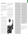
ABSEHEN-SCHNELL-VERSTELLUNG
|
FAST RETICLE ADJUSTMENT
AJUSTEMENT RAPIDE DU RÉTICULE
|
AJUSTE RÁPIDO DE RETÍCULA
REGOLAZIONE RAPIDA DEL RETICOLO
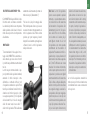
FRA
Fast reticle adjustment
BEDIENUNGSANLEITUNG
|
INSTRUCTION MANUAL
MODE D’EMPLOI
|
MANUAL DE INSTRUCCIONES
ISTRUZIONE D’USO

2 3
DE
WILLKOMMEN
BEI MINOX!
Mit diesem Zubehör aus dem Hause MINOX hast du
dich für ein Produkt von höchster Präzision entschieden.
Diese Anleitung soll dir helfen, das Leistungsspektrum
deiner MINOX FRA Absehen-Schnell-Verstellung optimal
zu nutzen.
Wir wünschen dir viel Freude und jederzeit
eine perfekte Sicht.
Willkommen bei MINOX! ............................................................................. 2
Lerne dein FRA kennen .................................................................................. 4
Lieferumfang .....................................................................................................5
Informationen für deine Sicherheit .......................................................... 6
Montage...............................................................................................................10
Absehenverstellung .......................................................................................12
Wartung und Pflege ........................................................................................ 13
Problembehebung ........................................................................................... 13
Service .................................................................................................................. 14
Gewährleistungsbestimmungen ................................................................ 15
INHALTSVERZEICHNIS

4 5
DE
2
3
5
4
1
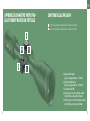
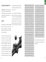
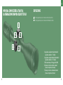
LIEFERUMFANG
Verstellturm für die vertikale Absehen-Korrektur
Verstellturm für die horizontale Absehen-Korrektur
LERNE DEIN FRA KENNEN
DIE ABSEHEN-SCHNELL-VERSTELLUNG
1 | vertikale Schnell-Verstellung
(maximaler Verstellbereich: 5,5 mrad)
2 | horizontale Schnell-Verstellung
(maximaler Verstellbereich: ±2,7 mrad)
3 | Gewindestifte zur Fixierung der FRA
4 | Skala zur vertikalen Korrektur in mrad
(1 Teilstrich entspricht 0,1 mrad)
5 | Skala zur horizontalen Korrektur in mrad
(1 Teilstrich entspricht 0,1 mrad)

6 7
DE
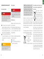
INFORMATIONEN FÜR
DEINE SICHERHEIT
Umwelteinflüsse
GEFAHR!
Schaue keinesfalls mit dem Ziel-
fernrohr in die Sonne oder Laser-
lichtquellen. Dies kann zu schweren
Augenverletzungen führen.
Setze das Gerät nicht ohne Schutzde-
ckel längere Zeit der Sonne aus. Das
Objektiv und das Okular können wie ein
Brennglas wirken und innen liegende
Bauteile, als auch dahinterliegende Ob-
jekte, zerstören.
Nehme an dem Produkt keinesfalls
eigenständig Eingrie vor. Durch das
Auseinanderbauen kann es zu Beschä-
digungen kommen, die nicht durch die
Garantie abgedeckt sind.
VORSICHT!
Vermeide Berührungen der Metallo-
berfläche nach Sonneneinstrahlung
oder Kälte.
Verschluckungsgefahr
GEFAHR!
Lasse Batterien und die abnehmbaren
Außenteile nicht in die Hände von
Kindern geraten (Verschluckungsge-
fahr).
Batterie-Entsorgung
Batterien gehören nicht in den Hausmüll!
Bitte bediene dich bei der Rückgabe ver-
brauchter Batterien eines in deinem Land
evtl. vorhandenen Rücknahmesystems.
Bitte gebe nur entladene Batterien ab.
Batterien sind in der Regel dann entladen,
wenn das damit betriebene Gerät:
abschaltet
nach längerem Gebrauch der Batterie
nicht mehr einwandfrei funktioniert.
Hinweis: Verwende nur vom Hersteller
empfohlene Batterietypen. Behandle
gebrauchte Batterien nach den An-
weisungen des Herstellers. Batterien
dürfen keinesfalls ins Feuer geworfen,
erhitzt, wieder aufgeladen, zerlegt
oder aufgebrochen werden.
Deutschland: Als Verbraucher bist du
gesetzlich dazu verpflichtet, gebrauchte
Batterien zurückzugeben. Du kannst deine
alten Batterien überall dort unentgelt-
lich abgeben, wo die Batterien gekauft
wurden. Ebenso bei den öentlichen
Sammelstellen in deiner Stadt oder Ge-
meinde.
Diese Zeichen findest du auf schadsto-
haltigen Batterien:
Pb = Batterie enthält Blei
Cd = Batterie enthält
Cadmium
Hg = Batterie enthält
Quecksilber
Li = Batterie enthält
Lithium
Benutzerinformationen zur Entsorgung
von elektrischen und elektronischen
Geräten (private Haushalte)
Dieses Symbol auf Produk-
ten und/oder begleitenden
Dokumenten bedeutet, dass
verbrauchte elektrische
und elektronische Produkte
nicht mit gewöhnlichem
Haushaltsabfall vermischt werden sollen.
Bringe zur ordnungsgemäßen Behand-
lung, Rückgewinnung und Recycling
diese Produkte zu den entsprechenden
Sammelstellen, wo sie ohne Gebühren
entgegengenommen werden. In einigen

8 9
DE
Ländern kann es auch möglich sein, diese
Produkte beim Kauf eines entsprechenden
neuen Produkts bei deinem örtlichen Ein-
zelhändler abzugeben. Die ordnungsgemä-
ße Entsorgung dieses Produkts dient dem
Umweltschutz und verhindert mögliche
schädliche Auswirkungen auf Mensch und
Umgebung, die aus einer unsachgemäßen
Handhabung von Abfall entstehen können.
Genauere Informationen zur nächstge-
legenen Sammelstelle erhälst du bei
deiner Gemeindeverwaltung. In Überein-
stimmung mit der Landesgesetzgebung
können für die unsachgemäße Entsorgung
dieser Art von Abfall Strafgebühren erho-
ben werden.
Für Geschäftskunden in der Europäischen
Union
Bitte trete mit deinem Händler oder Liefe-
ranten in Kontakt, wenn du elektrische und
elektronische Geräte entsorgen möchtest.
Er hält weitere Informationen für dich
bereit.
Informationen zur Entsorgung in anderen
Ländern außerhalb der Europäischen
Union
Dieses Symbol ist nur in der Europäischen
Union gültig. Bitte trete mit deiner Ge-
meindeverwaltung oder deinem Händler
in Kontakt, wenn du dieses Produkt ent-
sorgen möchtest, und frage nach einer
Entsorgungsmöglichkeit.
Funktion
Vor dem Arbeiten am an der Wae mon-
tierten Zielfernrohr stets überprüfen
und gewährleisten, dass die Schusswaf-
fe entladen ist.
Zum Schutz vor Verletzungen achte im
montierten Zustand auf ausreichend
Augenabstand.
Bitte vergewissere dich vor der Benut-
zung, dass dein Zielfernrohr einwand-
frei funktioniert.
Prüfe durch Hindurchschauen, ob die
Optik ein klares, ungestörtes Bild liefert.
Bei grober Behandlung ist eine Dejus-
tierung nicht auszuschließen.
Die richtige Einstellung des Absehens
prüfst du durch Kontrollschießen.
Bestimmungsgemäßer Gebrauch
Das MINOX Zielfernrohr dient ausschließ-
lich als Zielhilfe zur Montage auf jagd-
lichen und sportlichen Gewehren. Eine
andere oder darüber hinausgehende Be-
nutzung gilt als nicht bestimmungsgemäß.
Zur bestimmungsgemäßen Verwendung
gehört auch das Einhalten der Hinweise
der Betriebsanleitung in Bezug auf Sicher-
heit, Betrieb, Instandhaltung und Wartung.
Für aus nicht bestimmungsgemäßer
Verwendung resultierende Schäden haf-
tet allein der Benutzer. Dies gilt auch für
eigenmächtige und unsachgemäße Verän-
derungen am Zielfernrohr.

10 11
DE
FAST RETICLE ADJUSTMENT – FRA
Mit der MINOX FRA hast du die Möglich-
keit auch auf größere Distanzen „Fleck“
zu halten. Der Geschossabfall wird hierbei
durch das Verstellen der Visierlinie des
Zielfernrohrs entsprechend der Entfernung
kompensiert.
MONTAGE
Wir empfehlen, die Montage der MINOX
FRA von einer Fachwerkstatt oder einem
Büchsenmacher durchführen zu lassen.
So ist gewährleistet, dass alle Produkte
fachgerecht aufeinander abgestimmt sind.
Die Türme werden montiert indem die
Schutzkappen der Standardverstellungen
abgeschraubt werden, das Zielfernrohr wie
üblich eingeschossen und anschließend
die Standard Verstelltürme durch die FRA
Verstelltürme ersetzt werden. Dazu kann
das dem ZF beiliegende Werkzeug (Sechs-
kantschlüssel SW 1,5) verwendet werden.
Hierbei ist darauf zu achten, dass beim An-
ziehen der Gewindestifte der Indexstrich
der „0“ der FRA Verstelltürme genau auf die
Indexmarkierung am Zielfernrohr ausge-
richtet sind („Nullen“). *
* Sollte nach dem Montieren der FRA ein
abermaliges Einschießen vorgenommen
werden müssen, so kann es erforderlich
sein, die FRA Verstelltürme vorüberge-
hend in einer anderen Position zu mon-
tieren, um die integrierten Endanschläge
überwinden zu können. Danach können
die FRA Verstelltürme wieder in der Null-
position aufgesetzt und fixiert werden.
Hinweis: Die Verstelltürme können
jederzeit mit Hilfe von zwei Gewin-
destiften vom Verstellmechanismus
entkoppelt und anschließend genullt
werden. Beim Nullen der FRA Ver-
stelltürme mit gelösten Schrauben
sind keine Klicks fühl- und hörbar.
Dies zeigt an, dass die Verstelltürme
erfolgreich vom Verstellmechanis-
mus entkoppelt wurden. Um nach
dem Einschießen die Verstelltürme
zu nullen, löse die Gewindestifte
mit dem 1,5 mm Innensechskant-
schlüssel. Eine halbe Umdrehung ist
ausreichend. Die Schrauben sollten
nicht weiter herausgedreht werden.
Drehe nun die Verstelltürme in die
Nullposition. Anschließend ziehst du
die Gewindestifte handfest an. Halte
den Innensechskantschlüssel dabei
am kurzen Schenkel. So verhinderst
du ein zu hohes Drehmoment. Wenn
du beim Verstellen zum Einschießen
den Nullanschlag erreichst (also z.B.
Hochschuss vorliegt, sich der Verstell-
turm aber aufgrund des Nullanschlags
nicht mehr in Richtung „tief“ verstel-
len lässt), dann löse die Gewindestifte
des Turms, drehe diesen mindestens
um den Wert des Hochschusses in
Richtung „hoch“ und ziehe die Gewin-
destifte wieder fest. Nun steht wieder
Verstellbereich zur Verfügung, um
das Absehen entsprechend der Tre-
punktlage zu verstellen. Analog kann
auch mit dem Verstellturm der Seiten-
verstellung verfahren werden. Soll-
test du beim Nullen die Schrauben
versehentlich zu weit herausgedreht
haben, lassen sich die Verstelltürme
vom Zielfernrohr abziehen. Um diese
wieder zu montieren, drücke sie auf
den Verstellmeachnismus des Ziel-
fernrohrs und ziehe anschließend die
Gewindestifte wieder fest.
Die nun übrig gebliebenen Türme der
Standardverstellung aus dem Lieferum-
fang des Zielfernrohrs sollten sicher ver-
wahrt werden.

12 13
DE
ABSEHENVERSTELLUNG
Die Verstelltürme für Höhe und Seite
sind mit hör- und fühlbaren Klickrasten
und Skalenstrichen in 0.1 mrad Schritten
ausgestattet. Ein Klick von 0.1 mrad (Mil-
liradiant, auch „mil“ genannt) entspricht 1
cm/100 m. Die Zahlen der Skala des Hö-
henverstellturms bezeichnen den Hoch-
schuss gegenüber der Nullposition.
Bei der Skala des Seitenverstellturms steht
vor der Zahl jeweils ein „R“ oder „L“. Dies
zeigt die Richtung an, in die sich die Tre-
punktlage bei der jeweiligen Einstellung
verlagert. Soll z.B. Seitenwind von rechts
kompensiert werden, der eine Trepunkt-
verschiebung nach links verursacht, so
muss der Seitenverstellturm um den ent-
sprechenden Wert in Richtung „R“ gedreht
werden. Diese Beschriftung korrespondiert
mit der Ausgabe der meisten Ballistikpro-
gramme, bei denen die Ausgabe der Werte
für die Seitenverstellung mit einem „R“
oder „L“ als Präfix für die Richtung erfolgt.
Die Verstelltürme drehen „CCW“ (coun-
terclockwise, im Gegenuhrzeigersinn). Die
Drehrichtung bezeichnet die Richtung, in
die gedreht werden muss, um eine Tre-
punktlageveränderung in Richtung „hoch“
bzw. „rechts“ zu bewirken.
Der Höhenverstellturm ist mit einem
Nullanschlag (Zero Stop) ausgestattet,
der die Drehbewegung der Stellkappen
begrenzt. Dieser Nullanschlag ist fest ins-
talliert und muss nicht justiert werden. Er
stoppt die Drehbewegung der Höhenver-
stellung einige Klicks unterhalb der Null-
stellung. Der Seitenverstellturm besitzt
einen Anschlag, der den Seitenverstellbe-
reich begrenzt, so dass die Stellkappe nicht
mehr als eine halbe Umdrehung in eine
Richtung gedreht werden kann. Zum Ein-
schießen der Wae drehe die Stellkappen
für Höhe und Seite in die entsprechende
Richtung, bis das Absehen mit dem Zen-
trum der Schussgruppe übereinstimmt.
Bei Hochschuss muss die Stellkappe des
Höhenverstellturms in Richtung „tief“ ver-
stellt werden, bei Rechtsschuss die Stell-
kappe des Seitenverstellturms in Richtung
„links“, bei Abweichungen in die andere
Richtung jeweils umgekehrt.
WARTUNG UND PFLEGE
Die nötige Pflege von Bedienelementen
beschränkt sich auf das Entfernen von
Staub und Schmutz, der die beweglichen
Bedienelemente beeinträchtigen kann.
Staub, Sand und Schmutz können unter
fließendem Wasser abgespült und das
Produkt anschließend mit einem sauberen
Tuch trocken getupft werden.
PROBLEMBEHEBUNG
Probleme mit der Tregenauigkeit
Eine der häufigsten Ursachen für Probleme
mit der Tregenauigkeit (übermäßig große
Gruppen, Veränderungen der Trepunktla-
ge) ist die Zielfernrohrmontage. Überprüfe
den korrekten und festen Sitz der Monta-
geteile. Stelle weiterhin sicher, dass der
Lauf frei ist von Öl, Reinigungsmittel und
übermäßigen Verschmutzungen durch
Schmauch- und Geschossablagerungen.
Verwende nur Munition eines Herstellers
mit der gleichen Losnummer und ver-
wende eine solide Auflage wie z.B. Sand-
säcke. Sollten weiterhin Probleme mit der
Tregenauigkeit bestehen, so wende dich
zur Überprüfung der Wae bitte an eine
Fachwerkstatt.

14 15
DE
SERVICE
Um unnötige Kosten und Verzögerungen
zu vermeiden, lese zuerst alle Anwenderin-
formationen und Problembehebungsvor-
schläge, bevor du dein MINOX Produkt ein-
sendest. Wenn eine Reparatur notwendig
ist, folge diesen Anweisungen, wie du dein
Produkt direkt zum MINOX Kundenservice
oder zu deinem autorisierten MINOX Fach-
händler einschicken kannst.
1. Packe dein MINOX Produkt mit ausrei-
chend Verpackungsmaterial ein, um Be-
schädigungen zu vermeiden.
2. Lege eine detaillierte Beschreibung des
Problems mit einer Kopie des originalen
Kaufbelegs bei.
3. Sende dein Paket an:
In Deutschland:
MINOX GmbH (Werk 2)
Technischer Service
Wilhelm-Loh-Str. 1
35578 Wetzlar
In Großbritannien:
Blaser Sporting Limited
Unit 12
The Pines
Broad Street
Guildford
Surrey
GU3 3BH
In den USA:
Blaser USA
403 East Ramsey, Suite 301
San Antonio, Texas 78216
In allen anderen Ländern schicke dein
MINOX Produkt an den von MINOX au-
torisierten Distributor. Dessen Anschrift
findest du unter: www.minox.com/dealer
GEWÄHRLEISTUNGSBESTIMMUNGEN
Mit dem Kauf dieses MINOX Zubehörs
hast du ein Produkt erworben, das nach
besonders strengen Qualitätsrichtlinien
hergestellt und geprüft wurde. Für dieses
Produkt gilt die gesetzliche Gewährleis-
tung von 2 Jahren gemäß den nachstehen-
den Regelungen ab dem Tag des Verkaufs
durch einen autorisierten Händler:
In der Gewährleistungszeit werden Bean-
standungen, die auf Fabrikationsfehlern
beruhen, kostenlos und nach eigenem
Ermessen durch Instandsetzung, Aus-
tausch defekter Teile oder Umtausch in
ein gleichartiges einwandfreies Erzeug-
nis behoben. Weitergehende Ansprüche,
gleich welcher Art und gleich aus welchem
Rechtsgrund im Zusammenhang mit dieser
Gewährleistung, sind ausgeschlossen.
Gewährleistungsansprüche entfallen,
wenn der betreende Mangel auf unsach-
gemäße Behandlung – wozu auch die Ver-
wendung von Fremdzubehör zählen kann
– zurückzuführen ist, ein Eingri von nicht
autorisierten Personen und Werkstätten
durchgeführt oder die Fabrikationsnum-
mer unkenntlich gemacht wurde.
Gewährleistungsansprüche können nur bei
Vorlage eines maschinengeschriebenen
Kaufbelegs eines autorisierten Händlers
geltend gemacht werden.
Bei Inanspruchnahme der Gewährleistung
leite bitte das MINOX Produkt zusammen
mit dem Original des maschinengeschrie-
benen Kaufbelegs und einer Schilderung
der Beanstandung dem Kundendienst der
MINOX GmbH oder einer Landesvertretung
zu.
Touristen steht im Bedarfsfalle unter
Vorlage des maschinengeschriebenen
Kaufbelegs die Vertretung des jeweiligen
Reiselandes gemäß den Regelungen zur
Gewährleistung der MINOX GmbH zur
Verfügung.

16 17
EN
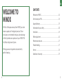
WELCOME TO
MINOX
With this riflescope accessory from MINOX, you have
chosen a product of the highest precision. These
instructions are intended to help you take advantage
of the full performance spectrum of your MINOX FRA
Fast Reticle Adjustment System.
Wishing you much enjoyment and consistently
perfect shooting.
Welcome to MINOX ......................................................................................... 16
Get to know your FRA ..................................................................................... 18
Scope of delivery .............................................................................................. 19
Information for your safety ..........................................................................20
Installation .........................................................................................................24
Reticle adjustment ..........................................................................................26
Maintenance and care ....................................................................................27
Troubleshooting ...............................................................................................27
Service .................................................................................................................. 28
Conditions of warranty ..................................................................................29
CONTENTS

18 19
EN
2
3
5
4
1
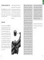
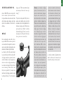
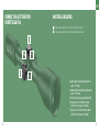
GET TO KNOW YOUR FRA –
FAST RETICLE ADJUSTMENT SYSTEM
SCOPE OF DELIVERY
Elevation adjustment turret
Windage adjustment turret
1 | Elevation fast adjustment turret
(maximum adjustment range: 5.5 mrad)
2 | Windage fast adjustment turret
(maximum adjustment range: ±2.7 mrad)
3 | Threaded pin screws to tighten the FRA
4 | Scale for elevation correction in mrad
(1 graduation mark is equivalent to 0.1 mrad)
5 | Scale for windage correction in mrad
(1 graduation mark is equivalent to 0.1 mrad)

20 21
EN
INFORMATION FOR YOUR SAFETY
Environmental impacts
DANGER!
Never look into the sun or laser light
sources with the riflescope. This can
cause serious eye injury.
Do not expose the unit to sunlight for
long periods without a protective cover.
The lens and eyepiece can act like a
focal lens and destroy internal compo-
nents, as well as objects behind them.
Do not carry out any work on the prod-
uct yourself. Disassembly may result
in damage that is not covered by the
warranty.
WARNING!
Avoid touching the metal surface after
exposure to sunlight or cold.
Choking hazard
DANGER!
Do not let children handle batteries
and removable external parts (chok-
ing hazard).
Battery disposal
Batteries should not be disposed of with
household waste!
When returning used batteries, please use
a collection system that may be available
in your country. Please return only dis-
charged batteries.
Batteries are usually discharged when the
device that uses them:
switches o
does not function properly after pro-
longed use of the battery.
Note: Only use battery types recom-
mended by the manufacturer. Handle
used batteries according to the manu-
facturer‘s instructions. Batteries must
not be thrown into fire or heated,
recharged, disassembled, or broken.
Germany: As a consumer, you are legally
obliged to return used batteries. You can
return your old batteries free of charge an-
ywhere where batteries can be bought. The
same applies to public collection points in
your city or municipality.
The following symbols are found on bat-
teries that contain harmful substances:
Pb = battery contains lead
Cd = battery contains
cadmium
Hg = battery contains
mercury
Li = battery contains lithium
User information on the disposal of elec-
trical and electronic equipment (private
households)
This symbol on products
and/or accompanying docu-
ments means that used elec-
trical and electronic products
should not be mixed with
normal household waste. For
proper treatment, recovery and recycling,
take these products to the appropriate col-
lection points where they will be accepted
free of charge. In some countries you may
be able to return your products to your lo-
cal retailer upon the purchase of an equiv-
alent new product. Proper disposal of this
product will protect the environment and
prevent possible harmful eects on people
and the environment that may result from
improper handling of waste. For more in-
formation on the nearest collection point,
please contact your local municipal oce.
In accordance with national legislation,
penalties may be imposed for the improper
disposal of this type of waste.

22 23
EN
For business customers in the European
Union
Please contact your dealer or supplier if
you wish to dispose of electrical and elec-
tronic equipment. He will provide you with
further information.
Information on disposal in countries
outside the European Union
This symbol is only valid in the European
Union. If you wish to dispose of this prod-
uct, please contact your local municipal
oce or your dealer and inquire about
disposal options.
Function
Before working on the riflescope
mounted on the firearm, always check
and ensure that the firearm is unloaded.
To protect against injury, make sure that
there is sucient eye distance when it
is mounted.
Before using the riflescope, please make
sure that it is working properly.
Check this by looking through it to see
whether the optics provide a clear, un-
disturbed picture.
Misalignment cannot be ruled out in
case of rough handling.
Check the correct adjustment of the
reticle by means of test shooting.
Intended use
The MINOX riflescope serves exclusively as
an aiming aid to be mounted on hunting
and sporting rifles. Any other use or use be-
yond what is specified is deemed to be not
for its intended purpose. Proper use also
includes compliance with the instructions
in the operating manual regarding safety,
operation, maintenance and servicing. The
user is solely liable for damage resulting
from improper use. This also applies to
arbitrary and improper modifications to
the scope.

24 25
EN
FAST RETICLE ADJUSTMENT – FRA
With the MINOX FRA, you can now remain
dialed-in at dead center, even at longer
distances. The sight line of the riflescope
can be adjusted to compensate for bullet
drop at various distances.
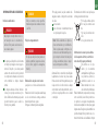
INSTALLATION
We recommend to have the MINOX FRA in-
stalled by a specialized workshop or a gun-
smith. This will ensure that all products are
professionally aligned with each other.
The turrets are mounted by first removing
the factory turrets, zeroing the riflescope
and then installing the FRA turrets instead
of the original ones. For this purpose, you
can use the Allen key (1.5 mm), which was
included in the delivery of your riflescope.
When tightening the pin screws, make sure
that the „0“ index mark on the FRA turret is
exactly aligned with the index mark on the
scope („zeroed“). *
* If after installing the FRA it should be-
come necessary to re-zero your riflescope,
it may be necessary to temporarily loosen
and retighten the FRA turrets at a dier-
ent position to bypass the integrated end
stops. After re-zeroing, the FRA turrets can
be set and tightened at the „zero“ index
marks again.
Note: Using the two pin screws, the
turret knobs can be loosened from
the tower at any time and then zeroed
again. When zeroing the FRA turrets
after the screws have been loosened,
no clicks can be felt or heard. This
is an indication that the knobs have
been successfully decoupled from the
adjustment tower. To zero the turrets
after shooting, loosen the screw pins
with the 1.5 mm Allen key. Half a turn
is sucient. The screws should not
be unscrewed any further than this.
Now turn the knobs to the “zero” in-
dex mark and then tighten the screws
hand-tight. Hold the Allen key by the
short leg to prevent exerting too
much torque. If you have reached the
zero-stop while zeroing your rifle-
scope (e.g. your shot is too high, but
the turret cannot be adjusted down-
wards due to the zero-stop), loosen
the pin screws, turn the knob at least
by the value to compensate for your
high shot and tighten the screws
again. You will now have enough
adjustment range available to adjust
the reticle to the point of impact. The
same procedure can be done with the
windage tower. If you have accidental-
ly unscrewed the screws too far while
zeroing your scope, the knobs can be
removed from the scope. To remount
them, press them onto the towers and
then tighten the screws again.
The standard turrets included in the deliv-
ery of your riflescope should now be stored
in a safe place.

26 27
EN
RETICLE ADJUSTMENT
The elevation and windage adjustment
turrets are equipped with audible and tac-
tile click stops and 0.1 mrad scale marks.
A click of 0.1 mrad (Milliradian, also called
„mil“) corresponds to 1 cm/100 m. The
numbers on the elevation turret indicate
the value of bullet drop compensation in
relation to the zero position.
The numbers on the windage tower are
preceded by an „R“ or „L“. This indicates
the direction in which the trajectory curve
should be shifted in accordance with the
respective setting. If, for example you need
to compensate for a crosswind from the
right, which would cause a point of impact
displacement to the left, the windage tow-
er must be rotated by the corresponding
value in the „R“ direction. This lettering
corresponds to the output of most ballistic
calculators, where the output values for
windage adjustments are indicated with
an „R“ or „L“ prefix for the direction in which
to turn the turret. The adjustment towers
turn „CCW“ (counterclockwise).
The direction of rotation denotes the
direction in which you have to turn the
knob to change the point of impact „up“
ie. „right“. The elevation tower is equipped
with a zero-stop, which limits the rotation
of the adjustment knobs. This zero-stop is
permanent and does not need to be ad-
justed. It prevents an “over turning” of the
elevation adjustment a few clicks below
the zero position. The windage tower has a
stop that limits the windage compensation
range, so that the adjustment knob cannot
be turned more than half a turn in one di-
rection. To zero the rifle, turn the windage
and elevation towers in the corresponding
direction until the reticle coincides with
the center of the shot group. For high
shots, the elevation turret must be adjust-
ed in the „low“ direction. For shots too far
to the right, the windage knob must be
adjusted in the „left“ („L“) direction. For
deviations in the other directions in each
case, apply the opposite steps.
MAINTENANCE AND CARE
The necessary care of the towers is limited
to the removal of dust and dirt that can
aect the moving elements. Dust, sand and
dirt can be rinsed o under running water
and the product can then be dabbed dry
with a clean cloth.
TROUBLESHOOTING
One of the most common causes for inac-
curacy (excessively large groups, double
groups, stringing or flyers) is caused by
improper mounting of the riflescope. Check
all mounting components for tightness.
Furthermore, make sure that the barrel is
free of oil, cleaning agents and excessive
fouling by powder residue and projectile
debris. Use ammunition from the same
manufacturer and lot number, and place
the weapon on a solid surface such as a
sandbag. If accuracy problems should per-
sist, please contact a qualified gunsmith to
have your weapon examined.

28 29
EN
SERVICE
To avoid unnecessary expenses and delays,
read through all of the user information
and troubleshooting suggestions before
sending in your MINOX product. If service
is required, follow these instructions on
how to send your product directly to the
MINOX service center or to your authorized
MINOX dealer.
1. Pack your MINOX product with adequate
packing materials to prevent damage.
2. Enclose a detailed description of the
problems and include a copy of the orig-
inal proof of purchase.
3. Ship your package to:
In Germany:
MINOX GmbH (Werk 2)
Technischer Service
Wilhelm-Loh-Str. 1
35578 Wetzlar
In Great Britain:
Blaser Sporting Limited
Unit 12
The Pines
Broad Street
Guildford
Surrey
GU3 3BH
In the USA:
Blaser USA
403 East Ramsey, Suite 301
San Antonio, Texas 78216
In all other countries, send your MINOX
product to your authorized MINOX distrib-
utor. Their addresses can be found at: www.
minox.com/dealer
CONDITIONS OF WARRANTY
With the purchase of this MINOX accessory,
you have acquired a product that has been
manufactured and inspected in accordance
with especially high quality standards. For
this product, we provide a legal warranty
of 2 years in accordance with the following
regulations from the day of purchase at an
authorized dealer:
During the warranty period we shall
compensate complaints based on faulty
manufacture with repair, replacement of
defective parts or by replacement with an
identical flawless product at our own dis-
cretion. Consequential claims, regardless
of manner or legal argument in connection
with this warranty, will not be accepted.
Claims under warranty are null and void
if the defect has been caused by improp-
er handling – which also can include the
combined use of non-MINOX accessories
– if the MINOX product is serviced by un-
authorized persons or workshops, or if the
serial number has been made unreadable.
Warranty claims can only be made by sub-
mission of the printed receipt as proof of
purchase from an authorized dealer.
When submitting claims under warranty,
please return the MINOX product together
with the proof of purchase and a descrip-
tion of the complaint to the MINOX service
center in Germany, or the nearest MINOX
dealer.
Tourists may, if necessary, make use of the
MINOX dealer in the country in which they
are travelling (within the warranty terms
of MINOX GmbH) by presenting the printed
proof of purchase.

30 31
FR
BIENVENUE
CHEZ MINOX
Avec cet accessoire de lunette de visée de la marque
MINOX, vous avez choisi un produit de la plus haute
précision. Ces instructions sont destinées à vous aider
à utiliser de manière optimale le spectre des perfor-
mances de votre système de réglage rapide de réticule
MINOX FRA.
Nous vous souhaitons beaucoup de plaisir et une vue
parfaite à tout moment.
Bienvenue chez MINOX ................................................................................ 30
Apprenez à connaître votre FRA ...............................................................32
Contenu de la livraison ................................................................................33
Informations pour votre sécurité ..............................................................34
Montage...............................................................................................................38
Réglage du réticule ........................................................................................40
Maintenance et entretien ............................................................................41
Élimination des dysfonctionnements ..................................................... 41
Maintenance ......................................................................................................42
Conditions de garantie .................................................................................. 43
TABLE DES MATIÈRES

32 33
FR
2
3
5
4
1
APPRENEZ À CONNAÎTRE VOTRE FRA –
L‘AJUSTEMENT RAPIDE DU RÉTICULE
CONTENU DE LA LIVRAISON
Tourelle de réglage pour l‘ajustement de l‘élévation du réticule
Tourelle de réglage pour l‘ajustement de la dérive du réticule
1 | réglage vertical rapide
(plage de réglage maximale : 5,5 mrad)
2 | réglage horizontal rapide
(plage de réglage maximale : ±2,7 mrad)
3 | vis de fixation du FRA
4 | échelle pour la correction verticale en mrad
(1 trait d‘échelle correspond à 0,1 mrad)
5 | échelle pour la correction horizontale en mrad
(1 trait d‘échelle correspond à 0,1 mrad)

34 35
FR
INFORMATIONS POUR VOTRE
SÉCURITÉ
Influences de l’environnement
DANGER !
Pour éviter des lésions oculaires
graves, ne regardez en aucun cas le
soleil ou des sources de lumière avec
la lunette de visée.
N’exposez pas au soleil l’appareil sans
le couvercle de protection et durant une
période prolongée. L’objectif et l’ocu-
laire peuvent agir comme un verre brû-
lant et détruire les parties intérieures,
mais aussi des objets n’apparaissant
pas directement.
N’essayez jamais de réparer le produit
vous-même. Le démontage peut en-
dommager l’appareil. Les dommages
éventuels ne sont alors pas couverts
par la garantie.
ATTENTION !
Évitez de toucher la surface métal-
lique après qu’elle a été exposée aux
rayons du soleil ou au froid.
Risque d‘ingestion
DANGER !
Gardez les piles et les parties exté-
rieures détachables hors de portée
des enfants (risque d‘ingestion).
Mise au rebut des piles
Les piles ne doivent pas être jetées avec
les déchets ménagers !
Lorsque vous jetez les piles usagées, uti-
lisez l’un des systèmes de récupération
pouvant exister dans votre pays.
Donnez uniquement des piles déchargées.
Les piles sont généralement déchargées
quand :
l’appareil utilisé ne
fonctionne plus correctement après une
longue période d’arrêt.
Remarque : Utilisez uniquement les
types de piles recommandés par le
fabricant. Utilisez les piles usagées en
respectant les consignes du fabricant.
Les piles ne doivent en aucun cas être
jetées au feu, chauées, rechargées,
désassemblées ou ouvertes.
Remarque destinée à l’Allemagne : La lé-
gislation allemande vous oblige, en tant
que consommateur, à redonner les piles
usagées. Vous pouvez redonner vos an-
ciennes piles à n’importe quel endroit et
gratuitement où elles ont été achetées. Il
est également possible de les déposer dans
les points de collecte publics de votre ville
ou commune.
Vous trouverez les indications suivantes sur
les piles contenant des substances nocives :
Pb = La pile contient
du plomb
Cd = La pile contient
du cadmium
Hg = La pile contient
du mercure
Li = La pile contient
du lithium
Informations destinées à l’utilisateur
concernant la mise au rebut des appareils
électriques et électroniques (ménages)
Ce symbole figurant sur
les produits et/ou sur les
documents joints signifie
que les produits électriques
et électroniques consom-
més ne doivent pas être
mélangés aux déchets
ménagers habituels. Apportez gratuitement
ces produits pour traitement, récupération
et recyclage aux points de collecte corres-
pondants. Dans certains pays, ces produits
peuvent être éventuellement déposés
chez votre détaillant lors de l’achat d‘un

36 37
FR
nouveau produit correspondant. La mise
au rebut appropriée de ce produit permet
de protéger l’environnement et empêche
d’éventuelles conséquences nuisibles sur
l’Homme et son environnement liées à une
gestion inappropriée des déchets. Vous
trouverez auprès de votre municipalité des
informations plus précises sur le point de
collecte le plus proche. Conformément à la
législation du pays, des amendes peuvent
être dressées si les déchets n’ont pas été
jetés conformément aux éléments indiqués
ci-dessus.
Pour les professionnels exerçant dans
l’Union Européenne
Veuillez contacter votre revendeur ou four-
nisseur si vous souhaitez jeter des appareils
électriques et électroniques. Votre reven-
deur ou fournisseur vous donnera de plus
amples informations.
Informations sur la mise au rebut dans
des pays situés en dehors de l’Union
Européenne
Ce symbole est valable uniquement dans
l’Union Européenne. Veuillez contacter
votre municipalité ou votre revendeur si
vous souhaitez jeter ce produit. Demandez
également des informations sur la méthode
de mise au rebut à utiliser.
Fonctionnement
Avant de manipuler la lunette de visée
montée sur l’arme, contrôlez et vérifiez
systématiquement que l’arme à feu est
déchargée.
Pour éviter toute blessure, veillez à ce
que vos yeux soient à une distance suf-
fisante de l’appareil lorsqu’il est monté.
N’oubliez pas qu’avant utilisation, votre
lunette de visée doit fonctionner parfai-
tement.
Regardez à travers l’objectif pour contrô-
ler qu’il fournit une image claire et sans
distorsions.
L’appareil peut être désajusté en cas de
manipulation brusque.
Un tir de contrôle permet de vérifier que
le réticule est correctement réglé.
Utilisation conforme à l’usage prévu
La lunette de visée MINOX sert uniquement
d’aide à la pose de fusils utilisés pour la
chasse et des activités sportives. Une utili-
sation autre ou dépassant ce cadre n’est pas
considérée comme conforme à la finalité
du produit. L’utilisation conforme englobe
aussi le respect des consignes de sécurité,
d’utilisation, d’entretien et de maintenance.
La responsabilité juridique liée à des
dommages causés par une utilisation non
conforme à l’usage prévu relève unique-
ment de l’utilisateur. Cette responsabilité
s’applique également aux modifications
non-conformes et réalisées volontairement
sur la lunette de visée.

38 39
FR
FAST RETICLE ADJUSTMENT – FRA
Avec le MINOX FRA, vous avez la possibi-
lité de continuer à „faire mouche“ même
à longue distance. La descente de la balle
est compensée par le réglage de la ligne
de visée de la lunette en fonction de la
distance.
MONTAGE
Nous recommandons de confier le mon-
tage du MINOX FRA à un atelier spécialisé
ou à un armurier. Cela permet de s‘assurer
que tous les produits sont adaptés les uns
aux autres de manière professionnelle.
Les tourelles sont montées en dévissant
les capuchons de protection des dispositifs
de réglage standard, en plaçant la lunette
comme d‘habitude et en remplaçant en-
suite les tourelles de réglage standard par
les tourelles de réglage FRA. L‘outil fourni
avec la lunette peut être utilisé à cette
fin (clé à six pans SW 1,5). Lorsque vous
serrez les vis de réglage, assurez-vous que
la marque d‘index du „0“ des tourelles de
réglage de la FRA est exactement alignée
avec la marque d‘index de la lunette („zé-
rotage“). *
*Si après le montage de la FRA, il est né-
cessaire de le remettre à zéro, il peut être
nécessaire de monter temporairement les
tourelles de réglage de la FRA dans une
autre position pour franchir les butées
d‘extrémité intégrées. Ensuite, les tourelles
de réglage de la FRA peuvent être repla-
cées en position zéro et être fixées.
Remarque : Les tourelles de réglage
peuvent, à tout moment, être décou-
plées du mécanisme de réglage au
moyen de deux vis sans tête, et en-
suite remises à zéro. Lors de la remise
à zéro des tourelles de réglage de la
FRA avec les vis desserrées, aucun clic
ne peut être ressenti ou entendu. Cela
indique que les tourelles de réglage
ont été découplées avec succès du
mécanisme de réglage. Pour remettre
à zéro les tourelles de réglage après
le tir, il faut desserrer les vis sans tête
à l‘aide de la clé à six pans de 1,5
mm. Un demi-tour sut. Les vis ne
doivent pas être desserrées davan-
tage. Tournez maintenant les tourelles
de réglage jusqu‘à la position zéro.
Puis serrez à la main les vis sans tête.
Tenez la clé à six pans par la branche
la plus courte. De cette manière, vous
évitez un couple trop important. Si,
lors du réglage du tir, vous atteignez
la butée zéro (par exemple, il y a un
tir haut, mais la tourelle ne peut plus
être réglée dans la direction „bas“
à cause de la butée zéro), alors des-
serrez les vis sans tête de la tourelle,
faites-la tourner au moins de la valeur
du tir haut dans la direction „ haut
„ et resserrez les vis sans tête. Vous
pouvez maintenant réutiliser la plage
de réglage pour régler le réticule
en fonction de la position du point
d’impact. La même chose peut être
faite avec la tourelle de réglage de
la dérive latérale. Si vous avez acci-
dentellement dévissé les vis trop loin
lors de la remise à zéro, les tourelles
de réglage peuvent être retirées de
la lunette de visée. Pour les remonter,
appuyez sur le mécanisme de réglage
de la lunette de visée, puis resserrez
les vis sans tête.
Les tourelles restant de l‘ajustement stan-
dard de la livraison de la lunette de visée
doivent être stockées en toute sécurité.
La pagina si sta caricando...
La pagina si sta caricando...
La pagina si sta caricando...
La pagina si sta caricando...
La pagina si sta caricando...
La pagina si sta caricando...
La pagina si sta caricando...
La pagina si sta caricando...
La pagina si sta caricando...
La pagina si sta caricando...
La pagina si sta caricando...
La pagina si sta caricando...
La pagina si sta caricando...
La pagina si sta caricando...
La pagina si sta caricando...
La pagina si sta caricando...
La pagina si sta caricando...
-
 1
1
-
 2
2
-
 3
3
-
 4
4
-
 5
5
-
 6
6
-
 7
7
-
 8
8
-
 9
9
-
 10
10
-
 11
11
-
 12
12
-
 13
13
-
 14
14
-
 15
15
-
 16
16
-
 17
17
-
 18
18
-
 19
19
-
 20
20
-
 21
21
-
 22
22
-
 23
23
-
 24
24
-
 25
25
-
 26
26
-
 27
27
-
 28
28
-
 29
29
-
 30
30
-
 31
31
-
 32
32
-
 33
33
-
 34
34
-
 35
35
-
 36
36
-
 37
37


