ProLights PIXIEBEAM Manuale utente
- Categoria
- Stroboscopi
- Tipo
- Manuale utente

USER MANUAL
MANUALE UTENTE
PIXIE BEAM
BEAM MOVING HEAD
EN - IT

All rights reserved by Music & Lights S.r.l. No part of this instruction manual may be
reproduced in any form or by any means for any commercial use.
In order to improve the quality of products, Music&Lights S.r.l. reserves the right to modify the
characteristics stated in this instruction manual at any time and without prior notice.
All revisions and updates are available in the ‘manuals’ section on site www.musiclights.it
REV.003-03/18

1
PIXIE BEAM
Packing content
• PIXIE BEAM
• Mount bracket
• Power supply cable and signal cable
• Safety rope
• User manual
TABLE OF CONTENTS
Safety
General instructions
Warnings and installation precautions
1 Introduction
1. 1 Description
1. 2 Technical specications
1. 3 Operating elements and connections
2 Installation
2. 1 Mounting
3 Functions and settings
3. 1 Operation
3. 2 Basic
3. 3 Menu structure
3. 4 Slave Receive mode
3. 5 Operation in automatic mode
3. 6 Music mode
3. 7 Sensitivity microphone
3. 8 Linking
3. 9 DMX mode
3. 10 DMX conguration
3. 11 DMX addressing
3. 12 Connection of the DMX line
3. 13 Construction of the DMX termination
3. 14 DMX control
3. 15 Fixture settings
3. 16 Lamp settings
3. 17 Display settings
3. 18 Fixture information
3. 19 Reset functions
3. 20 Special functions
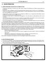
4 Maintenance
4. 1 Maintenance and cleaning the unit
4. 2 Fuse replacement
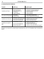
4. 3 Trouble shooting
2
2
3
3
5
6
7
7
8
9
9
9
9
10
10
10
10
12
12
13
16
16
16
17
17
17
19
19
20

PIXIE BEAM
2
WARNING! Before carrying out any operations with the unit, carefully read this instruction
manual and keep it with cure for future reference. It contains important information about
the installation, usage and maintenance of the unit.
SAFETY
General instruction
• The products referred to in this manual conform to the European Community Directives and are there-
fore marked with .
• The unit is supplied with hazardous network voltage (230V~). Leave servicing to skilled personnel only.
Never make any modications on the unit not described in this instruction manual, otherwise you will
risk an electric shock.
• Connection must be made to a power supply system tted with ecient earthing (Class I appliance ac-
cording to standard EN 60598-1). It is, moreover, recommended to protect the supply lines of the units
from indirect contact and/or shorting to earth by using appropriately sized residual current devices.
• The connection to the main network of electric distribution must be carried out by a qualied electrical
installer. Check that the main frequency and voltage correspond to those for which the unit is designed
as given on the electrical data label.
• This unit is not for home use, only professional applications.
• Never use the xture under the following conditions:
- in places wet;
- in places subject to vibrations or bumps;
- in places with an ambient temperature of over 45°C.
• Make certain that no inammable liquids, water or metal objects enter the xture.
• Do not dismantle or modify the xture.
• All work must always be carried out by qualied technical personnel. Contact the nearest sales point for
an inspection or contact the manufacturer directly.
• If the unit is to be put out of operation denitively, take it to a local recycling
plant for a disposal which is not harmful to the environment.
Warnings and installation precautions
• If this device will be operated in any way dierent to the one described in this manual, it may suer
damage and the guarantee becomes void. Furthermore, any other operation may lead to dangers like
short circuit, burns, electric shock, etc.
• Before starting any maintenance work or cleaning the projector, cut o power from the main supply.
• Always additionally secure the projector with the safety rope. When carrying out any work, always com-
ply scrupulously with all the regulations (particularly regarding safety) currently in force in the country
in which the xture’s being used.
• For inside use only. Not designed for outside use.
• The minimum distance between the xture and surrounding walls must be more than 50 cm and the
air vents at the housing must not be covered in any case.
• Install the xture in a well ventilated place.
• Keep any inammable material at a safe distance from the xture.
• The maximum temperature that can be reached on the external surface of the tting, in a thermally
steady state, is high. After power o, please cool down over 15 minutes.
• Shields, lenses or ultraviolet screens shall be changed if they have become damaged to such an extent
that their eectiveness is impaired.
• The lamp (LED) shall be changed if it has become damaged or thermally deformed.
• Never look directly at the light beam. Please note that fast changes in lighting, e. g. ashing light, may
trigger epileptic seizures in photosensitive persons or persons with epilepsy.

3
PIXIE BEAM
- 1 - INTRODUCTION
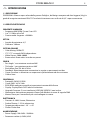
1.1 DESCRIPTION
PIXIEBEAM is a fast, bright and compact moving LED beam luminaire. Some looks are all about scale, and
the Pixiebeam takes this idea to a dierent level featuring incredible speed and innite rotation of both
pan and tilt.
1.2 TECHNICAL SPECIFICATIONS
LIGHT SOURCE
• Source: 60W RGBW Osram Ostar LED
• Lux: 11120lux @3m Full
• Source Life Expectancy: >50.000 h
OPTICS
• Beam Angle: 4,5°
• Lens Diameter: 100mm
COLOR SYSTEM
• Color Mixing: RGBW/FC
• CTC: CTC control through independent DMX channel
• White Presets: 2000~8000K
• Color Wheel: Virtual color wheel with presets
BODY
• Pan Angle: with 360° continuous rotation
• Tilt Angle: with 360° continuous rotation
• Pan/Tilt Resolution: 8/16 bit
• Feedback: Automatic repositioning after accidental movement
• Body: Aluminium structure with hi-resistance polycarbonate cover
• Body Color: Black
CONTROL
• Protocols: DMX512, RDM
• DMX Channels: 16/14/18ch
• RDM: RDM ready for xture remote monitor and settings
• Display: Black OLED high resolution display
• Firmware Upgrade: Yes, via USB-DMX interface (UPBOX1) not included
• Hibernation: Power Safe Mode when lost DMX
• Master/Slave: for synchronized operation of more units linked in a chain
ELECTRONICS
• Dimmer: Linear 0~100% electronic dimmer
• Strobe/Shutter: 1-25 Hz, electronic
• Operating Temperature: -10° ~ +45°
• Flicker: Flicker free operation

PIXIE BEAM
4
ELECTRICAL
• Power Supply: 100-240V – 50/60Hz
• Power Consumption (at 230V): 82W
• Power Consumption (at 120V): 82W
• Output (at 230V): 15 units on a single power line
PHYSICAL
• Cooling: Forced air with low noise fan
• Suspension And Fixing: Any position with “quick-lock” omega brackets
• Signal Connection: 5p in/out
• Power Connection: PowerCON in/out
• IP: 20
• Dimensions (WxHxD): 208x302x144mm
• Weight: 4kg
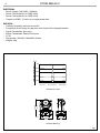
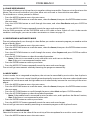
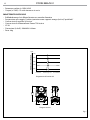
Photometric data
Illuminance at a Distance
4,5°
0m
2.5m
3.0m
5.0m
7.5m
0.35m
0.45m
0.75m
Lux Center Beam Angle: 4,5° Beam Width
11120lx
15850lx
4000lx
1.05m1803lx
Technical drawing
302mm
11,89in
144mm
5,67in
208mm
8,19in
Fig.1

5
PIXIE BEAM
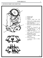
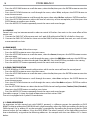
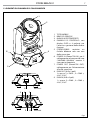
1.3 OPERATING ELEMENTS AND CONNECTIONS
1
2
B
A
3
5 6 7
4
9 8
1. MOVING HEAD
2. ROTARY ARM
3. HANDLE
4. CONTROL PANEL with OLED
display and 4 button used to
access the control panel functions
and manage them.
5. MAIN FUSE HOLDER: replace a
burnt-out fuse by one of the same
type only.
6. POWER IN (PowerCON IN):
for connection to a socket
(100-240V~/50-60Hz) via the
supplied mains cable.
7. POWER OUT (PowerCON OUT):
power output for connection of
multiple units in series.
8. DMX OUT (5-pole XLR):
1 = ground, 2 = DMX-, 3 = DMX+,
4 N/C, 5 N/C
9. DMX IN (5-pole XLR):
1 = ground, 2 = DMX-, 3 = DMX+,
4 N/C, 5 N/C.
Fig.2
View A
View B

PIXIE BEAM
6
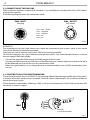
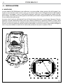
Fig.3
108
OMEGA
BRACKETS
- 2 - INSTALLATION
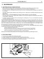
2.1 MOUNTING
The PIXIE BEAM may be set up on a solid and even surface. By means of the xing facilities of the baseplate,
the unit can also be mounted upside down to a cross arm. The base plate is shown in g.3. For xing, stable
mounting clips are required. According to the gure, the bolts of the brackets are placed into the openings
provided in the base plate and turned clockwise until they lock (to the stop). Always ensure that the unit
is rmly xed to avoid vibration and slipping while operating. The mounting place must be of sucient
stability and be able to support a weight of 10 times of the unit’s weight. When carrying out any installa-
tion, always comply scrupulously with all the regulations (particularly regarding safety) currently in force
in the country in which the xture’s being used. Always additionally secure the projector with the safety
rope from falling down. For this purpose, fasten the safety rope at a suitable position so that the maximum
fall of the projector will be 20 cm.

7
PIXIE BEAM
- 3 - FUNCTIONS AND SETTINGS
3.1 OPERATION
Connect the supplied main cable to a socket (100-240V~/50-60Hz). Switch on the PIXIE BEAM with the
power switch. The unit will run built-in program to reset all motors to their home position. Shortly after
that the PIXIE BEAM is ready for operation. After operation, switch o the unit with the power switch.
Disconnect the mains plug from the socket.
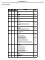
3.2 BASIC
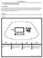
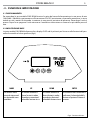
The PIXIE BEAM has a OLED display and 4 button used to access the control panel functions and manage
them (g.4).
Fig.4 - Functions of the buttons
MODE UP DOWN ENTER
Used to access the menu or
to return a previous menu
option
Navigates downwards through
the menu list and increases
the numeric value when in a
function
Navigates upwards through
the menu list and decreases
the numeric value when in
a function
Used to select and store the
current menu or conrm the
current function value or
option within a menu

PIXIE BEAM
8
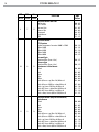
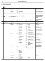
3.3 MENU STRUCTURE
MENU
1 Connect
ð
DMX Address
ð
Value (1-512) DMX address setting
Slave Rece
ð
Choose Slave mode
Sequence
ð
Alone/Master Choose Sequence mode
Music
ð
Alone/Master Choose Sound mode
2 Light
ð
Max Temperature
ð
Value 80~139° C/
176~282° F (85°C)
Lamp o if temperature
continuously over for 5
minutes
Lamp Adjust
ð
Pan, ... ,
ð
Value (000-255)
Adjust value of each
channels
3 Information
ð
Lamp Temp Temperature of driver
4 Set
ð
Reset
ð
All Reset
Movement
ð
Pan Reverse
ð
ON/OFF Pan Reverse
Tilt Reverse
ð
ON/OFF Tilt Reverse
Pan Degree
ð
540/630 Choose Pan Degree
Encoders
ð
ON/OFF Encoder wheel on/o
Move Mode
ð
Standard/Smooth Choose pan/tilt mode
Continuos
ð
Standard/Shortest
UI Set
ð
Mic Sens.
ð
Value (00-99%) Sensitivity of Mic
No Signal
ð
Close/Hold/Auto/Music Mode when no signal
Temperature C/F
ð
Fahrenheit /Celsius
Fans Mode
ð
Auto Speed/High Speed Fans mode
Hibernation
ð
OFF/Min (01-99) Sleeping mode
Backlight
ð
Always On/Min (02-99) Show backlight time
Flip Display
ð
ON/OFF Display 180°reverse
User Mode
ð
Standard/ Basic/
Extended
Users mode
Calibration
ð
Password
ð
050
Insert to unlock the
following settings
Pan
ð
Value (-128-127) Calibrate channel value
... ... ...
Fixture ID
Name
Rdm Mode
-Password-
PID Code
Software Ver. V1.2.00 IC Version
Reload Def
ð
Basic Reload
---Password---
All Reload
ON/OFF

9
PIXIE BEAM
3.4 SLAVE RECEIVE MODE
This mode will allow you to link up the units together without a controller. Choose a unit to function as the
Master. The unit must be the rst unit in line; other units will work as slave with the same eect.
To set the drive as a slave, proceed as follows:
• Press the MODE button to access the main menu.
• Press the UP/DOWN button to scroll the menu, select the Connect, then press the ENTER button to enter
the next menu.
• Press the UP/DOWN button to scroll through the menu, and select Slave Receive and press ENTER to
conrm.
• Press the MODE/ESC button repeatedly to exit the menu and save changes.
Use the DMX connectors of the PIXIE BEAM and an XLR cable to form a chain of units. Under certain
conditions and lengths you want to make a termination as shown on page 13.
3.5 OPERATIONS IN AUTOMATIC MODE
The unit independently runs through its show. Before you send an automatic program you need to set the
drive as Master/Alone:
• Press the MODE button to access the main menu.
• Press the UP/DOWN button to scroll the menu, select the Connect, then press the ENTER button to enter
the next menu.
• Press the UP/DOWN button to scroll through the menu, select Sequence and press ENTER to conrm
your choice.
• Press the UP/DOWN button to select the mode of operation:
- Master, if the unit is connected in series with other units and it acts as the Master;
- Alone, if the unit is not connected to other units.
• Press the ENTER button to conrm your choice.
• Press the MODE/ESC button repeatedly to exit the menu and save changes.
The unit will go into automatic mode by executing the program automatically.
3.6 MUSIC MODE
In music mode, via its integrated microphone, the unit can be controlled by music with a clear rhythm in
the bass range. If the music control should not work optimally, increase the volume or reduce the distance
between the sound source and the light eect unit or alternatively increase the sensitivity of the micro-
phone.
• Press the MODE button to access the main menu.
• Press the UP/DOWN button to scroll the menu, select the Connect, then press the ENTER button to enter
the next menu.
• Press the UP/DOWN button to scroll through the menu, select Music and press ENTER to conrm.
• Press the UP/DOWN button to select the mode of operation:
- Master, if the mobile head is connected in series to other units, and it performs the Master function;
- Alone, if the xture is not connected to other units.
• Press the ENTER button to conrm your choice.
• Press the MODE/ESC button repeatedly to exit the menu and save changes.
The unit will go into music mode by executing an automatic program to the rhythm of music.
3.7 SENSITIVITY MICROPHONE
Select this function to set the value of the sensitivity of the microphone for use with a music control:
• Press the MODE button to access the main menu.

PIXIE BEAM
10
• Press the UP/DOWN button to scroll the menu, select the Set, then press the ENTER button to enter the
next menu.
• Press the UP/DOWN button to scroll through the menu, select UI Set, and press the ENTER button to
enter the next menu.
• Press the UP/DOWN button to scroll through the menu, then select Mic Sens. and press ENTER to conrm.
• Press the UP/DOWN button to adjust the level of sensitivity of the microphone, and then press the
ENTER button to conrm your choice.
• Press the MODE/ESC button repeatedly to exit the menu and save changes.
3.8 LINKING
Several units may be interconnected in order to control all further slave units to the same eect of the
master unit.
1. Connect the DMX OUT of the master unit via 5-pole XLR cable to the DMX IN of the rst slave unit.
2. Connect the DMX OUT of the rst slave unit to the DMX IN of the second slave unit, etc. until all units
are connected in a chain.
3.9 DMX MODE
To enter the DMX mode, follow these steps:
• Press the MODE button to access the main menu.
• Press the UP/DOWN button to scroll the menu, select the Connect, then press the ENTER button to enter
the next menu.
• Press the UP/DOWN button to scroll through the menu, select the DMX Address and press the ENTER key.
• Press the arrow keys to select the desired value (001-512). Press the ENTER key to conrm the setting.
• Press the MODE/ESC button repeatedly to exit the menu and save changes.
3.10 DMX CONFIGURATION
The PIXIE BEAM has 3 DMX channel congurations which can be accessed from the control panel.
• Press the MODE button to access the main menu.
• Press the UP/DOWN button to scroll the menu, select the Set, then press the ENTER button to enter the
next menu.
• Press the UP/DOWN button to scroll through the menu, select Users and press the ENTER button to
enter the next menu.
• Press the UP/DOWN button to scroll through the menu, select User Mode and press ENTER to conrm
your choice.
• Use the UP/DOWN button to select the desired DMX channel conguration (Standard, Basic1, Extended),
then press the ENTER button to conrm your choice.
• Press the MODE/ESC button repeatedly to exit the menu and save changes.
The tables on page 13 show the mode of operation and their values DMX.
The unit is equipped with 5-pole XLR connections.
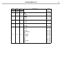
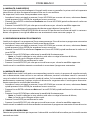
3.11 DMX ADDRESSING
For operation via light control unit with DMX512 protocol, is sucient connect the controller to PIXIE
BEAM. To able to operate the PIXIE BEAM with a light controller, adjust the DMX start address for the rst a
DMX channel. If e. g. address 33 on the controller is provided for controlling the function of the rst DMX
channel, adjust the start address 33 on the PIXIE BEAM. The other functions of the light eect panel are
then automatically assigned to the following addresses. An example with the start address 33 is shown
below:

11
PIXIE BEAM
DMX Address: 75DMX Address: 47DMX Address: 33 DMX Address: 61
Fig.5 - Example 14 DMX channels conguration
. . . . . . . . . . . .
DMX512 Controller
Numero
canali DMX
Indirizzo di
start (esempio)
Indirizzo DMX
occupati
Prossimo indirizzo di start
possibile per unità n°1
Prossimo indirizzo di start
possibile per unità n°2
Prossimo indirizzo di start
possibile per unità n°3
16 33 33-48 49 65 81
14 33 33-46 47 61 75
18 33 33-50 51 67 83

PIXIE BEAM
12
Fig.6
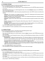
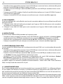
3.12 CONNECTION OF THE DMX LINE
DMX connection employs standard XLR connectors. Use shielded pair-twisted cables with 120Ω imped-
ance and low capacity.
The following diagram shows the connection mode:
ATTENTION
The screened parts of the cable (sleeve) must never be connected to the system’s earth, as this would
cause faulty xture and controller operation.
Over long runs can be necessary to insert a DMX level matching amplier.
For those connections the use of balanced microphone cable is not recommended because it cannot
transmit control DMX data reliably.
• Connect the controller DMX input to the DMX output of the rst unit.
• Connect the DMX output to the DMX input of the following unit. Connect again the output to the input
of the following unit until all the units are connected in chain.
• When the signal cable has to run longer distance is recommended to insert a DMX termination on the
last unit.
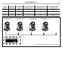
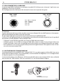
3.13 CONSTRUCTION OF THE DMX TERMINATION
The termination avoids the risk of DMX 512 signals being reected back along the cable when they reach-
es the end of the line: under certain conditions and with certain cable lengths, this could cause them to
cancel the original signals.
The termination is prepared by soldering a 120Ω 1/4 W resistor between pins 2 and 3 of the 5-pin male XLR
connector, as shown in gure.
DMX - OUTPUT
XLR socket
DMX - INPUT
XLR plug
Pin1 : GND - Shield
Pin2 : - Negative
Pin3 : + Positive
Pin4 : N/C
Pin5 : N/C
Fig.7
Example:
5 pin XLR connector

13
PIXIE BEAM
3.14 DMX CONTROL
STD BA1 Ext
FUNCTION DMX
Value
16 Ch 14 Ch 18 Ch
1 1 1
PAN
0~100% 000 - 255
2 2
PAN FINE
0~100% 000 - 255
3 2 3
TILT
0~100% 000 - 255
4 4
TILT FINE
0~100% 000 - 255
5
PAN Continuous
No function
Forwards Pan rotation from fast to slow
No rotation
Backwards Pan rotation from slow to fast
000 - 003
004 - 127
128 - 131
132 - 255
6
TILT Continuous
No function
Forwards Pan rotation from fast to slow
No rotation
Backwards Pan rotation from slow to fast
000 - 003
004 - 127
128 - 131
132 - 255
5 3 7
MOVEMENT SPEED
Fast to slow 000 - 255
6 4
MOVEMENT FUNCTION
Normal
Movement with backout
PAN Forward Continuous Spin
PAN Reverse Continuous Spin
TILT Forward Continuous Spin
TILT Reverse Continuous Spin
PAN&TILT Forward Continuous Spin
PAN&TILT Reverse Continuous Spin
PAN Forward Spin & TILT Reverse Continuous Spin
PAN Reverse Spin & TILT Forward Continuous Spin
TBD
000 - 015
016 - 031
032 - 047
048 - 063
064 - 079
080 - 095
096 - 111
112 - 127
128 - 143
144 - 159
160 - 255
7 5 8
SHUTTER
Shutter closed
No function (shutter open)
Strobe eect slow to fast
No function (shutter open)
Pulse-eect in sequences
No function (shutter open)
Random strobe eect slow to fast
No function (shutter open)
000 - 031
032 - 063
064 - 095
096 - 127
128 - 159
160 - 191
192 - 223
224 - 255
8 6 9
DIMMER
Close to Open 0~100% 000 - 255
10
DIMMER Fade
0~100% 000 - 255

PIXIE BEAM
14
STD BA1 Ext
FUNCTION DMX
Value
16 Ch 14 Ch 18 Ch
9 7 11
VIRTUAL COLOR FUNCTION
On Function
CTC Function
Forward Spin
Reverse Spin
Continuous
Color Bounce
TBD
000 - 015
016 - 031
032 - 047
048 - 063
064 - 079
080 - 111
112 - 255
10 8 12
VIRTUAL COLOR1
CTC Function
Colour Temperature Correction 2000K->2700K
White 3200K
White 4200K
White 5600K
White 8000K
Forward Spin
Rainbow Eect (Slow->Fast)
Reverse Spin
Rainbow Eect (Slow->Fast)
Continuous & Color Bounce
Black
Red
Green
Blue
White
Red=0, Green->up, Blue=full, White=0
Red=0, Green=full,Blue->down,White=0
Red->up, Green=full,Blue=0,White=0
Red=full, Green->down,Blue=0,White=0
Red=full, Green=0,Blue->up,White=0
Red->down, Green=0,Blue=full,White=0
000 - 223
224 - 231
232 - 239
240 - 247
248 - 255
000 - 255
000 - 255
000 - 000
001 - 001
002 - 002
003 - 003
004 - 004
005 - 046
047 - 088
089 - 130
131 - 172
173 - 214
215 - 255
11 9 13
VIRTUAL COLOR2 (Only on Color Bounce)
Color Bounce
Black
Red
Green
Blue
White
Red=0, Green->up, Blue=full, White=0
Red=0, Green=full,Blue->down,White=0
Red->up, Green=full,Blue=0,White=0
Red=full, Green->down,Blue=0,White=0
Red=full, Green=0,Blue->up,White=0
Red->down, Green=0,Blue=full,White=0
000 - 000
001 - 001
002 - 002
003 - 003
004 - 004
005 - 046
047 - 088
089 - 130
131 - 172
173 - 214
215 - 255

15
PIXIE BEAM
STD BA1 Ext
FUNCTION DMX
Value
16 Ch 14 Ch 18 Ch
12 10 14
RED
0~100% 000 - 255
13 11 15
GREEN
0~100% 000 - 255
14 12 16
BLUE
0~100% 000 - 255
15 13 17
WHITE
0~100% 000 - 255
16 14 18
CONTROL
Normal
Reset All
Pan&Tilt Reset
TBD
Display O
Display On
TBD
TBD
Hibernation
TBD
000 - 007
008 - 015
016 - 023
024 - 055
056 - 063
064 - 071
072 - 079
080 - 087
088 - 095
096 - 255

PIXIE BEAM
16
3.15 FIXTURE SETTINGS
You can change the parameters for the device by following these steps:
• Press the MODE button to access the main menu.
• Press the UP/DOWN button to scroll the menu, select the Set, then press the ENTER button to enter the
next menu.
• Press the UP/DOWN button to scroll through the menu, then select Movement and press the ENTER but-
ton to enter the next menu.
• Use the UP/DOWN button to select the option proposed and press the ENTER button to conrm the
setting.
- Pan Reverse - Pan rotation in the opposite direction. Select OFF to deactivate the function (normal
setting); ON to activate the function (Pan Reverse).
- Tilt Reverse - Used for reversing tilt movement. Select OFF to deactivate the function (normal setting);
ON to activate the function (Tilt Reverse).
- Pan Degree - Angle of Pan. Select 540° or 630° to set the maximum angle of rotation of the moving
head.
- Encoders - Reorganization Pan/Tilt position after rolling away. Select OFF to deactivate or ON to ac-
tivate the function.
- Move Mode - Type of movement of the moving head. Select Standard to obtain a fast and uid move-
ment of Pan/Tilt, Smooth for a slower and softer movement of Pan/Tilt.
• Press the ENTER button to conrm your choice.
• Press the MODE/ESC button repeatedly to exit the menu and save changes.
3.16 LAMP SETTINGS
You can change the parameters of the device lamp by following these steps:
• Press the MODE button to access the main menu.
• Press the UP/DOWN button to scroll the menu, select the Lights, then press the ENTER button to enter
the next menu.
• Press UP/DOWN to scroll through the menu, select one of the following settings and press the ENTER
button to display it.
- Max Temperature - Temperature operating limits. This function allows you to set the maximum tem-
perature inside the projector, after which the lamp will automatically turn o. Press the arrow but-
tons to set the desired temperature (80° -139°). Temperatures of less than 90°C are not critical. We
recommend that you enable this feature for temperatures higher than 90°.
- Lamp Adjust - Adjusts the lamp. This function allows you to modify all the parameters of the lamp: Pan,
... , etc. Press the UP/DOWN button to select one of the parameters and press ENTER to edit the value
(000-255) through the UP/DOWN button.
• Press the ENTER button to conrm your choice.
• Press the MODE/ESC button repeatedly to exit the menu and save changes.
3.17 DISPLAY SETTINGS
You can change the following parameters related to the display, following the same procedure:
• Press the MODE button to access the main menu.
• Press the UP/DOWN keys to scroll the menu, select the Setup, then press the ENTER button to enter the
next menu.
• Press UP/DOWN to scroll through the menu, then select UI Set, and press the ENTER button to enter the
next menu.
• Press UP/DOWN to scroll through the menu, and then select one of the following settings for the dis-
play and press the ENTER key to display it.

17
PIXIE BEAM
- Back Light - Backlight display Auto O. This feature allows you to automatically turn o the backlight
after a specied time that you can set using the arrow buttons. To have the display always on select
- Flip Display - Orientation of the display. This function allows you to rotate the display 180° to get a
better view of the display when the unit is hanging upside down. Select ON to activate or OFF to
disable this function.
• Press the ENTER button to conrm your choice.
• Press the MODE/ESC button repeatedly to exit the menu and save changes.
3.18 FIXTURE INFORMATION
To view all the information on the device, proceed as follows:
• Press the MODE button to access the main menu.
• Press the UP/DOWN button to scroll the menu, select the Information, then press the ENTER button to
enter the next menu.
- Lamp Temperature - Through the Temperature function can be displayed the temperature inside the
xture, near the lamp. The temperature can be displayed in degrees Celsius or Fahrenheit.
• Press the MODE/ESC button repeatedly to exit the menu.
3.19 RESET FUNCTIONS
You can start a preset program to restore the selected function:
• Press the MODE button to access the main menu.
• Press the UP/DOWN button to scroll the menu, select the Set, then press the ENTER button to enter the
next menu.
• Press the UP/DOWN button to scroll through the menu, select Reset and press the ENTER button to
enter the next menu.
• Press the ENTER button to conrm your choice and wait for the recovery of the selected function.
3.20 SPECIAL FUNCTIONS
For the PIXIE BEAM you can access the following special functions:
No Signal
Select this feature to set the preferred mode of operation to be activated in case the drive is not present
no DMX signal input:
• Press the MODE button to access the main menu.
• Press the UP/DOWN button to scroll the menu, select the Set, then press the ENTER button to enter the
next menu.
• Press the UP/DOWN button to scroll through the menu, select UI Set, and press the ENTER button to
enter the next menu.
• Press the UP/DOWN button to scroll through the menu, then select No Signal and press ENTER to conrm.
• Press the UP/DOWN button to select the preferred mode of operation: Close/Hold/Auto/Music.
• Press the ENTER button to conrm your choice.
• Press the MODE/ESC button repeatedly to exit the menu and save changes.
Fans Mode
Select this function to set the fans operation mode:
• Press the MODE button to access the main menu.
• Press the UP/DOWN button to scroll the menu, select the Set, then press the ENTER button to enter the
next menu.

PIXIE BEAM
18
• Press the UP/DOWN button to scroll through the menu, select UI Set, and press the ENTER button to
enter the next menu.
• Press the UP/DOWN button to scroll through the menu, and then select Fans Mode and press ENTER to
conrm.
• Press the UP/DOWN button to select Auto Speed /High Speed , press the ENTER button to conrm your
choice.
• Press the MODE/ESC button repeatedly to exit the menu and save changes.
Hibernation
Select this function to activate the standby mode. This function will be activated automatically after a
period of inactivity, which is dened by the user. In standby mode, the lamp and all engines will not be
fed if no signal is sent. The unit will automatically reset and will return to operation as soon as the DMX
signal is sent.
• Press the MODE button to access the main menu.
• Press the UP/DOWN button to scroll through the menu, select the Set, then press the ENTER button to
enter the next menu.
• Press the UP/DOWN button to scroll through the menu, select UI Set, and press the ENTER button to
enter the next menu.
• Press the UP/DOWN to scroll through the menu, select Hibernation and press ENTER to conrm.
• Select the desired time through the arrow keys or select Not Hibernation to disable this function, then
press the ENTER button to conrm your choice.
• Press the MODE/ESC button repeatedly to exit the menu and save changes.
Calibration
Select this function to calibrate and adjust the wheels of the eects in their correct positions:
• Press the MODE button to access the main menu.
• Press the UP/DOWN button keys to scroll the menu, select the Set, then press the ENTER button to enter
the next menu.
• Press the UP/DOWN button to scroll through the menu, then select Calibration and press the ENTER but-
ton to enter the next menu.
• Press the UP/DOWN button to scroll through the menu, then select Password and press ENTER to conrm.
• Use the arrow keys to enter the password 050 and press ENTER to conrm.
• Once you have entered your password, you can set the values for Pan, ..., etc. Press the UP/DOWN button
to scroll through the menu, select one of the functions mentioned above and press ENTER to conrm
your choice.
• Use the arrow buttons to enter the desired value, then press the ENTER button to conrm your choice.
• Press the MODE/ESC button repeatedly to exit the menu and save changes.
Reload Default
Select this function to reset the unit to factory settings:
• Press the MODE button to access the main menu.
• Press the UP/DOWN button to scroll the menu, select the Set, then press the ENTER button to enter the
next menu.
• Press the UP/DOWN button to scroll through the menu, select Reload Default and press the ENTER button
to enter the next menu.
• Press the UP/DOWN button to select ON or OFF, then press the ENTER button to conrm.
Software Version
• Through Software Version function you can display the currently installed software version.
La pagina si sta caricando...
La pagina si sta caricando...
La pagina si sta caricando...
La pagina si sta caricando...
La pagina si sta caricando...
La pagina si sta caricando...
La pagina si sta caricando...
La pagina si sta caricando...
La pagina si sta caricando...
La pagina si sta caricando...
La pagina si sta caricando...
La pagina si sta caricando...
La pagina si sta caricando...
La pagina si sta caricando...
La pagina si sta caricando...
La pagina si sta caricando...
La pagina si sta caricando...
La pagina si sta caricando...
La pagina si sta caricando...
La pagina si sta caricando...
La pagina si sta caricando...
La pagina si sta caricando...
La pagina si sta caricando...
La pagina si sta caricando...
La pagina si sta caricando...
La pagina si sta caricando...
La pagina si sta caricando...
La pagina si sta caricando...
-
 1
1
-
 2
2
-
 3
3
-
 4
4
-
 5
5
-
 6
6
-
 7
7
-
 8
8
-
 9
9
-
 10
10
-
 11
11
-
 12
12
-
 13
13
-
 14
14
-
 15
15
-
 16
16
-
 17
17
-
 18
18
-
 19
19
-
 20
20
-
 21
21
-
 22
22
-
 23
23
-
 24
24
-
 25
25
-
 26
26
-
 27
27
-
 28
28
-
 29
29
-
 30
30
-
 31
31
-
 32
32
-
 33
33
-
 34
34
-
 35
35
-
 36
36
-
 37
37
-
 38
38
-
 39
39
-
 40
40
-
 41
41
-
 42
42
-
 43
43
-
 44
44
-
 45
45
-
 46
46
-
 47
47
-
 48
48


ProLights PIXIEBEAM Manuale utente
- Categoria
- Stroboscopi
- Tipo
- Manuale utente
in altre lingue
- English: ProLights PIXIEBEAM User manual