
V. 006
I GB F D E
MANUALE
ISTRUZIONI E
CATALOGO
RICAMBI
Motoriduttore
elettromeccanico
per porte a molla
o contrappesi.
(Per SP 6065 e
SP 6100).
INSTRUCTION
MANUAL AND
SPARE PARTS
CATALOGUE
Electromechanical
gearmotor for
overhead spring
or counterweight
doors.
(For SP 6065
and SP 6100).
MANUEL
D’INSTRUCTIONS
ET CATALOGUE
DES PIECES DE
RECHANGE
Motoréducteur
pour portes à
ressort ou à
contrepoids.
(Pour SP 6065
et SP 6100).
BETRIEBSANLEI-
TUNG UND
ERSATZTEIL
KATALOG
Elektromechanischer
Getriebemotor
für Türen mit Feder
oder
Gegengewichten.
(Für SP 6065
und SP 6100).
MANUAL DE
INSTRUCCIONES
Y CATÁLOGO
DE RECAMBIOS
Motorreductor
electromecánico
para puertas de
muelle y con
contrapesos.
(Para SP 6065 y
SP 6100).
SPIDER
QUESTO LIBRETTO È DESTINATO SOLO ALL'INSTALLATORE.
L'installazione dovrà essere effettuata solamente da personale professionalmente qualificato in conformità a quanto previsto dalla
legge n° 46 del 5 marzo 1990 e successive modifiche ed integrazioni e nel pieno rispetto delle norme UNI 8612.

Central de
mando,
radiorreceptor
y luz de
cortesía
incorporados.
Steuerzentrale,
Funkempfäng
er und
Höflichkeitslicht
sind
eingebaut.
Centrale de
commande,
récepteur
radio et
éclairage
automatique
incorporés.
Control unit,
radio receiver
and courtesy
light are
built-in.
Centrale di
comando,
ricevitore
radio e luce
di cortesia
incorporati.
Fuerza màx,
650 N, de dos
velocidades.
Höchstraft
650 N, mit zwei
Geschwindigkeiten.
Force max.
650 N, a deux
vitesses.
Maximum
force 650 N,
with two
speed.
Forza max.
650 N, a
due velocità.
Fuerza màx,
1000 N, de
dos
velocidades.
Höchstraft
1000 N,
mit zwei
Geschwindigkeiten
Force max.
1000 N, a
deux vitesses.
Maximum
force 1000 N,
with two
speed.
Forza max.
1000 N, a
due velocità.
SPIDER 6065
SPIDER 6100
2
Spider
MODELLI E CARATTERISTICHE
MODELS AND CHARACTERISTICS
MODELES ET CARACTERISTIQUES
MODELLE UND MERKMALE
MODELOS Y CARACTERÍSTICAS
I
F
E
GB F D EI
GB
D
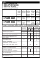
DATI TECNICI - TECHNICAL DATA - DONNEES TECHNIQUES TECHNISCHE DATEN - DATOS TÉCNICOS
Unità di misura
Unit of measure
Unité de mesure
Maßeinheit
Unidad de medida
Alimentazione - Power supply
Alimentation - Speisung - Alimentación
Corrente - Current - Courant - Strom - Intensidad
Potenza assorbita - Absorbed power
Puissance absorbée - AufgenommeneLeistung
Potencia absorbida
Velocità - Speed - Vitesse
Geschwindigkeit - Velocidad
Spinta max. - Maximum thrust
Pousèe maximum - Max. Schub - Empuje max.
Trazione - Traction - Traction - Antrieb - Traccion
Temperatura di esecizio - Working temperature
Température de service - Betriebstemperatur
Temperatura de servicio
Ciclo di lavoro - Working cycle
Cycle de travail - Arbeitszyklus - Ciclo de trabajo
Peso motore - Motor weight
Poids moteur - Motorgewicht - Peso del motor
Vac 50 Hz
Vdc
A
VA
m/s
N
N
°C (Min. / Max.)
%
kg
IP
230
24
0.5 0.65
120 150
0.12 0.15
650
650
-20° ÷ +70°
50 30
13
SP 6065 SP 6100
Grado di protezione - Protection level
Indice de protection - Schutzgart
Grado de protección
230
24
1.3 1.5
300 360
0.11 0.135
1000
1000
-20° ÷ +70°
30 20
14
40

3
Spider
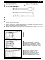
Porta sezionale (H max = 2400 mm)
Section door (H max. 2400 mm)
Porte à sections (H max. = 2400 mm)
Sektionstür (H max = 2400 mm)
Puerta seccional (H máx. = 2400 mm)
I
GB
F
D
E
I
GB
F
D
E
Lo SPIDER standard (corsa max 2500 mm.) può automatizzare porte a molle con altezza max fino a 2600 mm., porte
basculanti e porte sezionali a contrappesi con altezza max fino a 2400 mm..Per altezze differenti, vedere accessori opzionali.
The standard SPIDER (max. 2500 mm travel) model can automate spring overhead doors up to a height of 2600 mm.,
sectional and counterweight overhead doors up to 2400 mm. See the optional accessories for different heights.
Le SPIDER standard (course max. 2500 mm) peut automatiser des portes basculantes à ressorts d’une hauteur max. de
2600 mm., des portes à sections et portes basculantes à contrepoids d’une hauteur max. de 2400 mm.Pour des hauteurs
différentes, voir les accessoires en option.
Mit dem SPIDER in Standardausführung (max. Lauf 2500 mm) können Federschwingtüren mit einer Höhe bis maximal
2600 mm., Sektionstüren und Schwingtüren mit Gegengewichten mit einer Höhe bis maximal 2400 mm. automatisiert
werden. Für andere Höhen wird auf das Sonderzubehör verwiesen.
El modelo SPIDER estándar (carrera máx. 2500 mm) sirve para automatizar puertas basculantes de muelle de altura
máx. de hasta 2600 mm., puertas seccionales y basculantes con contrapesos de altura máx. de hasta 2400 mm. Para
alturas diferentes, véanse los accesorios opcionales.
Porta basculante a contrappesi (H max = 2400 mm)
Counterweight overhead door (H max. 2400 mm)
Porte basculante à contrepoids (H max. = 2400 mm)
Schwingtür mit Gegengewichten (H max = 2400 mm)
Puerta basculante con contrapeso (H máx. = 2400 mm)
Porta basculante a molle (H max = 2600 mm)
Spring overhead door (H max. 2600 mm)
Porte basculante à ressorts (H max. = 2600 mm)
Schwingtür mit Federn (H max = 2600 mm)
Puerta basculante de muelle (H máx. = 2600 mm)
I
GB
F
D
E
I
GB
F
D
E
APPLICAZIONI TIPICHE TYPICAL APPLICATIONS
APPLICATIONS TYPIQUES TYPISCHE ANWENDUNGEN
APLICACIONES HABITUALES
I
F
E
GB
D

4
Spider
GB
F
D
E
I
GB
F
D
E
I
VERIFICHE E
PRELIMINARI
1) Leggere attentamente le
istruzioni.
2) Accertarsi che la
struttura della porta sia
solida ed adatta ad
essere motorizzata.
3) Accertarsi che la porta
durante il suo
movimento non subisca
punti di attrito.
4) La porta dovrà essere
ben bilanciata.
Eventualmente, sarà
necessario intervenire
sui meccanismi di
bilanciamento.
5) Predisporre in
prossimità della
posizione prevista dello
SPIDER, una presa tipo
SCHUKO alimentata a
230V ed
adeguatamente protetta.
CHECKING AND
PRELIMINARY
PROCADURES
1) Read the instructions
carefully.
2) Make sure the door
structure is solid and
suitable to be motor
driven.
3) Make sure that when
the door is moving
there are no friction
points.
4) The door must be
properly balanced.To
the contrary the
balancing mechanisms
will have to be modified.
5) Install a 230 V,
adequately protected
SCHUKO socket near
where SPIDER is going
to be installed.
CONTROLES
PRELIMINAIRES
1) Lire attentivement les
instructions.
2) Contrôler que la
structure des portes est
solide et adaptée à être
équipée d’une
motorisation.
3) S’assurer que durant
son mouvement, la
porte ne subit pas de
points de frottement.
4) La porte doit être bien
équilibrée.
Eventuellement, il faudra
intervenir sur les
mécanismes
d’équilibrage.
5) Prévoir à proximité de la
position choisie pour le
montage du SPIDER
une prise type SCHUKO
alimentée à 230 V et
correctement protégée.
PRÜFUNGEN UND
VORBEREITEND
E ARBEITEN
1) Die Anleitungen genau
lesen.
2) Sicherstellen, dass die
Türstruktur solide und
für die Motorisierung
geeignet ist.
3) Sicherstellen, dass die
Tür während ihrer
Bewegung nicht reibt.
4) Die Tür muss richtig
ausgeglichen sein;
gegebenenfalls die
Ausgleichsvorrichtunge
n betätigen.
5) In der Nähe der für
SPIDER vorgesehenen
Position eine
SCHUKO
Steckdose mit 230V
Speisung und
passendem Schutz
vorsehen.
CONTROLES
PRELIMINARES
1) Lea atentamente las
instrucciones.
2) Cerciórese de que la
estructura de la puerta
sea sólida y apropiada
para ser motorizada.
3) Cerciórese de que
durante todo el
movimiento de la puerta
no se produzcan roces.
4) La puerta tiene que
estar perfectamente
equilibrada. Si fuera
necesario, actúe sobre
los mecanismos de
equilibrado.
5) Coloque en proximidad
de la posición prevista
para SPIDER un
tomacorriente tipo
SCHUKO, alimentado a
230V y protegido
adecuadamente.
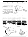
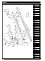
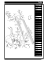
QUADRO D’INSIEME - OVERALL PICTURE - CADRE GENERAL
ÜBERSICHTZEICHNUNG - ESQUEMA DE CONJUNTO
1. SPIDER
2. Lampeggiante 24Vdc
3. Selettore o tastiera
digitale
4. Coppia di fotocellula
5. Pulsantiera interna
6. Presa Schuco
7. Lampadina 24V 15W
max
8. Pulsante passo-passo
1. SPIDER
2. 24Vdc flashing light
3. Key selector switch or
digital keypad
4. Pair of photocells
5.
Inside push-button panel
6. Schuko socket
7. 24V 15W max lamp
8.
Step-by-step push button
1. SPIDER
2. Clignotant 24Vdc
3. Sélecteur à clé avec
clavier numérique
4. Paire de photocellules
5. Clavier interne
6. Prise Schuko
7. Lampe 24V 15 W max
8. Bouton pas-à-pas
1. SPIDER
2. 24Vdc Blinklicht
3. Schlüsselwählschalter
oder Digitaltastatur
4. Photozellenpaar
5. Interne Druckknopftafel
6. Schüko-Steckdose
7. Lampe, 24V 15W max
8.Taste für Schrittzyklus
1. SPIDER
2. Luz intermitente de
24Vdc
3. Selector de llave, o
teclado digital
4. Par de fotocélulas
5.Teclado interior
6.Tomacorriente Shuko
7.
Bombilla de 24V 15W max
8. Botón paso a paso
2
2x1
+1xRG58
3
3x0,5
4x0,5
4
5
2x0,5
4x0,5
6
4
1
7
8

5
Spider
I
GB
F
D
E
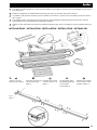
Lo SPIDER è stato progettato in modo da poterlo installare senza togliere il coperchio. Per l’assemblaggio seguire le pros-
sime descrizioni:
SPIDER is designed to be installed without removing the casing.To assemble it proceed as follows:
Le SPIDER a été projeté de manière à pouvoir l’installer sans retirer le couvercle. Pour l’assemblage, suivre les descrip-
tions ci-après:
Der SPIDER wurde so konstruiert, dass der Deckel bei seiner Installation nicht abgenommen werden muss. Für den
Zusammenbau nach den folgenden Beschreibungen vorgehen:
SPIDER ha sido proyectado para poder ser instalado sin quitar la tapa. Para el ensamblaje, siga las siguientes instruccio-
nes:
INSTALLAZIONE - INSTALLATION - INSTALLATION - INSTALLATION - INSTALACIÓN
GB
F
D
EI
Inserire le viti nella
feritoia come in figura 1.
Insert the screws in the
slot as shown in the
figure 1.
Introduire les vis dans
le fente comme sur la
figure 1.
Die Schrauben wie in
der Abbildung gezeigt
in den Schlitz
einschrauben 1.
Introduzca los tornillos
en las ranuras, como
muestra la figura 1.
1-
Fig. 1
Abb. 1

6
Spider
GB
F
D
EI
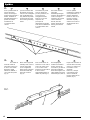
Unire i profili tramite le
aste di giunzione
forate; non stringere
troppo energicamente i
dadi A, altrimenti si
potrebbe deformare il
profilo ed indurire
inizialmente lo
scorrimento della
catena.
Join the sections with
the drilled connecting
rods; do not overtighten
nuts A otherwise they
may deform the profile
and prevent the chain
from running smoothly
at first.
Assembler les profils
avec les barres de
jonction perforées; ne
serrez pas trop
énergiquement les
boulons A car vous
risqueriez de
provoquer la
déformation du profilé
et de durcir initialement
le coulissement de la
chaîne .
Die Profile mit den
gelochten
Verbindungsstangen
vereinen; die Muttern A
nicht zu energisch
anziehen, da sich die
Leiste verformen
könnte, was das
Gleiten der Kette am
Anfang erschweren
würde.
Una los perfiles
mediante las verillas de
union perforadas; no
apriete demasiato
fuerte las tuercas A,
porque se podría
deformar el perfil y
endurecer al inicio el
deslizamiento de la
cadena.
GB
F
D
EI
Fare uscire la staffa di
traino B di lato ed
unirla alla catena con
la vite C ben stretta.
Riportare quindi
indietro la staffa B a
circa metà dei profili
(fig. 2).
Move chain support B
sideways and connect
it to the chain with
screw C tightened
firmly. Move support B
back about half way
along the sections
(Fig. 2).
Faire sortir l’étrier de
traction B sur le côté et
l’unir à la chaîne avec
le vis C bien serrée.
Reporter ensuite l’étrier
B vers l’arrière
approximativement au
milieu du profil (fig. 2)
Den Zugbügel B
seitlich heraustreten
lassen und mit der
schraube C gut fest an
der Kette verbinden.
Dann den Bügel B auf
etwa Hälfte Profil nach
hinten bringen (Abb. 2).
Haga salir el estribo de
arrastre B de costado y
ùnalo a la cadena con
la tornillos C bien
apretada.
Entonces, coloque
nuevamente hacia
atrás el estribo B,
hasta la mitad de los
perfiles (fig. 2).
2-
3-
Fig. 2
Abb. 2
B
A
C

7
Spider
GB
F
D
EI
Inserire il profilo
ottenuto nello Spider
facendo passare la
catena oltre il pignone
del motore e serrare le
viti D del collare E.
Mettere in leggera
tensione la catena
quindi serrare
definitivamente le viti
delle giunzioni.
Per un buon
funzionamento dello
Spider, lubrificare
bene la catena.
Insert the section
obtained in Spider,
passing the chain
beyond the motor’s
pinion and tighten the
collar E screws D.
Tighten the chain
slightly and then
tighten the connection
screws firmly.
Lubricate the chain
well to ensure that
Spider works well.
Introduire le profil
obtenu dans Spider en
faisant passer la
chaìne au-delà du
pignon du moteur et
serrer les vis D du
collier E.Tendre
légèrement la chaìne
puis serrer
definitivement les vis
des jonctions.
Pour un bon
foncionnement du
Spider, bien lubrifier
la chaìne.
Das so erhaltene Profil
in den Spider einfügen,
dabei die Kette über
das Motorritzel hinaus
führen und die
Schrauben D des
Bundringes E
anziehen. Die Kette
etwas spanned, dann
die Schrauben an den
Verbindungsstellen
endgültig anziehen.
Für einen korrekten
Betrieb des Spider die
Kette gut schmieren.
Introduzca el perfil
obtenido en el Spider,
vhaciendo pasar la
cadena más allá del
piñón del motor y
apriete los tornillos D
del collar E.Tense
ligeramente la cadena
y apriete
definitivamente los
tornillos de las
uniones. Para el
funcionamento correcto
de Spider, librique
bien lacadena.
GB
F
D
EI
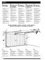
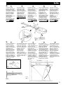
Fissare lo SPIDER al
telaio della porta
(scelta consigliata)
oppure al muro con
rivetti o tasselli (fig. 3)
rispettando una
distanza di 30 mm.
dalla corsa massima
della porta stessa
(fig. 4).Verificare le
misure per la foratura,
inserire e bloccare le
staffe di sostegno F e
fissare lo SPIDER al
soffitto (fig. 5).Tagliare
la parte eccedente
delle staffe.
Fix SPIDER to the door
frame (recommended
choice) or to the wall
with rivets and anchors
(Fig. 3), maintaining a
distance of 30 mm
from the door’s
maximum travel
(Fig. 4). Check
measurements for
drilling, insert and lock
the brackets F and fix
SPIDER to the ceiling
(Fig. 5). Cut off any
excess.
Fixer le SPIDER au
cadre de la porte
(choix conseillé) ou au
mur avec des vis
tamponnées (fig. 3) en
respectant une
distance de 30 mm par
rapport à la course
maximum de la porte
(fig. 4).Vérifier les
mesures pour le
perçage, introduire et
bloquer les étriers de
soutien F et fixer le
SPIDER au plafond
(fig. 5). Couper la partie
des étriers qui
dépasse.
Den SPIDER am
Türrahmen (empfohlen)
oder an der Wand mit
Nieten oder Dübeln
befestigen (Abb. 3),
dabei 30 mm Abstand
vom maximalen Lauf
der Tür halten (Abb. 4).
Nachdem die Maße für
die Lochung überprüft
worden sind, die
Tragbügel F einfügen
und blockieren den
SPIDER an der Deckel
befestigen (Abb. 5).
Den überschüssigen
Bügelteil abschneiden.
Fije SPIDER al marco
de la puerta (elección
aconsejada), o a la
pared, con remaches
(fig. 3), respetando una
distancia de 30 mm
desde la carrera
máxima de la puerta
(fig. 4). Controle las
medidas para la
perforación, introduzca
y bloquee los soportes
F y fije SPIDER al
techo (fig. 5). Corte la
parte excedente de los
soportes.
4-
5-
Fig. 4
Abb. 4
Fig. 3
Abb. 3
Fig. 5
Abb. 5

8
Spider
I
GB
F
D
E
INSERIMENTO SLITTE DI FINE CORSA
INSTALLATION OF THE ELEMENTS SLIDEING TO THE LIMIT SWITCH
MONTAGE DES ELEMENTS COULISSANTS POUR
MICROINTERRUPTEUR DE FIN DE COURSE
ANORDNUNG DER GLEITTEILE ZUM
ENDSCHALTER
INSTALACIÓN DE LAS PIEZAS DE
DESLIZAMIENTO A LOS
MICROINTERRUPTORES DE TOPE
GB
F
D
EI
POSIZIONAMENTO
DELLE SLITTE DI
FINE CORSA
Per il fissaggio delle
slitte di fine corsa
seguire quanto
descritto nelle istruzioni
allegate della “Centrale
Elettronica”.
POSITIONING THE
ELEMENTS LIMIT
SWITCH
To fix the sliding
elements follow the
instructions enclosed
with the “Electronic
Control Unit”.
POSITIONNEMENT
DES ELEMENTS
COULISSANTS POUR
MICROINTERRUPTEUR
DE FIN DE COURSE
Pour la fixation des
éléments coulissants
suivre les opérations
décrites dans les
instructions jointes se
référant à la “Centrale
Electronique”.
ANORDNUNG DER
GLEITTEILE ZUM
ENDSCHALTER
Für die Befestigung der
Gleitteile die
Anweisungen befolgen,
die der elektronischen
Steuerzentrale
beigefügt sind.
MONTAJE DE
LAS PIEZAS DE
DESLIZAMIENTO A
LOS MICROINTERRUPTOR
ES DE TOPE
Para la sujeción de las
piezas de
deslizamiento, siga las
instrucciones adjuntas
a la “Central
electrónica”.
I
GB
F
D
E
IMPORTANTE
Per avere una regolazione millimetrica nella manovra di chiusura, dopo aver posizionato le slitte
di fine corsa agire sull’asta di trasmissione (fig. 6) con chiave da 10 mm., allentando i bulloni e
regolando la corsa tramite le 2 asole; quindi richiudere energicamente i bulloni.
IMPORTANT
After the sliding elements have been positioned the closing manoeuvre has to be adjusted. To
obtain a millimetric adjustment, adjust the driving rod (Fig. 6) with a 10 mm spanner, loosening
the bolts and adjusting travel by means of the 2 slots, after which firmly tighten the bolts.
IMPORTANT
Pour obtenir un réglage millimétrique dans la manœuvre de fermeture, après avoir positionné les
éléments coulissants, agir sur la tige de transmission (fig.6) avec une clé de 10 mm en desserrant
les boulons ou en réglant la course avec les deux 2 fentes; puis resserrer énergiquement les
boulons.
WICHTIG
Damit die Bewegung in Schließung auf den Millimeter genau eingestellt wird, nach der Anordnung
der Gleitteile, die Mutterschrauben an der Antriebsstange (Abb. 6) lockern und den Lauf mit den
zwei Schlitzen einstellen; danach die Mutterschrauben wieder energisch anziehen.
IMPORTANTE
Para obtener una regulación micrométrica en la maniobra de cierre, tras haber instalado las
piezas de deslizamiento, actúe sobre la varilla de transmisión (fig. 6) con la llave de 10 mm,
aflojando los pernos y regulando la carrera mediante las 2 ranuras; luego, apriete los pernos.
FINE CORSA IN
APERTURA
STOP IN OPENING
MICROINTERRUPTEUR
DE FIN DE COURSE
EN OUVERTURE
ENDSCHALTER IN
ÖFFNUNG
MICROINTERRUPTOR
DE TOPE EN
APERTURA
FINE CORSA IN
CHIUSURA
LIMIT SWITCH IN
CLOSING
MICROINTERRUPTEUR
DE FIN DE COURSE EN
FERMETURE
ENDSCHALTER IN
SCHLIEßUNG
MICROINTERRUPTOR
DE TOPE EN CIERRA
Fig. 6
Abb. 6

Aprire lo sportello ed agire con cacciavite a taglio
sugli appositi trimmer, vedi le istruzioni allegate della
“Centrale Elettronica”.
Open the door and with an ordinary screwdriver
turn the trimmers; see the instructions attached to
the “Electronic Control Unit”.
Ouvrir la porte et agir avec un tournevis à fente
sur les trimmers de réglage, voir les instructions
jointes à la “Centrale Electronique”.
Den Deckel öffnen und mit einem
Schraubenziehen die entsprechenden Trimmer
betätigen, siehe auch Anleitungen, die der
“Elektronischen Steuerzentrale” beiliegen.
Abra la portezuela y actúe con un destornillador
sobre los trimmers; véanse las instrucciones
adjuntas de la “Central Electrónica”.
9
Spider
GB
F
D
EI
REGOLAZIONE
DELLA FORZA
MASSIMA
ADJUSTING
MAXIMUM FORCE
REGLAGE DE LA
FORCE MAXIMUM
EINSTELLUNG DER
HÖCHSTKRAFT
REGULACIÓN DE LA
FUERZA MÁXIMA
I
GB
F
D
E
GB
F
D
EI
REGOLAZIONE
DELLA VELOCITÀ
Per la regolazione della
velocità accedere alle
parti interne: aprire lo
sportello, svitare la vite
(G) e togliere il coperchio.
ATTENZIONE: il
coperchio funge da
protezione contro i contatti
diretti delle parti elettriche.
Prima di togliere il
coperchio, disinserire la
spina della presa di
corrente e mantenerla
scollegata fino al termine
delle operazioni.
Spostando il morsetto
da ( ) a ( ) si
diminuisce la velocità.
SPEED
ADJUSTMENT
For the speed adjustment
access the inside parts:
open the door and
unscrew screw (G) and
remove the casing.
ATTENTION: the casing
safeguards against direct
contact with the electrical
parts inside. Pull the plug
out of the socket before
removing the casing and
leave in out untill all work
has been done.
By moving the terminal
from ( ) to ( )
speed is reduced.
REGLAGE DE LA
VITESSE
Pour la réglage de la
vitesse accéder aux
parties internes: ouvrir la
porte et dévisser la vis (G)
puis enlever le couvercle.
ATTENTION: le couvercle
sert de protection contre
les contacts directs avec
les parties électriques
internes. Avant d’enlever le
couvercle, débrancher la
fiche de la prise de
courant et la laisser
débranchée jusqu’a la fin
des operations.
En déplaçant la borne
de ( ) à ( ) on
diminue la vitesse.
EINSTELLUNG DER
GESCHWINDIGKEIT
Für Einstellung der
Geschwindigkeit Zutritt zi
den Innentelen: den Deckel
öffnen und die Schraube.
Iosschrauben (G) dann den
Deckel abnehmen.
ACHTUNG: der Deckel
dient als Schutz gegen
direkte Kontakte mit den
elektrischen Innenteilen.
Bevor der Deckel
abgenommen der Deckel
abgenommen wird, den
Stecker aus der Steckdose
ziehen und bis zum Ende
der Arbeiten
herausgezogen lassen.
Die Geschwindigkeit wird
herabgesetzt, indem die
Klemme von
( ) auf ( )
verschoben wird.
REGULACION DE LA
VELOCIDAD
Para la regulacion de la
velocidad accerder a las
piezas interiores: abra la
portezuela y desenrosque
el tornillo (G) y luego quite
la tapa.
ATENCION: la tapa
cumpe la funciòn de
protecciòn contra los
contactos directos con las
piezas eléctricas
interiores. Antes de quitar
la tapa, desconecte el
enchufe del tomacorriente
y mantegalo
desconectando hasta
terminar las operaciopnes.
Desplazando el borne
desde ( ) a ( )
se disminuye la
velocidad.
G

10
Spider
ACCESSORI OPZIONALI
OPTIONAL ACCESSORIES
ACCESSOIRES EN OPTION
SONDERZUBEHÖR
ACCESORIOS OPCIONALES
GB
F
D
E
I
I
GB
F
D
E
I
GB
F
D
E
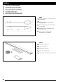
Prolunga da 1000 mm.
1000 mm extension.
Rallonge de 1000 mm.
1000 mm Verlängerung.
Elemento de prolongación de 1000 mm.
Braccio oscillante, per porte basculanti
a contrappesi.
Oscillating arm for counterweight
overhead doors.
Bras oscillant pour portes basculantes
à contrepoids.
Schwing arm, für schwingtüren mit
gegengewichten.
Brazo oscilante, para puertas
basculantes con contrapeso.
SPA 21
SPA 5

11
Spider
#
INFORMAZIONI PER L’UTENTE
Ad installazione avvenuta, l’utente deve essere informato sulle prestazioni dello SPIDER, e di tutti i rischi che possono derivare
da un uso improprio o scorretto. L’utente deve evitare di porsi in situazioni di pericolo, cioè stazionare nel raggio d’azione della
porta quando essa è in movimento, non opporsi al movimento della porta stessa, vietare ai bambini di giocare in prossimità della
porta e tenere fuori dalla loro portata i telecomandi.
Tutti gli interventi di manutenzione, riparazione o verifiche periodiche devono essere eseguiti da personale professionalmente
qualificato, documentati su apposito registro manutenzione custodito dall’utilizzatore.
- In caso di anomalia, l’utente deve astenersi da qualsiasi tentativo di intervento e chiamare l’installatore per la riparazione.
- L’utente può solo eseguire la mano
vra manuale e di passo-passo.
INFORMATION FOR THE USER
Once SPIDER has been installed, the user must be informed about how it works and all the risks that can arise if it is used
improperly.The user must avoid placing himself in dangerous situations such as standing within the door’s range of action when
it is moving, opposing its movement. Do not let children play near the door and keep the remote control out of their reach.
All servicing, repairs or checks must be carried out by professionally qualified personnel and noted on a maintenance register
kept by the user.
- in the case of malfunctioning the user must call the installer and not attempt to repair it himself.
- the user can only carry out the man
ual and step-by-step manoeuvres.
INFORMATIONS POUR L’USAGER
Une fois l’installation terminée, l’usager doit être informé sur les performances du SPIDER et sur tous les risques qui peuvent
dériver d’une utilisation impropre ou incorrecte. L’usager doit éviter de se mettre en situation de danger, c’est-à-dire de station-
ner dans le rayon d’action de la porte quand celle-ci est en mouvement; il ne doit pas non plus s’opposer au mouvement de la
porte. Il faut interdire aux enfants de jouer à proximité de la porte et il faut faire en sorte qu’ils ne puissent pas accéder aux
télécommandes.
Toutes les interventions d’entretien, réparation ou de contrôle périodique doivent être effectuées par du personnel profession-
nellement qualifié et elles doivent être documentées dans un registre d’entretien conservé par l’usager.
- En cas d’anomalie, l’usager doit s’abstenir de toute tentative d’intervention et faire appel à l’installateur pour la réparation.
- L’usager peut seulement effectuer la manúuvre man
uelle et de pas-à-pas.
INFORMATIONEN FÜR DEN BENUTZER
Nach erfolgter Installation muss der Benutzer über die Leistungen des SPIDER und über alle Risikos informiert werden, die
durch einen unsachgemäßen oder unkorrekten Gebrauch verursacht werden können. Der Benutzer muss vermeiden, sich in
Gefahrensituationen zu begeben, d.h. er darf nicht im Aktionskreis der sich bewegenden Tür verweilen, sich nicht der
Bewegung der Tür widersetzen, die Fernsteuerungen außer der Reichweite von Kindern halten und er muss diesen verbieten,
in der Nähe der Tür zu spielen.
Alle Wartungsarbeiten, Reparaturen oder regelmäßigen Überprüfungen dürfen nur von qualifiziertem Fachpersonal ausgeführt
werden und müssen im Wartungsbuch, das vom Benutzer aufbewahrt wird, eingetragen sein.
- Im Fall von Störungen muss sich der Benutzer Eingriffen enthalten und den Installateur mit der Reparatur beauftragen.
- Der Benutzer darf nur die man
uelle Betätigung und den Schrittzyklus ausführen.
INFORMACIONES PARA EL USUARIO
Cuando haya finalizado la instalación, informe al usuario sobre los rendimientos de SPIDER y sobre todos los riesgos que
puede correr a causa de un uso impropio o incorrecto del mismo. El usuario tiene que evitar situaciones de peligro, es decir
pararse en el radio de acción de la puerta cuando la misma está en movimiento, oponerse al movimiento de la misma, tam-
bién tiene que prohibir a los niños jugar en proximidad de la puerta y mantener fuera del alcance de los mismos los controles
remotos.
Todas las operaciones de mantenimiento, reparación, o controles periódicos tienen que ser efectuados por personal cualifica-
do, registradas y conservadas por el usuario.
– En caso de anomalía, el usuario tiene que abstenerse de efectuar cualquier reparación y llamar al instalador.
– El usuario puede efectuar sólo la maniobr
a manual y de paso a paso.
I
GB
F
D
E

12
Spider
#
GB
F
D
EI
MANOVRA
MANUALE
MANUAL
MANOEUVRE
MANŒUVRE
MANUELLE
MANUELLE
BETÄTIGUNG
MANIOBRA
MANUAL
I
GB
F
D
E
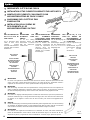
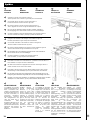
Collegare il carrello come indicato in figura 7.
Tirare il pomello verso il basso e agire sulla porta manualmente.
Connect the wire to the gear as shown in the figure 7.
Pull the knob down and move the door by hand.
Raccorder le câble au chariot comme l’indique la figure 7.
Tirer la poignée vers le bas et agir manuellement sur la porte.
Das Seil wie der Abbildung gezeigt mit dem Schlitten verbinden 7.
Den Kugelgrigg nach unten ziehen und die Tür von Hand betätigen.
Conecte el alambre al grupo de deslizamiento, como muestra la figura 7.
Accione el tirador hacia abajo y maneje la puerta manualmente.
I
GB
F
D
E
Collegare il filo metallico alla maniglia come indicato in figura 8.
Ruotare quest’ultima e agire sulla porta manualmente.
Connect the metal wire to the handle as shown in the figure 8.
Turn the handle and move the door by hand.
Raccorder le câble métallique à la poignée comme l’indique la figure 8.
Tourner cette dernière et agir manuellement sur la porte.
Das Metallseil wie in der Abbildung gezeigt mit dem Griff verbinden 8.
Den Griff und die Tür von Hand betätigen.
Conecte el alambre a la manija como muestra la figura 8.
Gire esta última y maneje la puerta manualmente.
I
GB
F
D
E
L’SP 6065 e SP 6100 sono dotati di sblocco a pomello e anche di sblocco a
fune metallica che si può manovrare dall’esterno.
SP 6065 and SP 6100 are equipped whit a knob for unlockingas well as a
metall cord that can be used on the outside.
L’SP 6065 et SP 6100 sont munis de déverrouillage à bouton ainsi que de
déverrouillage a câble métallique que l’on peut manoeuvrer de l’exterieur.
Der SP 6065 und SP 6100 sind mit Entriegelung durch Kugelgriff und auch mit
Entrigelung durch Metallseil ausgestattet, die von aussen her betätigt wrden kann.
Sp 6065 y SP 6100 estàn equipados con desbloqueo mediante manija y también
desbloqueo con cable metàlico, que se puede maniobrar desde afuera.
MANUTENZIONE
Lo SPIDER non richiede
particolari manutenzioni; è
bene, nonostante tutto,
verificare periodicamente
la tensione della catena e il
suo buon scorrimento; se
necessario lubrificarla
leggermente; verificare
che i collegamenti a vite
siano ben stretti. Per la
sostituzione della
lampadina utilizzare una di
similare (24V o 15W max).
Per altre manutenzioni fare
riferimento alle istruzioni
allegate alla”Centrale
Elettronica”.
MAINTENANCE
SPIDER requires no
specific maintenance.
However, it is good
practice to check chain
tension regularly and to
see that it slides properly;
lubricate if necessary.
Check that all screws are
tight. If the lamp needs
changing use one that is
similar (24V or 15W max.).
See the instructions
enclosed with the
“Electronic Control Unit”
for other maintenance
jobs.
ENTRETIEN
Le SPIDER ne demande
pas d’entretien particulier;
malgré tout, il est bon de
contrôler périodiquement
la tension de la chaîne et
son bon coulissement. Si
besoin est, la graisser
légèrement. Vérifier que
les vis assurant les
fixations sont bien serrées.
Si l’ampoule de l’éclairage
est grillée, la remplacer
par une de même type
(24V - 15 W max.). Pour
toutes les autres
opérations d’entretien,
suivre les instructions
jointes à la “Centrale
Electronique”.
WARTUNG
Für den SPIDER sind
keine besonderen
Wartungsarbeiten
erforderlich; trotzdem
sollten die
Kettenspannung und das
gute Gleiten der Kette
regelmäßg geprüft
werden: falls nötig, die
Kette leicht schmieren;
prüfen, ob die
Schraubverbindungen fest
angezogen sind. Die
Lampe mit einer ähnlichen
ersetzen (max. 24V oder
15W). Für andere
Wartungsarbeiten wird auf
die der “Elektronischen
Steuerzentrale”
beigelegten Anleitungen
verwiesen.
MANTENIMIENTO
SPIDER no requiere
mantenimiento particular.
Sin embargo, se aconseja
controlar periódicamente
la tensión de la cadena y
que la misma se deslice de
manera correcta; si fuera
necesario, lubríquela
ligeramente. Controle que
las conexiones con
tornillos estén bien
apretadas. Para sustituir la
bombilla, use una con las
mismas características
(24v o 15w máx.). Para las
demás operaciones de
mantenimiento, refiérase a
las instrucciones adjuntas
a la “Central Electrónica”.
I GB F D E
Fig. 7
Abb. 7
Fig. 8
Abb. 8
La pagina si sta caricando...
La pagina si sta caricando...
La pagina si sta caricando...

Apparecchiatura tipo ......................................................
Appliance type
Data di installazione .......................................................
Installation date
Installatore ......................................................................
Installer
Indirizzo .........................................................................
Address
Matricola .......................................................................
No. Code
Termine garanzia ............................................................
Warranty expiry date
Ditta ...............................................................................
Messrs
Telefono .........................................................................
Telephone
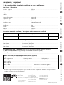
IMPORTANTE / IMPORTANT
Compilare ad installazione avvenuta e trattenere ad uso garanzia.
To be completed after installation and kept for use as a warranty
Dati cliente / Client data
Nome e cognome ........................................................ Telefono .....................................................................
Name and surname Telephone
Indirizzo ..................................................................................................................................................................
Address
Descrizione materiale installato / Description of the components installed
Centrale di comando Radio Dispositivi di sicurezza Note
Control box Radio Safety devices Notes
Controlli periodici / Periodical check-ups
Data / Date ................................... Descrizione / Description..............................................................................
Data / Date ................................... Descrizione / Description..............................................................................
Data / Date ................................... Descrizione / Description..............................................................................
Data / Date ................................... Descrizione / Description..............................................................................
Da compilare in caso di anomalia (inviare fotocopia della pagina allegandola all’attuatore in riparazione)
To fill in case of defect (send copy of the page enclosed with the actuator to be repaired)
Difetto segnalato / Defect ..........................................................................................................................................
.................................................................................................................................................................................
Parte riservata alla NICE SPA per comunicazioni al cliente
Space reserved for NICE SPA to communicate with the Clients
Data registrazione ..................................Data riparazione............................... N. Riparazione .............................
Date of registration Repair date Repair number
Parti sostituite .......................................................................................................................................................
Parts replaced
Note / Note....................................................................... Firma tecnico / Technician signature
.........................................................................................
......................................................................................... .................................................................
A termini di legge ci riserviamo la proprietà di questo manuale con divieto di riprodurlo o di renderlo comunque noto a terzi
o a ditte concorrenti senza nostra autorizzazione.
carta riciclata 100% recycled paper 100% papier recycle 100% 100% Altpapier 100% papel reciclado
IST SPI65 4865
CENTRO STAMPA S.r.l. - Oderzo (TV)
Nice SpA
Oderzo TV Italia
Via Pezza Alta, 13 Z.I. Rustignè
Tel. +39.0422.85.38.38
Fax +39.0422.85.35.85
Nice Belgium
Leuven (Heverlee) B
Tel. +32.(0)16.38.69.00
Fax +32.(0)16.38.69.01
Nice España Madrid E
Tel. +34.9.16.16.33.00
Fax +34.9.16.16.30.10
Nice France Buchelay F
Tel. +33.(0)1.30.33.95.95
Fax +33.(0)1.30.33.95.96
Nice Polska Pruszków PL
Tel. +48.22.728.33.22
Fax +48.22.728.25.10
www.niceforyou.com
-
 1
1
-
 2
2
-
 3
3
-
 4
4
-
 5
5
-
 6
6
-
 7
7
-
 8
8
-
 9
9
-
 10
10
-
 11
11
-
 12
12
-
 13
13
-
 14
14
-
 15
15
-
 16
16


Nice Automation Spider Manuale del proprietario
- Tipo
- Manuale del proprietario
- Questo manuale è adatto anche per
in altre lingue
Documenti correlati
Altri documenti
-
Nice Spider 6060 Manuale utente
-
Ferrari F355 Manuale del proprietario
-
Mutsy Spider Manuale utente
-
Lexibook JG6000SP Manuale utente
-
Primus Express Spider Manuale utente
-
IMG STAGELINE ECM-270 Manuale utente
-
Dirt Devil Robot M607 Manuale utente
-
-
Haba 302808 Manuale del proprietario
-