North Star NSR 17CS Istruzioni per l'uso
- Tipo
- Istruzioni per l'uso

Designed, Engineered &
Assembled in the U.S.A.
7351101 (Rev. D 6/12/17)
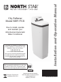
Installation and Operation Manual
How to install, operate
and maintain your
Ultra Demand Automatic
Water Conditioner
City Softener
Model NSR 17CS
Point-of-entry system tested and certified by
NSF International for NSF/ANSI 372, and is not
certified for material safety, contaminant reduc-
tions or structural integrity by NSF International.
Certified to
NSF/ANSI 372
If you have any questions or concerns when
installing, operating or maintaining your water
conditioner, call our toll free number:
1-800-972-0135
or visit www.northstarwater.com
When you call, please be prepared to provide
the model and serial number of your product,
found on the rating decal, located on the rim
below the salt lid hinges.
Manufactured and warranted by
North Star Water Treatment Systems
1890 Woodlane Drive
Woodbury, MN 55125

2
TABLE OF CONTENTS
Page
S
pecifications & Dimensions . . . . . . . . . . . . . . . . . . . . . . . . . . . . . . . . . . . . . . . . . . . . . . . . . . . . . . . . . . . . . . . . . . . 3
Before You Start . . . . . . . . . . . . . . . . . . . . . . . . . . . . . . . . . . . . . . . . . . . . . . . . . . . . . . . . . . . . . . . . . . . . . . . . . . . . 3
Installation Requirements . . . . . . . . . . . . . . . . . . . . . . . . . . . . . . . . . . . . . . . . . . . . . . . . . . . . . . . . . . . . . . . . . . . . 4-5
Installation Instructions . . . . . . . . . . . . . . . . . . . . . . . . . . . . . . . . . . . . . . . . . . . . . . . . . . . . . . . . . . . . . . . . . . . . . . 6-9
P
rogramming the Water Softener . . . . . . . . . . . . . . . . . . . . . . . . . . . . . . . . . . . . . . . . . . . . . . . . . . . . . . . . . . . . 10-11
Customizing Features / Options . . . . . . . . . . . . . . . . . . . . . . . . . . . . . . . . . . . . . . . . . . . . . . . . . . . . . . . . . . . . . 11-14
M
aintenance . . . . . . . . . . . . . . . . . . . . . . . . . . . . . . . . . . . . . . . . . . . . . . . . . . . . . . . . . . . . . . . . . . . . . . . . . . . . 15-16
Wiring Schematic . . . . . . . . . . . . . . . . . . . . . . . . . . . . . . . . . . . . . . . . . . . . . . . . . . . . . . . . . . . . . . . . . . . . . . . . . . 16
Troubleshooting . . . . . . . . . . . . . . . . . . . . . . . . . . . . . . . . . . . . . . . . . . . . . . . . . . . . . . . . . . . . . . . . . . . . . . . . . 17-19
Exploded View & Parts List . . . . . . . . . . . . . . . . . . . . . . . . . . . . . . . . . . . . . . . . . . . . . . . . . . . . . . . . . . . . . . . . 20-23
Bypass Blending Valve . . . . . . . . . . . . . . . . . . . . . . . . . . . . . . . . . . . . . . . . . . . . . . . . . . . . . . . . . . . . . . . . . . . . . . 24
WATER CONDITIONER WARRANTY
Warrantor: North Star Water Treatment Systems, 1890 Woodlane Drive, Woodbury, MN 55125
Warrantor guarantees, to the original owner, that:
One Year Full Warranty:
● For a period of one (1) year from the date of purchase, all parts will be free from defects in materials and workman-
ship and will perform their normal functions.
Limited Warranties:
● For a period of ten (10) years from the date of purchase, the salt storage tank and fiberglass mineral tank will not rust,
corrode, leak, burst, or in any other manner, fail to perform their proper functions.
● For a period of three (3) years from the date of purchase, the electronic control board and valve body will be free of
defects in materials and workmanship and will perform their normal functions.
If, during such respective period, a part proves to be defective, Warrantor will ship a replacement part directly to your
home, without charge.
General Provisions
Damage to any part of this water conditioner because of misuse, misapplication, neglect, alteration, accident, installation or
operation contrary to our printed instructions, or damage caused by any unusual force of nature such as, but not limited to,
freezing, flood, hurricane, tornado, or earthquake is not covered by this warranty. In all such cases, regular parts and serv-
ice charges will apply.
We assume no warranty liability in connection with this water conditioner other than specified herein. This warranty is in
lieu of all other warranties, expressed or implied, including warranties of fitness for a particular purpose. We do not author-
ize any person or representative to assume for us any other obligations on the sale of this water conditioner.
Should a defect or malfunction occur, contact your contractor. If you are unable to contact your contractor, return the part,
freight prepaid, directly to the factory at the address below. Enclose with the part a full description of the problem, with
your name, full address, date purchased, model and serial numbers, and selling contractor's name and address. We will
repair or replace the part and return it to you at no cost if our repair department determines it to be defective under the
terms of the warranty.
This warranty gives you specific legal rights and you may have other rights which vary from state to state.
This water conditioner is manufactured by
North Star Water Treatment Systems, 1890 Woodlane Drive, Woodbury, MN 55125
Customer Information Telephone No. 1-800-972-0135
Inspect Shipment
The parts required to assemble and install the water
softener are included with the unit. Thoroughly check
the water softener for possible shipping damage and
parts loss. Also inspect and note any damage to the
shipping carton.
Remove and discard (or recycle) all packing materials.
To avoid loss of small parts, we suggest you keep the
small parts in the parts bag until you are ready to use
them.

3
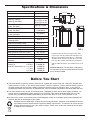
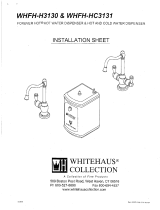
Specifications & Dimensions
Model NSR 17CS
M
odel Code CS17
Nominal Media Tank Size 9” dia. x 35”
Softening Capacity
(Grains @ Salt Dose)
9,388 @ 1.85 lbs.
1
4,175 @ 3.12 lbs.
18,951 @ 5.66 lbs.
Efficiency (Grains/Pound of Salt
@ Min. Salt Dose)
5,075 @ 1.85 lbs.
Water Used During Regeneration
@ Min. Salt Dose
4.8 gal. /
1,000 grains
Total Water Used Per Regeneration
@ Max. Salt Dose
46.2 gallons
Service Flow Rate 6.0 gpm
Amount of High Capacity Ion
Exchange Resin
0.62 cu. ft.
Amount of Activated Carbon 0.21 cu. ft.
Pressure Drop at Service Flow Rate 9.0 psig
Water Supply Max. Hardness 50 gpg
Intermittent Flow* @ 15 PSI 8.2 gpm
Water Pressure Limits (min. / max.) 20 - 125 psi
Water Temperature Limits (min. / max.) 40 - 120 °F
Minimum Water Supply Flow Rate 3 gpm
Maximum Flow Rate to Drain during
Recharge
2.0 gpm
0.50 ppm
Capacity at 0.75 ppm
Chlorine Concentration** of: 1.0 ppm
1.5 ppm
2.0 ppm
1,770,000 gal.
1,160,000 gal.
870,000 gal.
580,000 gal.
450,000 gal.
3-3/8”
18-7/8”
1
1-7/8”
OUT
IN
IN - OUT
FIG. 1
42”
37”
= The water softener requires a minimum water flow of 3 gallons per minute at the inlet. Maximum allowable inlet
water pressure is 125 psi. If your house water pressure is over the maximum, install a pressure reducing valve in
the water supply pipe to the system (Adding a pressure reducing valve may reduce the flow). If your home is
equipped with a back flow preventer, an expansion tank must be installed in accordance with local codes and laws.
= The water softener works on 24V DC electrical power, supplied by a direct plug-in power supply (included). Be
sure to use the included power supply and plug it into a nominal 120V, 60 Hz household outlet that is in a dry
location only, grounded and properly protected by an overcurrent device such as a circuit breaker or fuse.
= Do not use this system to treat water that is microbiologically unsafe or of unknown quality without adequate dis-
infection upstream or downstream of the system.
European Directive 2002/96/EC requires all electrical and electronic equipment to be disposed of accord-
ing to Waste Electrical and Electronic Equipment (WEEE) requirements. This directive or similar laws are
in place nationally and can vary from region to region. Please refer to your state and local laws for prop-
er disposal of this equipment.
Before You Start
*Intermittent flow rate does not represent the maxi-
mum service flow rate used for detemining the con-
ditioner’s rated capacity and efficiency. Continuous
operation at flow rates greater than the service flow
rate may affect capacity and efficiency performance.
**Typical residential chlorine concentration is 0.5 to 1.0
ppm.
Variable Salt Dose: The salt dose is selected by
the electronic controls at regeneration time based
on the amount needed.

4
LOCATION REQUIREMENTS
Consider all of the following when selecting an installa-
tion location for the water softener.
= Do not locate the water softener where freezing
temperatures occur. Do not attempt to treat water
over 120ºF. Freezing temperatures or hot water
damage voids the warranty.
= To condition all water in the home, install the water
softener close to the water supply inlet, and
upstream of all other plumbing connections, except
outside water pipes. Outside faucets should remain
on hard water to avoid wasting conditioned water
and salt.
= A nearby drain is needed to carry away regenera-
tion discharge (drain) water. Use a floor drain,
laundry tub, sump, standpipe, or other options
(check your local codes). See "Air Gap
Requirements" and "Valve Drain Requirements"
sections.
= The water softener works on 24V DC electrical
power, supplied by a direct plug-in power supply
(included). Provide nearby a 120V, 60 Hz electrical
outlet, in accordance with national and local codes.
= Always install the water softener between the water
inlet and water heater. Any other installed water
conditioning equipment should be installed between
the water inlet and water softener (See Figure 3
below).
= Avoid installing in direct sunlight. Excessive sun
heat may cause distortion or other damage to non-
metallic parts.
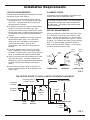
Installation Requirements
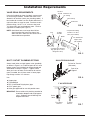
THE PROPER ORDER TO INSTALL WATER TREATMENT EQUIPMENT
FIG. 3
Pressure
Tank
City Water Supply
Well Water Supply
Well
Pump
OR
Optional
Sediment
Filter
Water
Heater
Water
Softener
Untreated Water to
Outside Faucets
Hot Water
to House
Cold Water
to House
PLUMBING CODES
All plumbing must be completed in accordance with
national, state and local plumbing codes.
LAUNDRY TUBSTANDPIPE
1-1/2”
air gap
FLOOR DRAIN
In the state of Massachusetts: The Commonwealth
of Massachusetts plumbing code 248-CMR shall
be adhered to. A licensed plumber shall be used
for this installation.
AIR GAP REQUIREMENTS
A drain is needed for regeneration water (See Figure
2). A floor drain, close to the water softener, is pre-
ferred. A laundry tub, standpipe, etc. are other drain
options. Secure valve drain hose in place. Leave an
air gap of 1-1/2” between the end of the hose and the
drain. This gap is needed to prevent backflow of
sewer water into the water softener. Do not put the
end of the drain hose into the drain.
FIG. 2
1-1/2”
air gap
Drain
Hose
Drain
Hose
1-1/2”
air gap
Drain
Hose

5
Installation Requirements
VALVE DRAIN REQUIREMENTS
Using the flexible drain hose (included), measure and
cut to the length needed. Flexible drain hose is not
allowed in all localities (check your plumbing codes). If
local codes do not allow use of a flexible drain hose, a
rigid valve drain run must be used. Purchase a com-
pression fitting (1/4 NPT x 1/2” minimum tube) and
1/2” tubing from your local hardware store. Plumb a
rigid drain as needed (See Figure 5).
NOTE: Avoid drain hose runs longer than 30 feet.
Avoid elevating the hose more than 8 feet
above the floor. Make the valve drain line as
short and direct as possible.
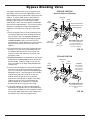
INLET / OUTLET PLUMBING OPTIONS
Always install either a single bypass valve (provided),
as shown in Figure 6, or, if desired, parts for a 3 valve
bypass system (not included) can be purchased and
assembled, as shown in Figure 7. Bypass valves
allow you to turn off water to the softener for mainte-
nance if needed, but still have water in house pipes.
Pipe fittings must be 3/4” minimum.
Use:
= Copper pipe
= Threaded pipe
= PEX (Crosslinked Polyethylene) pipe
= CPVC plastic pipe
= Other pipe approved for use with potable water
IMPORTANT: Do not solder with plumbing attached to
installation adaptors and single bypass
valve. Soldering heat will damage the
adaptors and valve.
FIG. 5
Clip
Barbs
1/4 NPT
Threads
1/2” Outside Dia.
Copper Tube
(not included)
Compression Fitting.
1/4 NPT x 1/2” O.D.
Tube (not included)
Cut barbs from drain fit-
ting (pull clip to remove
fitting from valve)
FIG. 7
3 VALVE BYPASS
From Water
Softener
To Water
Softener
Inlet
Valve
Outlet
Valve
Bypass
Valve
FIG. 4
1/4” NPT
Thread
Barbs for 3/8”
I.D. Tubing
Drain Hose
Hose Clamp
FIG. 6
SINGLE BYPASS VALVE
Pull out for “Service”
(Soft water)
Push in for
“Bypass”

6
Installation Instructions
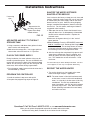
TURN OFF WATER SUPPLY
1. Close the main water supply valve, located near the
well pump or water meter.
2. Shut off the electric or fuel supply to the water
heater.
3. Open all faucets to drain all water from house pipes.
NOTE: Be sure not to drain water from the water
heater, as damage to the water heater ele-
ments could result.
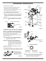
ASSEMBLY
1. North Star models are factory assembled. During
installation, remove the salt lid and set it aside to
prevent damage. Check the brinewell to be sure it
is secured and vertical (See Figure 11). Unsnap the
faceplate cover to expose the softener valve assem-
bly.
2. Lift the brine valve out of the brinewell. Make sure
the float stem is parallel to the stand tube so the
seals will seat properly during operation. Place the
brine valve back into the bottom of the brinewell and
reinstall the brinewell cover.
3. Install the brine tank overflow grommet and elbow
into the 13/16” diameter hole in the back of the salt
storage tank wall.
MOVE THE UNIT INTO PLACE
1. Move the water softener into the desired location.
Set it on a solid, level surface.
IMPORTANT: Do not place shims directly under the
salt storage tank to level the softener.
The weight of the tank, when full of
water and salt, may cause the tank to
fracture at the shim.
continued on next page
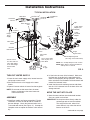
TYPICAL INSTALLATION
FIG. 8
Inlet
To Outside
Faucets
Conditioned
Water
Hard Water
M
a
i
n
W
a
ter
Pi
p
e
Plug-in
Power
Supply
Water Softener
V
alve
To
Controller
Valve Drain
Elbow
Valve Drain
Hose*
*Do not connect
the water softener
valve drain tubing
to the salt storage
tank overflow
hose.
Floor Drain
Overflow
Drain Elbow
Salt Storage
Tank Overflow
Hose*
Secure Valve Drain
Hose in place over
Floor Drain
NOTE: See “Air Gap Requirements” section.
NOTE: Water Softener shown with Salt Lid
and Top Cover removed
1-1/2”
air gap
Outlet
Clips
Pipe
1” NPT Sweat
Adaptor (not
included)
O-ring
Single
Bypass Valve
Lubricated
O-ring
1” NPT
Threaded
Adaptor
Blend Adjusting Knob
(See Page 24 for instructions)

7
Installation Instructions
FIG. 11
Top Cover
Brine Tank
O
verflow
Elbow
Brine Tank
Overflow
Grommet
13/16” Hole
Brinewell
Cover
Salt
Storage
Tank
Stand
Tube
Brine
Tubing
Salt
Lid
Float
Stem
Brine
Valve
Brinewell
Nozzle
Venturi
Assembly
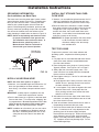
FIG. 9
Turbine
Turbine Support Assembly
Valve Outlet
FIG. 12
Clip
Channel
Single Bypass Valve
FIG. 13
Correct Assembly
Clip
Outside diameter
of clip channel on
single bypass valve
Outside diameter
of water softener
valve inlet & outlet
NOTE: Be sure all 3 tabs of the clip go through the matching
holes on the water softener valve inlet or outlet, and
fully into the channel on the single bypass valve.
Make sure that the tabs are fully seated.
c
ontinued from previous page
2. Visually check and remove any debris from the
w
ater softener valve inlet and outlet ports.
3
. Make sure the turbine assembly spins freely in the
"out" port of the valve (See Figure 9).
4. If not already done, put a light coating of silicone
grease on the single bypass valve o-rings.
5. Push the single bypass valve into the softener valve
as far as it will go. Snap the two large holding clips
into place, from the top down as shown in Figures
12 & 13.
IMPORTANT: Be sure the clips snap firmly into place
so the single bypass valve will not pull
out.
COMPLETE INLET AND OUTLET PLUMBING
Measure, cut, and loosely assemble pipe and fittings
from the main water pipe to the inlet and outlet ports of
the water softener valve. Be sure to keep fittings fully
together, and pipes squared and straight.
Be sure hard water supply pipe goes to the water sof-
tener valve inlet side.
NOTE: Inlet and outlet are marked on the water sof-
tener valve. Trace the water flow direction to
be sure hard water is to inlet.
IMPORTANT: Be sure to fit, align and support all
plumbing to prevent putting stress on
the water softener valve inlet and outlet.
Undue stress from misaligned or unsup-
ported plumbing may cause damage to
the valve.
Complete the inlet and outlet plumbing for the type of
pipes you will be using.
ALTERNATE BYPASS VALVE INSTALLATION
If connecting to floor
level plumbing, install
the bypass valve turned
downward, as shown.
IN
OUT
FIG. 10

8
Installation Instructions
INSTALL SALT STORAGE TANK OVER-
FLOW HOSE
1. Measure, cut to needed length and connect the 3/8”
drain line (provided) to the salt storage tank over-
flow elbow and secure in place with a hose clamp.
2 Route the hose to the floor drain, or other suitable
drain point no higher than the drain fitting on the salt
storage tank (This is a gravity drain). If the tank
overfills with water, the excess water flows to the
drain point. Cut the drain line to the desired length
and route it neatly out of the way.
IMPORTANT: For proper operation of the water soften-
er, do not connect the water softener
valve drain tubing to the salt storage
tank overflow hose.
TEST FOR LEAKS
To prevent air pressure in the water softener and
plumbing system, complete the following steps in
order:
1. Fully open two or more softened cold water faucets
close to the water softener, located downstream
from the water softener.
2. Place the bypass valve (single or 3 valve) into the
"bypass" position. See Figures 6 & 7 on Page 5.
3. Slowly open the main water supply valve. Run
water until there is a steady flow from the opened
faucets, with no air bubbles.
4. Place bypass valve(s) in "service" or soft water posi-
tion as follows:
= Single bypass valve: Slowly move the valve stem
toward "service," pausing several times to allow
the water softener to fill with water.
= 3 valve bypass: Fully close the bypass valve and
open the outlet valve. Slowly open the inlet
valve, pausing several times to allow the water
softener to fill with water.
5. After about three minutes, open a hot water faucet
until there is a steady flow and there are no air bub-
bles, then close this faucet.
6. Close all cold water faucets and check for leaks at
the plumbing connections that you made.
7. Check for leaks around clips at softener’s inlet and
outlet. If a leak occurs at a clip, depressurize the
plumbing (turn off the water supply and open
faucets) before removing clip. When removing clips
at the softener’s inlet or outlet, push the single
bypass valve body toward the softener (See Figure
15). Improper removal may damage clips. Do not
reinstall damaged clips.
INSTALL VALVE DRAIN HOSE
NOTE: See valve drain options on page 4.
1. Measure, cut to needed length and connect the 3/8”
drain line (provided) to the water softener valve
drain fitting. Use a hose clamp to hold the hose in
place.
IMPORTANT: If codes require a rigid drain line see
“Valve Drain requirements" section.
2. Run the drain hose (or a rigid line) to the floor drain.
Secure drain hose. This will prevent “whipping'' dur-
ing regenerations. Be sure to provide a 1-1/2” min -
imum air gap to prevent possible sewer water
backup. See “Air Gap Requirements" section.
NOTE: In addition to a floor drain, you can use a laun-
dry tub or standpipe as a good drain point for
this hose.. Avoid long drain hose runs, or ele-
vating the hose more than 8 feet above the
floor.
FIG. 14
Ground Wire
(not included)
Clamp
(2 - not included)
GROUNDING INFORMATION
(for Installations on Metal Pipe)
The house main incoming water pipe is often used to
ground electrical outlets in the home. Grounding pro-
tects you from electrical shock. Installing the water
softener with a plastic bypass valve will break this
ground. Before beginning installation, purchase and
securely install two grounding clamps and a #4 copper
wire across the location where the softener will be,
tightly clamping it at both ends, as shown in Figure 14.
NOTE: Check local plumbing and electrical codes
for proper installation of the ground wire.
The installation must conform to them. In
Massachusetts, plumbing codes of
Massachusetts shall be conformed to.
Consult with your licensed plumber.

9
Installation Instructions
ADD WATER AND SALT TO THE SALT
STOR AGE TANK
1. Using a container, add about three gallons of clean
water into the salt storage tank.
2. Add salt to the storage tank. Use nugget, pellet or
coarse solar salts with less than 1% impurities.
PLUG IN THE POWER SUPPLY
During installation, the water softener wiring may be
moved or jostled from place. Be sure all leadwire con-
nectors are secure on the back of the electronic board
and be sure all wiring is away from the valve gear and
motor area, which rotates during regenerations.
1. Plug the power supply into an electrical outlet that is
not controlled by a switch.
PROGRAM THE CONTROLLER
1. Install the softener’s top cover and salt lid.
2. Complete the programming steps on Page 10.
SANITIZE THE WATER SOFTENER /
SANITIZE AFTER SERVICE
Care is taken at the factory to keep your unit clean and
sanitary. Materials used to make the unit will not infect
or contaminate your water supply, and will not cause
bacteria to form or grow. However, during shipping,
storage, installation and operation, bacteria could get
into the unit. For this reason, sanitizing as follows is
suggested* when installing.
1. Slide open the salt lid, remove the brinewell cover
and pour about 3 oz. (6 tablespoons) of household
bleach into the softener brinewell. Replace the
brinewell cover.
2 Make sure the bypass valve(s) is in the “service”
(open) position.
3 Start a recharge: Press the RECHARGE button and
hold for 3 seconds, until “Recharge Now” begins to
flash in the display. This recharge draws the sanitiz-
ing bleach into and through the water softener. Any
air remaining in the unit is purged to the drain.
4. After the recharge has completed, fully open a cold
water faucet, downstream from the softener, and
allow 50 gallons of water to pass through the sys-
tem. This should take at least 20 minutes. Close
the faucet.
*Recommended by the Water Quality Association. On some
water supplies, the unit may need periodic disinfecting.
RESTART THE WATER HEATER
1. Turn on the electricity or fuel supply to the water
heater and relight the pilot, if applicable.
NOTE: The water heater is filled with hard water and,
as hot water is used, it refills with conditioned
water. In a few days, the hot water will be fully
conditioned. To have fully conditioned hot
water immediately, wait until the initial recharge
(previous step) is over. Then, drain the water
heater (following instructions for water heater)
until water runs cold.
FIG. 15
...depressurize the
plumbing, then push
Bypass Valve body
toward softener
I
f removing
clips...
Questions? Call Toll Free 1-800-972-0135 or visit www.northstarwater.com
When you call, please be prepared to provide the model and serial number,
found on the rating decal, located on the rim below the salt lid hinges.

10
Programming the Water Softener
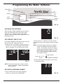
PROGRAM THE SOFTENER
When the power supply is plugged into the electrical
outlet, the model code (CS17) and a test number
(example: J3.8), are briefly shown in the display.
Then the words “PRESENT TIME” appear and 12:00
PM begins to flash.
SET PRESENT TIME OF DAY
If the words “PRESENT TIME" do not show in the dis-
play, press the SET button until they do.
1. Press the UP (È) or DOWN (–) buttons to set the
present time. Up moves the display ahead; down
sets the time back. Be sure AM or PM is correct.
NOTE: Press buttons and quickly release to slowly
advance the display. Hold the buttons down
for fast advance.
SET WATER HARDNESS NUMBER
1. Press the SET button once again to display a
flashing “25” and the word “HARDNESS”.
FIG. 16
Display
RECHARGE
button
FIG. 18
2. Press the UP (È) or DOWN (–) buttons to enter
the hardness of your water supply in grains per gallon
(gpg)
NOTE: If your water supply contains iron, compen-
sate for it by adding to the water hardness
number. For example, assume your water is
20 gpg hard and contains 2 ppm iron. Add 5
to the hardness number for each 1 ppm of
iron. In this example, you would use 30 for
your hardness number.
20 gpg hardness
2 ppm iron x 5 = 10 +10
(times) 30 HARDNESS NUMBER
3. Press the SET button once again to return to nor-
mal operating display.
FIG. 17
FIG. 19
DATA
button
DOWN
button
SET
button
U
P
button

11
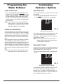
START A RECHARGE
1. Press the RECHARGE button and hold for three
seconds, until “RECHARGE” begins to flash in the
display, starting a recharge. This recharge draws
the sanitizing bleach into and through the water
softener. Any air remaining in the water softener is
purged to the drain. During this time, periodically
check for leaks.
NOTE: As with all other water system applications,
leaks may occur. Leaks may not be immedi-
ately apparent. Recheck for leaks 24 hours
after first recharge cycle is complete.
POWER OUTAGE MEMORY
If electrical power to the water softener is lost, “mem-
ory'' built into the timer circuitry will keep all settings
for several hours. While the power is out, the display
is blank and the water softener will not regenerate.
When electrical power is restored, the following will
occur:
Reset the present time only if the display is flashing.
The HARDNESS and RECHARGE TIME never
require resetting unless a change is desired. Even if
the clock is incorrect after a long power outage, the
softener operates as it should to keep your water soft.
However, regenerations may occur at the wrong time
of day until you reset the clock to the correct time of
day.
NOTE: If the water softener was regenerating when
power was lost, it will now finish the cycle.
RECHARGE NOW initiated
RECHARGE NOW
The RECHARGE button is used to initiate an immedi-
ate recharge.
1. Press and hold the RECHARGE button until the
words “RECHARGE NOW" flash in the display.
The softener enters the fill cycle of regeneration right
away. “RECHARGE NOW” will flash during the
regeneration. When completed, full water condition-
ing capacity is restored..
NOTE: Avoid using hot water while the softener is
regenerating, because the water heater will
refill with bypass hard water.
RECHARGE TONIGHT
If you do not want to start an immediate recharge, but
would like to schedule an extra recharge at the next
preset recharge time, do the following:
1. Press and release (do not hold) the RECHARGE
button.
The words “RECHARGE TONIGHT" flash in the dis-
play, and the softener will recharge at the next
recharge time. The words “RECHARGE NOW" will
flash during the regeneration. When completed, full
water conditioning capacity is restored.
RECHARGE TONIGHT initiated
Programming the
Water Softener
Customizing
Features / Options
FIG. 20
FIG. 21

12
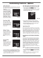
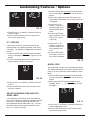
DATA DISPLAYS
With repeated presses of the DATA button, you can ob -
tain operational information about your water softener.
Capacity (remaining)
This is the percentage of
water softening capacity
remaining. Immediately
after a regeneration, 100%
shows. Then, as water is
used, the percentage
decreases until the next
regeneration. During
regenerations, the percen -
tage increments upward.
Customizing Features / Options
2. If you want to change the recharge start time,
press the UP (È) or DOWN (–) buttons until the
desired time shows. Be sure AM or PM is correct.
3. Press the SET button five times to return to the
normal run display (See Fig. 19).
VACATION NOTE
North Star demand water softeners, as set at the fac-
tory, recharge only while water is being used and soft-
ening capacity must be restored. For this reason, the
softener will not recharge when you are away from
home for extended periods. However, if you set the
“Maximum Days Between Recharges” feature, the
softener will regenerate even when no water is used.
MAXIMUM DAYS BETWEEN REGENERA-
TIONS
The water softener automatically controls regenera-
tion frequency. This provides the greatest operating
efficiency and, under most conditions, this feature
should be left in this automatic mode. However, you
may modify this feature if you want to force a regen-
eration every set number of days. For example, if
your water supply contains clear water iron, you may
want the softener to regenerate every few days to
keep the resin bed clean. The maximum days
between recharges may be set from 1 to 15 days, as
follows:
NOTE: The softener will recharge on its own if need-
ed, even if it is before the set number of days.
1. Press the SET button and hold for three seconds,
until the “Recharge Time” screen (Figure 26) is dis-
played.
2. Once in this display, press the SET button again
and the display in Figure 27 is shown.
SET RECHARGE (REGENERATION) TIME
1. Press the SET button and hold for three seconds,
until a flashing “2:00AM” and the words
“RECHARGE TIME” are displayed. This is a good
time for the recharge to start in most households,
b
ecause water is not in use.
FIG. 26
FIG. 22
FIG. 23
FIG. 24
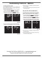
Flow Rate, GPM*
When using soft water,
this display shows the gal-
lons per minute flow rate
passing through the sof-
tener. Zero shows if water
is not in use.
Average Daily
Gallons*
The figure displayed is the
average gallons of water
used by the household
each day, over the past
seven day period.
Gallons* Today
Each day, beginning at
midnight, the timer keeps
a running count of the
total gallons of water
passing through the sof-
tener.
FIG. 25
*You can change the units displayed from gallons to
liters, or vice versa, as described on page 14. If gal-
lons today, or average daily gallons exceeds 1999, a
(x 10) indicator appears. This means you must mul-
tiply the number shown times 10.

13
MODEL CODE
The model code is factory set at assembly and testing.
The model code should never require resetting, but to
check, or to set if previously omitted, follow the steps
below.
1. Press the SET button and hold for three seconds,
until the “Recharge Time” screen (Figure 26) is dis-
played.
2. Again, press the SET button and hold for three
seconds. Either “- - - -” or the previously set code
will appear.
1. Press the SET button and hold
for three seconds,
until the “Recharge Time” screen (Figure 26) is dis-
p
layed.
2
. Once in this display, press the SET button three
times and the “Backwash Time” screen (Figure 29)
i
s displayed.
3. Press the UP (È) or DOWN (–) buttons to set ON
or OFF.
4. Press the SET button three times to return to the
normal run display.
ADJUST BACKWASH TIME AND FAST
RINSE TIMES
If you experience salty tasting water after regenera-
tion, you may need to increase the backwash and fast
rinse times. The default backwash and fast rinse
times depend on which model code is set. You may
increase or decrease the backwash and fast rinse
times, in 1 minute increments.
FIG. 27
Customizing Features / Options
3. Press the UP (È) or DOWN (–) buttons to set the
number of days.
4. Press the SET button four times to return to the
normal time of day screen.
97% FEATURE
If this feature is set ON, the unit will automatically
recharge when 97% capacity has been used, at any
time of day. The softener is shipped with this feature
set OFF.
1. Press the SET button and hold for three seconds,
until the “Recharge Time” screen (Figure 26) is dis-
played.
2. Once in this display, press the SET button twice
and the display in Figure 28 is shown.
FIG. 28
3. Use the UP (È) or
DOWN (–) buttons to
set the number of min-
utes desired for back-
wash.
4. Press the SET button
again to advance to the
“Rinse Time” screen
(Figure 30).
5. Use the UP (È) or
DOWN (–) buttons to
set the number of min-
utes desired for fast
rinse.
6. Press the SET button
once again to return to
the normal run display.
FIG. 29
FIG. 30
FIG. 31
3. Use the UP (È) or DOWN (–) buttons to select the
correct model code (CS17).
4. Press the SET button three times to return to the
normal time of day screen.

14
12 OR 24 HOUR CLOCK
All time displays are shown in 12 hour (AM/PM) clock
format at the default setting. If 24 hour clock format
is desired, follow steps below:
1. Press the SET button and hold for three seconds,
until the “Recharge Time” screen is displayed.
2. Again, press the SET button and hold for three
seconds, until the model code screen is displayed.
Customizing Features / Options
3. Once in this display, press the SET button again
and one of the two displays in Figure 33 is shown.
4. Press the UP (È) or DOWN (–) buttons to select
the time format.
5
. Press the SET button twice to return to the normal
time of day screen.
GALLON OR LITER VOLUME UNITS
At the default setting, all water flow rate and usage
displays are shown in gallons (GALS). Alternatively,
you may select liters for volume units to display.
1. Press the SET button and hold for three seconds,
until the “Recharge Time” screen is displayed.
2. Again, press the SET button and hold
for three
seconds, until the model code screen is displayed.
3. Once in this display, press the SET button twice
and one of the two displays in Figure 34 is shown.
FIG. 34
FIG. 32
FIG. 33
4. Press the UP (È) or DOWN (–) buttons to select
the volume units.
5. Press the SET button once again to return to the
normal time of day screen.
Questions? Call Toll Free 1-800-972-0135 or visit www.northstarwater.com
When you call, please be prepared to provide the model and serial number,
found on the rating decal, located on the rim below the salt lid hinges.

15
Water Softener Maintenance
REFILLING WITH SALT
Brine (salt dissolved in water) is needed for every
regeneration. The water for making brine is metered
into the salt storage area by the softener valve and
timer. If the water softener uses all the salt before
more is added, hard water will result. Lift the brine
tank lid and check the salt level every week. Be sure
that the brinewell cover is on when adding salt.
NOTE: In humid areas it is best to keep the salt level
less than half full and refill more often.
RECOMMENDED SALT: Cube, pellet, coarse solar,
etc., water softener salt is recommended. This type
of salt is high purity evaporated crystals, sometimes
formed and pressed into briquets. It has less than
1% insoluble (not dissolvable in water) impurities.
Clean, high grade rock salts are acceptable, but may
require frequent brine tank cleaning to remove the
“sludge” residue (insolubles) collecting at the bottom
of the tank.
SALT NOT RECOMMENDED: Rock salt high in
impurities, block, granulated, table, ice melting, or ice
cream making salts, etc., are not recommended.
SALT WITH IRON REMOVING ADDITIVE: Some
salts have an additive to help a water softener handle
iron in the water supply. Although this may help keep
the resin bed clean, it may also release corrosive
fumes that will weaken and shorten the life of some
water softener electronic parts.
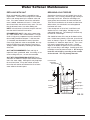
BREAKING A SALT BRIDGE
Sometimes a hard crust or salt “bridge” forms in the
brine tank. This is usually caused by high humidity or
the wrong kind of salt. When the salt bridges, an
empty space forms between the water and the salt.
Then salt will not dissolve in the water to make brine.
Without brine, the resin bed is not recharged and
hard water will result.
If the storage tank is full of salt, it is difficult to tell
whether there is a salt bridge. A bridge may be
underneath loose salt. The following is the best way
to check for a salt bridge:
Salt should be loose all the way to the bottom of the
tank. Hold a broom handle, or like tool, up to the sof-
tener, as shown in Figure 35. Make a pencil mark on
the handle 1-2” below the top of the rim. Then, care-
fully push it straight down into the salt. If a hard
object is felt before the pencil mark is even with the
top, it is most likely a salt bridge. Carefully push into
the bridge in several places to break it. Do not try to
break the salt bridge by pounding on the outside
of the salt tank. You may damage the tank.
FIG. 35
Push tool into
salt bridge
to break
1-2”
Pencil Mark
Broom
Handle
Water Level
Empty Space
Salt Bridge
Salt

16
Cap
O
-Ring Seal
Screen
S
upport
Screen
Nozzle & Venturi
Gasket
*Flow Plug
(HVDC)
Nozzle & Venturi
Housing
*Flow Plug
Screen
IMPORTANT: Be sure small holes in
the gasket are centered directly
over the small holes in the nozzle &
venturi housing.
*Install with numbered side up concave
side down. Be sure the largest flow plug
is located in the nozzle & venturi housing.
Water Softener Maintenance
CLEANING THE NOZZLE & VENTURI
A
clean nozzle & venturi (See Figure 36) is necessary
f
or the water softener to work properly. This small
u
nit creates the suction to move brine from the brine
t
ank into the resin tank. If it should become plugged
w
ith dirt, silt, sand, etc., the water softener will not
work and hard water will result.
To get access to the nozzle & venturi, remove the
softener’s top cover. Put the bypass valve(s) into the
bypass position. Be sure the softener is in the serv-
ice cycle (no water pressure at the nozzle & venturi).
Then, holding the nozzle & venturi housing with one
hand, turn the cap to remove it. Do not lose the o-
ring seal. Lift out the screen support and screen.
Then, remove the nozzle & venturi. Wash the parts in
warm, soapy water and rinse in fresh water. If need-
ed, use a small brush to remove iron or dirt. Be care-
ful not to scratch, misshape, etc., surfaces of the noz-
zle & venturi. Also, check and clean the gasket and
flow plug(s) if dirty.
Carefully replace all parts in the correct order.
Lubricate the o-ring seal with silicone grease and put
in place. Install and tighten the cap, by hand only.
Do not overtighten, which could break the cap or
housing. Put the bypass valve(s) into service (soft
water) position.
RESIN BED CLEANING
If the water supply contains clear water iron, regular
resin bed cleaning is needed to keep the bed from
coating with iron. Use resin bed cleaner, following
directions on the container. Clean the resin every six
months, or more often if iron appears in the condi-
tioned water supply.
FIG. 36
FIG. 37
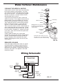
Wiring Schematic
Back of Electronic
Controller (PWA)
Pwr.
In
Pos./Turbine
Motor
OUT
+5
GND
Turbine
Sensor
Valve
Motor
NO
Position
Switch
NC
24V DC
120V AC
60Hz
Power
Supply
C

17
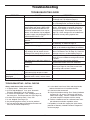
Troubleshooting
PROBLEM CAUSE CORRECTION
N
o soft water
N
o salt in the storage tank.
A
dd salt (See Page 15) and then initiate a
“Recharge now,” as shown on Page 11.
Salt is “bridged.” Break salt bridge (See Page 15) and then initi-
ate a “Recharge now,” as shown on Page 11.
If display is blank, power supply may be
unplugged at wall outlet, power cable
leads may be disconnected from the
electronic control board, fuse may be
blown, circuit breaker may be popped,
or power supply may be plugged into a
switched outlet which is “off.”
Check for power loss due to any of these and
correct. When power is restored, if the time is
flashing in the display, it means time was lost
during the outage. Set the present time (See
Page 10). Other settings such as hardness are
retained in memory during a power loss.
Manual bypass valve(s) in bypass
position.
Place bypass valve(s) in service position.
Dirty, plugged or damaged nozzle &
venturi.
Take apart, clean and inspect the nozzle & ven-
turi assembly, as shown on Page 16.
Valve drain hose plugged or restricted. Drain hose must not have any kinks, sharp
bends, or be raised too high above the softener.
Water hard sometimes Bypassed hard water being used dur-
ing recharge, due to present time or
recharge time settings being incorrect.
Check the present time displayed. If not correct,
refer to “Set Present Time” on Page 10. Check the
recharge start time, as described on Page 12.
Hardness number setting is too low. Referring to “Setting Hardness” on Page 10,
check the current hardness setting and increase
if needed.
Hot water being used when softener is
recharging.
Avoid using hot water during recharges,
because water heater refills with hard water.
Increase in actual hardness of water
supply.
Have unsoftened water sample tested.
Referring to Page 10, check the current hard-
ness setting and increase if needed.
Motor stalled or clicking Motor malfunction or internal valve
fault causing high torque on motor.
Contact your dealer for service.
Error code E1, E3 or E4
displayed.
Fault in wiring harness, connections to
position switch, switch, valve or motor.
Contact your dealer for service.
Error code E5 displayed. Electronic control malfunction. Contact your dealer for service.
TROUBLESHOOTING GUIDE
TROUBLESHOOTING - INITIAL CHECKS
Always make these initial checks first:
1. Is display blank? Check power source.
2. Is Error code displayed? If so, go to “Automatic
Electronic Diagnostics” on the next page.
3. Is correct time displayed? If not, recharges occur at
the wrong time. Set the present time (See Page 10.)
4. Is there salt in the brine tank? If not, refill.
5. Is salt “bridged” (See Page 15)?
6. Are plumbing bypass valve(s) in service position?
7. Are inlet and outlet pipes connected to the water sof-
tener inlet and outlet respectively?
8. Is valve drain hose free of kinks and sharp bends,
and not elevated over 8 feet above the floor.
9. Is the brine tube connected?
10. Check the hardness setting (See “Setting Hardness
on Page 10). Be sure it is correct for the house-
hold's water supply. Perform a hardness test on a
raw water sample to compare with the setting.
11. Perform a hardness test on a softened water sam-
ple to determine whether a problem exists.
If no problem is found after making the initial checks,
proceed to “Manually Initiated Electronic Diagnostics”
on the next page.

18
Troubleshooting
While an error code appears in the display, all buttons
are inoperable except the SET button. SET remains
operational so the service person can perform the
Manually Initiated Electronic Diagnostics, see below,
to further isolate the problem.
Procedure for removing error code from dis-
play:
1. Unplug power supply from electrical outlet.
2. Correct problem.
3. Plug power supply back in.
4. Wait 8 minutes. The error code will return if
the problem was not corrected.
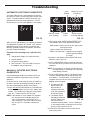
MANUALLY INITIATED ELECTRONIC
DIAGNOSTICS
Use the following procedures to advance the water
softener through the regeneration cycles to check
operation.
Lift off the salt lid, remove the top cover by unlocking
the tabs in the back and rocking forward, to observe
cam and switch operation during valve rotation.
1. Press and hold
the DATA button for 3 seconds until
one of the two displays in Figure 39 is shown, then
release. The number in the top part of the display,
after “dY”, is days since the last recharge.
NOTE: If the softener is in the middle of a regenera-
tion, the top part of the display shows the
cycle of regeneration, and minutes of the
cycle remaining. If two cycle names are flash-
ing, the valve is in transition between the
cycles.
2. The 3 digits under WATER MANAGEMENT SYS-
TEM indicate water meter operation as follows:
000 (steady) = Soft water not in use, and no flow
through the meter.
Open a nearby soft water faucet.
000 to 199 (continual) = Repeats for each gallon
of water passing through
the meter.
3. Symbols in the display indicate POSITION switch
operation (See Figure 39).
4. Use the RECHARGE button to manually advance
the valve into each cycle and check correct switch
operation.
NOTE: Be sure water is in contact with the salt, and
not separated by a salt bridge (See "Breaking
A Salt Bridge" section).
5. Press the DATA button again. The following infor-
mation is available and may be beneficial for vari-
ous reasons. This information is retained by the
computer from the first time electrical power is
applied to the face plate.
a. The top half of the
display shows the
total number of
recharges since the
timer was connected
to electrical power.
b. The bottom half of
the display shows the
number of days since
the timer was con-
Switch is open
(Cam not rotating)
Switch is closed
(Cam rotating)
AUTOMATIC ELECTRONIC DIAGNOSTICS
This water softener has a self-diagnostic function for
the electrical system (except input power and/or water
meter). The water softener monitors electronic com-
ponents and circuits for correct operation. If a mal-
function occurs, an error code appears in the display.
FIG. 38
FIG. 39
V
alve
Position
M
inutes of Cycle
Remaining
Turbine
Count
FIG. 40
nected to electrical power. If over 1999 days, a
(x 10) indicator shows, meaning you must multi-
ply the number shown times 10.
6. Press DATA once again to return to the normal
time of day screen.

19
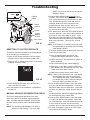
M
otor
Turbine
Support
& Shaft
Position
Switch
Sensor
Housing
Turbine
Valve Outlet
FIG. 41
Troubleshooting
This check verifies proper operation of the valve
motor, brine tank fill, brine draw, regeneration flow
rates, and other controller functions. Always make
the initial checks, and the manual initiated diagnos-
tics.
NOTE: The electronic control display must show a
steady time (not flashing). If an error code
MANUAL ADVANCE REGENERATION CHECK
s
hows, first press the SET button to enter the
diagnostic display.
1. Press the RECHARGE button and hold
in for 3
s
econds. RECHARGE begins to flash as the soft-
ener’s valve advances from the service to fill posi-
t
ion. Remove the brinewell cover and, using a
flashlight, observe fill water entering the tank.
If water does not enter the tank, look for an
obstructed nozzle, venturi, fill flow plug, brine tub-
ing, or brine valve riser pipe.
2. After observing fill, press the RECHARGE button to
move the softener’s valve into the brine position. A
slow flow of water to the drain will begin. Verify
brine draw from the brine tank by shining a flash-
light into the brinewell and observing a noticeable
drop in the liquid level. This may take 15 to 20
minutes.
NOTE: Be sure water is in contact with the salt, and
not separated by a salt bridge (See "Breaking
A Salt Bridge" section).
If the water softener does not draw brine, check for
(most likely to least likely):
= Dirty or plugged nozzle and venturi, see
"Cleaning the Nozzle and Venturi" section.
= Nozzle and venturi not seated on the gasket, or
gasket deformed.
= Valve seals leaking (See Troubleshooting).
= Restriction in valve drain, causing a back-pres-
sure (bends, kinks, elevated too high, etc.). See
"Install Valve Drain Hose" section.
= Obstruction in brine valve or brine tubing.
NOTE: If water system pressure is low, a too-long or
elevated drain hose may cause back pres-
sure, stopping brine draw. Avoid drain hose
runs longer than 30 feet. Avoid elevating the
hose more than 8 feet above the floor.
3. Press the RECHARGE button to move the soften-
er’s valve into the backwash position. Look for a
fast flow of water from the drain hose. Check that
the drain can adequately handle the flow and vol-
ume.
An obstructed flow indicates a plugged top distribu-
tor, backwash flow plug, or drain hose.
4. Press the RECHARGE button to move the soften-
er’s valve into the fast rinse position. Again look
for a fast drain flow. Allow the softener to rinse for
a few minutes to flush out any brine that may
remain in the resin tank from the brining cycle test.
5. To return the softener’s valve to the service posi-
tion, press the RECHARGE button.
RESETTING TO FACTORY DEFAULTS
To reset the electronic controller to its factory default
for all settings (time, hardness, etc.):
1. Press the SET button and hold it until the display
changes twice to show the flashing model code.
2. Press the UP (È) button (a few times, if necessary)
to display a flashing “SoS”.
3. Press the SET button three times, and the elec-
tronic controller will restart.
4. Set the present time and hardness, as described
on page 10.
FIG. 42

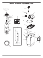
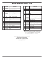
20
Water Softener Exploded View
1
4
2
3
5
6
7
10
8
9
15
16
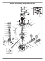
Valve Assembly
See Pages 22 & 23
for parts
13
14
12
17
18
20
19
23
25
24
11
26
22
21
La pagina si sta caricando...
La pagina si sta caricando...
La pagina si sta caricando...
La pagina si sta caricando...
-
 1
1
-
 2
2
-
 3
3
-
 4
4
-
 5
5
-
 6
6
-
 7
7
-
 8
8
-
 9
9
-
 10
10
-
 11
11
-
 12
12
-
 13
13
-
 14
14
-
 15
15
-
 16
16
-
 17
17
-
 18
18
-
 19
19
-
 20
20
-
 21
21
-
 22
22
-
 23
23
-
 24
24


North Star NSR 17CS Istruzioni per l'uso
- Tipo
- Istruzioni per l'uso
in altre lingue
Documenti correlati
Altri documenti
-
EcoWater eVOLUTION Power 600 Instructions Manual
-
Power Fist 8455099 Manuale del proprietario
-
Fleck 4600 Manuale del proprietario
-
Sammic DS-12 Manuale utente
-
Rancilio Epoca S1 Use And Maintenance
-
ELEKTRA Professional espresso coffee machines Manuale utente
-
Hendi 299265 Manuale utente
-
Culligan Mark 59 Guida utente
-
 Whitehaus Collection WHFH-HC3131-MABRZ Guida d'installazione
-
 RainSoft HDINSTIUDWS Manuale utente

