
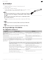
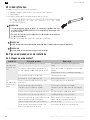
Sonesse 40 RS485
EN Instructions
DE Anleitung
FR Notice
IT Istruzioni
ES Manual de instrucciones
PT Instruções
DA Anvisninger
NO Veiledning
FI Käyttöohje
SV Bruksanvisning
NL Handleiding
RU Инструкции
ZH
AR

EN Sonesse 40 RS485
2Copyright© 2021 SOMFY ACTIVITES SA. All rights reserved.
ORIGINAL INSTRUCTIONS
These instructions apply to all Sonesse 40 RS485 drives, the different versions of which are available in the current
catalogue.
CONTENTS
1.
Prior information..........................................................................................................................................................
2
1.1.
Field of application..........................................................................................................................................
2
1.2.
Liability .............................................................................................................................................................
3
2.
Installation.....................................................................................................................................................................
3
2.1.
Assembly ..........................................................................................................................................................
3
2.2.
Wiring ...............................................................................................................................................................
5
2.3.
Commissioning ................................................................................................................................................
6
2.4.
Tips and advice on installation.......................................................................................................................
6
3.
Use and maintenance ...................................................................................................................................................
7
3.1.
Operation .........................................................................................................................................................
7
3.2.
PROG button...................................................................................................................................................
7
3.3.
LED feedback ...................................................................................................................................................
7
4.
Tips and advice on operation ......................................................................................................................................
8
4.1.
Questions about the drive?............................................................................................................................
8
5.
Technical data ...............................................................................................................................................................
8
GENERAL INFORMATION
Safety instructions
DANGER
Indicates a danger which may result in immediate death or serious injury.
WARNING
Indicates a danger which may result in death or serious injury.
PRECAUTION
Indicates a danger which may result in minor or moderate injury.
CAUTION
Indicates a danger which may result in damage to or destruction of the product.
1.PRIOR INFORMATION
1.1.Field of application
The Sonesse 40 drives are designed to drive all types of interior blinds except pantographs.

Sonesse 40 RS485 EN
Copyright© 2021 SOMFY ACTIVITES SA. All rights reserved. 3
The installer, who must be a motorisation and home automation professional, must ensure that the motorised product is
installed in accordance with the standards in force in the country in which it is installed such as EN13120 relating to interior
blinds.
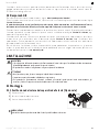
1.2.Liability
Before installing and using the drive, please read these instructions carefully.
In addition to the instructions provided in this guide, please also comply with the instructions provided in the attached Safety
instructions document.
The drive must be installed by a home motorisation and automation professional, in accordance with Somfy’s
instructions and the applicable regulations in the country of installation.
Any operation of the drive outside the field of application described above is prohibited. Such use, and any failure to comply
with the instructions given in this guide and in the attached Safety instructions document, absolves Somfy of any liability and
invalidates the warranty.
After installing the drive, the installer must inform his customers of the operating and maintenance conditions for the drive
and must provide them with the operating and maintenance instructions, and the attached Safety instructions document.
Any After-Sales Service operation on the drive must be performed by a home motorisation and automation professional.
Never begin installing without first checking the compatibility of this product with the associated equipment and
accessories. If in doubt when installing this product and/or to obtain additional information, contact a Somfy representative
or visit the website www.somfy.com.
2.INSTALLATION
WARNING
•
These instructions are mandatory for the home motorisation and automation professional installing the drive.
•
Comply with current standards and legislation in the country of installation.
CAUTION
•
Never drop, knock or puncture the drive or immerse it in liquid.
•
Install an individual control point for each drive.
•
To insure optimized silent operation, the gaps between the drive, the accessories, the tube and the tube end piece
must be minimized.
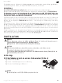
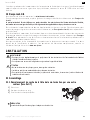
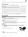
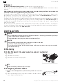
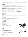
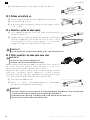
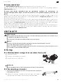
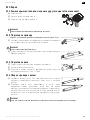
2.1.Assembly
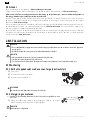
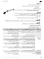
2.1.1.Replace the head cover with a different color (Optional)
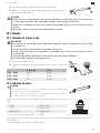
1] Remove the screw.
2] Replace the cover with a new cover.
3] Screw the cover at 0,4 N·m.
NOTICE
Head has interchangeable covers to fit with the fabric.
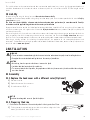
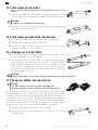
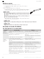
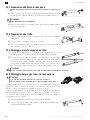
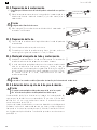
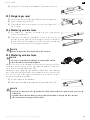
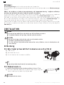
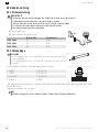
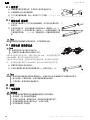
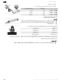
2.1.2.Preparing the drive
üCheck that the inner diameter of the motorised product’s tube is greater than 37mm.
1] Fit the accessories required to integrate the drive into the winding tube: fit the
crown (a) and the drive wheel (b) to the drive.
a
b

EN Sonesse 40 RS485
4Copyright© 2021 SOMFY ACTIVITES SA. All rights reserved.
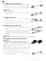
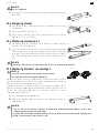
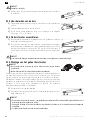
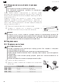
CAUTION
The crown is mandatory.
2] Measure the length (L) between the inner edge of the drive head and the rim
of the drive wheel.
L
L = …
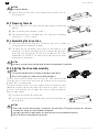
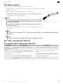
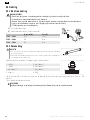
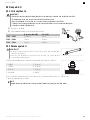
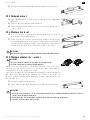
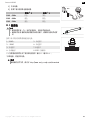
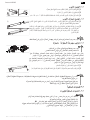
2.1.3.Preparing the tube
1] Cut the winding tube to the required length, depending on the motorised
product.
2] Deburr the winding tube and remove the swarf.
3] For winding tubes which are smooth inside, cut a notch with the following
measurements: l= 7mm, L= 10mm.
1] 2]
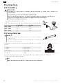
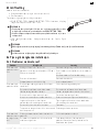
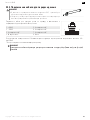
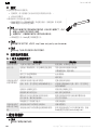
2.1.4.Assembling the drive-tube
1] Slide the drive into the winding tube. For winding tubes with a smooth
interior, position the cut notch on the crown.
2] The drive wheel must be locked in place to prevent any movement in the
winding tube: This can be achieved by fastening the winding tube to the drive
wheel using 4 self-tapping screws, Ø 5 mm, or 4 steel pop rivets, Ø 4.8 mm,
placed between 5 mm and 15 mm from the outer edge of the drive wheel,
regardless of the winding tube.
1]
2]
L
CAUTION
The screws or pop rivets must only be fastened onto the drive wheel and not on the drive.
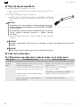
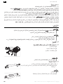
2.1.5.Installing the drive-tube assembly
CAUTION
•
The motorised product must not be compressed between the brackets.
•
Do not use the plastic cross without the metal bracket adapter.
The drive can be fixed directly onto the drive bracket (the screw holes are spaced
29mm apart). Use 2 screws 4x8mm delivered with the motor. A manual tightening
torque of 1.5N·m is recommended.
Drive plates are also available in the current catalogue (Select the correct drive plate
adapted to the bracket and check the torque requirements in the system). Use the 2
screws 3 x 6 mm delivered with the motor plate. A manual tightening torque of
0.6N·m is recommended.
1] Screw the bracket adapter to the drive head.
2] Install and fix the drive-tube assembly onto the end bracket (c) and onto the
drive bracket (d).
d
c
CAUTION
•
Ensure that the drive-tube assembly is secured onto the end bracket. This operation prevents the tube-drive
assembly from coming out of the end bracket attachment.
•
Light gap reduced: Do not pinch cables or be careful they are not in contact with moving parts.
•
Do not let the drive-tube hanged by only one side.

Sonesse 40 RS485 EN
Copyright© 2021 SOMFY ACTIVITES SA. All rights reserved. 5
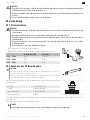
2.2.Wiring
2.2.1.Power wiring
PRECAUTION
•
Cables which pass through a metal wall must be protected and isolated using a sheath or sleeve.
•
Secure cables to prevent any contact with moving parts.
•
The drive cable cannot be removed. If it is damaged, return the drive to the After-Sales department.
•
Leave the drive power supply cable accessible: it must be easily replaceable.
•
Connection must be done in a junction box.
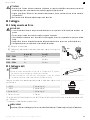
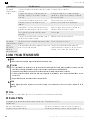
1] Switch off the power supply.
2] Connect the drive according to the information in the table below:
Neutral (N) Live (L)
120 V 50 Hz White Black
220 V 60 Hz Blue Brown
230 V 50 Hz Blue Brown
OFF
N
L
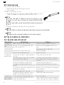
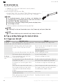
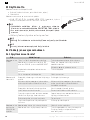
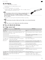
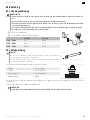
2.2.2.Data wiring
CAUTION
•
There is a RJ45 female to female coupler provided with the drive to add easily an
extension cable.
•
Make sure the data cable is not pinched or damaged during the installation of the
drive/tube onto the end bracket.
Connect the data cable to the drive according to the information in the tables below.
1: + RS485 5: Not connected**
2: - RS485 6: Not connected**
3: Not connected** 7: Not connected**
4: Power out * 8: GND
5
6
7
8
4
3
2
1
* The LSU Power Out characteristics comply with the following voltage and current characteristics: 8 V min – 50 mA max.
** If connected, the drive can be damaged.
NOTICE
The wiring guide is available for download at https://www.somfy.com/projects/downloads

EN Sonesse 40 RS485
6Copyright© 2021 SOMFY ACTIVITES SA. All rights reserved.
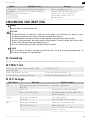
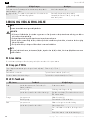
2.3.Commissioning
The drive has 2 blinds profile inside:
Roller mode (to control all blinds except Venetians).
Venetian mode.
Two tools are available to set the drive.
RS485 SETTING TOOL: Connect the RS485 SETTING TOOL to the drive
switch on and follow the instruction on the RS485 SETTING TOOL.
NOTICE
•
Venetian mode allows to manage the tilt and the lift position. It is not
possible to set the drive-in venetian mode through the RS485 SETTING
TOOL.
•
When setting end limits, take care that the load bar remains free at upper end
Limit.
SDN Config Tool: Somfy Digital Network Configuration Tool.
NOTICE
The SDN Config Tool is available for download at https://www.somfy.com/projects/downloads
NOTICE
The different versions of which are available in the current Somfy catalogue.
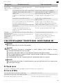
2.4.Tips and advice on installation
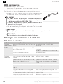
2.4.1.Questions about the drive?
Observations Possible causes Solutions
The motorised
product does not
work.
"Power" or "datas" wiring are incorrect. Check the wiring and modify it if necessary.
The drive is in thermal protection mode. LED
Red=ON then lightsOFF. Wait for the drive to cool down to restart the
drive.
Do not touch the drive: risk of burns.
An incorrect Data cable has been used Check the Data cable.
End-limits are not properly adjusted. Adjust the end-limits.
The motorised
product is noisy. The wheel and the crown are not adapted to the
used tube. Change the wheel and the crown.
The mechanical plays between drive, accessories,
tube and end of tube are too high. The mechanical plays between drive, accessories,
tube and end of tube must be decreased to the
minimum.
The wheel is not properly fixed to the tube. Fix the wheel properly to the tube.
The equipment is constrained between the
brackets. Decrease the constraint between the brackets.
The length of the notch is not adapted to the drive
hook or to the used crown. Adapt the length of the notch to the drive hook or
to the used crown.
Debris, screws or other are in the tube. Empty the tube.
The temperature of the environment is not in
conformity with the operating temperature. Change the environment temperature.
The motorised
product stops too
soon or too late.
The end limits of the motorised product slip. Re-set the end limits.
The motorised product does not fall within the
recommended weight limits. Check the compatibility of the motorised product.
Consult a Somfy contact or visit www.somfy.com.

Sonesse 40 RS485 EN
Copyright© 2021 SOMFY ACTIVITES SA. All rights reserved. 7
3.USE AND MAINTENANCE
NOTICE
This drive does not require any maintenance operations.
CAUTION
•
For the safety of goods and people, Somfy drives are equipped with thermal protection that will trigger the drive
stops in the event of overheating.
•
Repeated activation of this protection can degrade drive performance.
•
If the drive goes to thermal protection, please check your installation and check that the drive is rated for the
intended use.
•
A normal installation is not expected to trigger this protection.
NOTICE
When some functions require a power cut, the power cut is only taken into account if it lasts more than 10 seconds.
3.1.Operation
To control the drive, please refer to the installation instructions of the used control point.
3.2.PROG button
In user mode, control drive UP / Stop / Down / Stop Short press (< 1,5 s)
Post node ID on the network Press until first feedback (about 2 s)
Reset drive to factory Press until third feedback (about 12 s)
3.3.LED feedback
LED colors Feedbacks Possible causes
Green lights fixed ON for 2 seconds at Power ON. Power is ON.
blinks 5 times. Validation setting is done.
lights ON then lights OFF shortly. Bus communication. (It could be disable by SDN
order).
Orange lights fixed ON Drive not set.
blinks 2 times. Push node ID to the SDN network.
Red lights fixed ON The drive has detected an obstacle.
lights ON then lights OFF. The crown does not turn.
Wait for the drive to cool down to restart the
drive.
Do not touch the drive: risk of burns.
blinks 2 times. Drive position is out of limits.
flashes in 3 sets of 3 blinks. Setting is impossible.

EN Sonesse 40 RS485
8Copyright© 2021 SOMFY ACTIVITES SA. All rights reserved.
4.TIPS AND ADVICE ON OPERATION
4.1.Questions about the drive?
Observations Possible causes Solutions
The motorised product does not work. The drive is in thermal protection mode. Wait for the drive to cool down to
restart the drive.
Do not touch the drive: risk of burns.
NOTICE
If the motorised product still does not work, contact a drive and home automation professional.
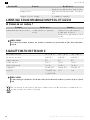
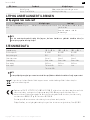
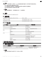
5.TECHNICAL DATA
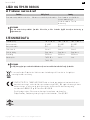
Power supply 120 V 60 Hz 220 V 60 Hz 230 V 50 Hz
Operating temperature 0° to 60° C 0° to 60° C 0° to 60° C
Index protection rating IP31 IP31 IP31
Safety level Class II Class II Class II
Power wiring Open leads Open leads Open leads
Datas wiring RJ45 Male RJ45 Male RJ45 Male
Duty cycle Time ON: 40 s
Time OFF: 60 s
4 min. 4 min.
NOTICE
For additional information on the technical data for this drive, contact your Somfy representative.
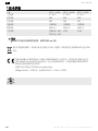
We care about our environment. Do not dispose of the appliance with usual household waste. Give it to an
approved collection point for recycling.
SOMFY ACTIVITES SA, 74300 CLUSES FRANCE as manufacturer hereby declares that the drive covered by
these instructions when marked for input voltage 230V~50Hz and used as intended according to these
instructions, is in compliance with the essential requirements of the applicable European Directives and in
particular of the Machinery Directive 2006/42/EC and EMC Directive 2014/30/EU.
The full text of the EU declaration of conformity is available at www.somfy.com/ce.
Philippe Geoffroy, Approval manager, acting on behalf of Activity director, Cluses, 05/2021.

Sonesse 40 RS485 EN
Copyright© 2021 SOMFY ACTIVITES SA. All rights reserved. 9
Somfy limited, Yeadon LS19 7ZA UK hereby declares that the drive covered by these instructions when
marked for input voltage 230V~50Hz and used as intended according to these instructions, is in compliance
with UK legislation of Machinery safety regulations S.I.2008 N°1597. The full text of the UKCA declaration of
conformity is available at www.somfy.co.uk.
Steven MONTGOMERY, Managing Director Somfy Ltd UK & Ireland, Yeadon, 05/2021.

DE Sonesse 40 RS485
10 Copyright© 2021 SOMFY ACTIVITES SA. All rights reserved.
ÜBERSETZTE ANLEITUNG
Diese Anleitung gilt für alle Antriebe vom Typ Sonesse 40 RS485, deren Ausführungen im aktuellen Katalog zu finden sind.
INHALTSVERZEICHNIS
1.
Vorbemerkungen..........................................................................................................................................................
10
1.1.
Bestimmungsgemäße Verwendung ..............................................................................................................
10
1.2.
Haftung.............................................................................................................................................................
11
2.
Installation.....................................................................................................................................................................
11
2.1.
Montage ...........................................................................................................................................................
11
2.2.
Verkabelung.....................................................................................................................................................
13
2.3.
Inbetriebnahme ...............................................................................................................................................
14
2.4.
Tipps und Empfehlungen für die Installation ...............................................................................................
14
3.
Bedienung und Wartung ..............................................................................................................................................
15
3.1.
Verwendung.....................................................................................................................................................
15
3.2.
PROG-Taste ....................................................................................................................................................
15
3.3.
LED-Anzeigen..................................................................................................................................................
15
4.
Ratschläge und Tipps für den Betrieb.........................................................................................................................
16
4.1.
Fragen zum Antrieb?.......................................................................................................................................
16
5.
Technische Daten .........................................................................................................................................................
16
ALLGEMEINES
Sicherheitshinweise
GEFAHR
Weist auf eine Gefahr hin, die sofort zu schweren bis tödlichen Verletzungen führt.
WARNUNG
Weist auf eine Gefahr hin, die zu schweren bis tödlichen Verletzungen führen kann.
VORSICHT
Weist auf eine Gefahr hin, die zu leichten bis mittelschweren Verletzungen führen
kann.
ACHTUNG
Weist auf eine Gefahr hin, die das Produkt beschädigen oder zerstören kann.
1.VORBEMERKUNGEN
1.1.Bestimmungsgemäße Verwendung
Sonesse 40-Antriebe wurden zur Motorisierung von Innenfensterbehängen jeglicher Art konzipiert, mit Ausnahme von
Klappläden.

Sonesse 40 RS485 DE
Copyright© 2021 SOMFY ACTIVITES SA. All rights reserved. 11
Der Installateur muss ein Fachmann für Gebäudeautomation sein und sicherstellen, dass der Behang gemäß den im
Installationsland geltenden Normen, zum Beispiel EN 13120 zu Innenjalousien, installiert wird.
1.2.Haftung
Lesen Sie bitte diese Anleitung sorgfältig durch, bevor Sie den Antrieb montieren und in Betrieb nehmen.
Beachten Sie außer den Anweisungen in dieser Anleitung auch die Hinweise im beiliegenden Dokument Sicherheitshinweise.
Der Antrieb muss von einer fachlich qualifizierten Person (Elektrofachkraft nach DIN VDE 1000-10) für Antriebe
und Automatisierungen im Haustechnikbereich entsprechend den Somfy-Anweisungen und den geltenden
Vorschriften im Land der Inbetriebnahme installiert werden.
Jede Verwendung des Antriebs außerhalb des oben beschriebenen Anwendungsbereichs ist untersagt. Für Schäden und
Mängel, die durch nicht bestimmungsgemäße Verwendung oder Nichtbeachtung der Anweisungen und Hinweise in dieser
Anleitung und der beigefügten Sicherheitshinweise entstehen, ist die Haftung und Gewährleistung durch Somfy
ausgeschlossen.
Der Installateur hat seine Kunden auf die Betriebs- und Wartungsbedingungen des Antriebs hinzuweisen und ihnen die
Betriebs- und Wartungsanweisungen sowie das beiliegende Dokument Sicherheitshinweise nach Abschluss der Installation
des Antriebs auszuhändigen. Gegebenenfalls erforderliche Kundendiensteingriffe am Antrieb sind von einer fachlich
qualifizierten Person (Elektrofachkraft nach DIN VDE 1000-10) für Antriebe und Automatisierungen im Haustechnikbereich
durchzuführen.
Vor der Installation muss die Kompatibilität dieses Produkts mit den dazugehörigen Ausrüstungs- und Zubehörteilen
geprüft werden. Bei Fragen zur Installation dieses Produkts und für weiterführende Informationen wenden Sie sich bitte an
Ihren Somfy-Ansprechpartner, oder besuchen Sie unsere Website www.somfy.com.
2.INSTALLATION
WARNUNG
•
Diese Anweisungen sind von der fachlich qualifizierten Person für Antriebe und Automatisierungen im
Haustechnikbereich, die den Antrieb installiert, unbedingt einzuhalten.
•
Gültige Normen und Vorschriften sind bei der Montage zu berücksichtigen.
ACHTUNG
•
Den Antrieb nicht fallen lassen, keinen Stößen aussetzen, nicht anbohren, nicht in Wasser tauchen.
•
Installieren Sie für jeden Antrieb eine eigene Bedieneinheit.
•
Für einen möglichst geräuscharmen Betrieb müssen die Abstände zwischen Antrieb, Zubehör, Welle und
Wellenendstück möglichst klein sein.
2.1.Montage
2.1.1.Kopfabdeckung durch eine andere Farbe ersetzen (Optional)
1] Entfernen Sie die Schraube.
2] Ersetzen Sie die Abdeckung durch eine neue Abdeckung.
3] Schrauben Sie die Abdeckung mit 0,4 Nm fest.
HINWEIS
Am Antriebskopf kann je nach Stoff die Abdeckung ausgetauscht werden.

DE Sonesse 40 RS485
12 Copyright© 2021 SOMFY ACTIVITES SA. All rights reserved.
2.1.2.Vorbereitung des Antriebs
üAchten Sie darauf, dass der Innendurchmesser der Antriebswelle mehr als 37 mm
beträgt.
1] Bringen Sie die erforderlichen Zubehörteile zur Integration des Antriebs an der
Welle an: Montieren Sie den Adapter (a) und den Mitnehmer (b) am Antrieb.
a
b
ACHTUNG
Der Adapter muss verpflichtend installiert werden.
2] Messen Sie die Länge (L) zwischen dem Innenrand des Antriebskopfes und
dem äußersten Ende des Mitnehmers.
L
L = …
2.1.3.Vorbereitung der Welle (bei Rundwellen)
1] Schneiden Sie die Welle auf die gewünschte Länge zu, je nach Behang.
2] Entgraten Sie die Welle und entfernen Sie die Späne.
3] Versehen Sie Wellen, die auf der Innenseite glatt sind, mit einer Ausklinkung
mit folgenden Maßen: l = 7 mm, L = 10 mm
1] 2]
2.1.4.Montage von Antrieb/Welle
1] Schieben Sie den Antrieb in die Welle. Positionieren Sie bei Wellen mit glatter
Innenseite die Ausklinkung auf dem Adapter.
2] Der Mitnehmer muss im Inneren der Welle gegen Verschieben gesichert
werden: Entweder durch Befestigung der Welle am Mitnehmer durch 4
selbstschneidende Schrauben mit einem Durchmesser von Ø 5 mm oder
durch 4 Edelstahl-Blindnieten mit einem Durchmesser von Ø 4,8 mm, die
zwischen 5 mm und 15 mm vom äußeren Ende des Mitnehmers entfernt an
der Welle angebracht werden.
1]
2]
L
ACHTUNG
Schrauben bzw. Blindnieten dürfen nur am Mitnehmer angebracht werden, niemals am Antrieb.
2.1.5.Einbau der Wellen-Antriebs-Einheit
ACHTUNG
•
Der Behang darf zwischen den Lagern nicht eingezwängt sein.
•
Kein Kunststoffkreuz ohne den Lageradapter aus Metall verwenden.
Der Antrieb kann direkt am Antriebslager angebracht werden (Abstand der
Schraubenlöcher: 29 mm). Verwenden Sie die 2 Schrauben (4 x 8 mm), die mit dem
Antrieb geliefert werden. Ein manuelles Anzugsmoment von 1,5 Nm ist empfohlen.
Antriebsplatten sind auch im aktuellen Katalog verfügbar (wählen Sie die korrekte
Antriebsplatte für das Lager aus und überprüfen Sie die Drehmomentanforderungen
des Systems). Verwenden Sie die 2 Schrauben (3 x 6 mm), die mit der Antriebsplatte
geliefert werden. Ein manuelles Anzugsmoment von 0,6 Nm ist empfohlen.
1] Schrauben Sie die Adapterhalterung auf den Antriebskopf.
2] Installieren Sie die Wellen-Antriebs-Einheit am Gegenlager (c) und am
Antriebslager (d).
d
c

Sonesse 40 RS485 DE
Copyright© 2021 SOMFY ACTIVITES SA. All rights reserved. 13
ACHTUNG
•
Vergewissern Sie sich, dass die Wellen-Antriebs-Einheit am Gegenlager verriegelt ist. Damit wird verhindert, dass
sich die Wellen-Antriebs-Einheit vom Gegenlager löst.
•
Reduzierter Abstand: Kabel nicht einklemmen und darauf achten, dass sie nicht in Kontakt mit beweglichen Teilen
kommen.
•
Lassen Sie die Antriebswelle nicht auf einer Seite herabhängen.
2.2.Verkabelung
2.2.1.Stromanschluss
VORSICHT
•
Alle Kabel, die durch ein Metallgehäuse geführt werden, müssen mit einer Hülse oder Ummantelung geschützt und
isoliert werden.
•
Befestigen Sie die Kabel so, dass sie nicht in Kontakt zu beweglichen Teilen geraten können.
•
Das Kabel des Antriebs lässt sich nicht abziehen. Wenn es beschädigt wurde, muss der Antrieb zum Kundendienst
gebracht werden.
•
Achten Sie darauf, dass das Stromversorgungskabel des Antriebs zugänglich bleibt: Es muss sich einfach
austauschen lassen.
•
Der Anschluss muss über einen Schaltkasten erfolgen.
1] Unterbrechen Sie die Spannungsversorgung.
2] Schließen Sie den Antrieb gemäß den Tabelleninformationen unten an:
Neutralleiter (N) Phase (L)
120 V 50 Hz Weiß Schwarz
220 V 60 Hz Blau Braun
230 V 50 Hz Blau Braun
OFF
N
L
2.2.2.Anschluss des Netzwerkkabels
ACHTUNG
•
Mit dem Antrieb wurde ein RJ45-Buchse-Buchse-Stecker geliefert, um einfach ein
Verlängerungskabel anschließen zu können.
•
Darauf achten, dass das Kabel während der Installation des Antriebs / der Welle
am Gegenlager nicht eingeklemmt oder beschädigt wird.
Schließen Sie das Netzwerkkabel gemäß den Angaben in den nachstehenden Tabellen
an den Antrieb an.
1 + RS485 5: Nicht verbunden**
2: - RS485 6: Nicht verbunden**
3: Nicht verbunden** 7: Nicht verbunden**
4: Spannungsausgang* 8: ERDE
5
6
7
8
4
3
2
1
* Die Spannungsabschaltungsdaten Endlagenschalters entsprechen den folgenden Spannungs- und Stromwerten: min. 8 V
– max. 50 mA
** Beim Anschluss kann der Antrieb beschädigt werden.
HINWEIS
Der Schaltplan steht zum Download bereit unter: https://www.somfy.com/projects/downloads

DE Sonesse 40 RS485
14 Copyright© 2021 SOMFY ACTIVITES SA. All rights reserved.
2.3.Inbetriebnahme
Der Antrieb hat 2 Jalousienprofile:
Rollomodus (zur Steuerung aller Rollos außer Lamellenjalousien).
Lamellenjalousienmodus.
Zum Einrichten des Antriebs gibt es zwei Tools.
RS485 SETTING TOOL: Das RS485 SETTING TOOL am Antrieb anschließen,
einschalten und den Anweisungen auf dem RS485 SETTING TOOL folgen.
HINWEIS
•
Im Lamellenjalousienmodus können Ausrichtung und Hochfahrposition
gemanagt werden. Im Lamellenjalousienmodus kann der Antrieb nicht mit
dem RS485 SETTING TOOL eingerichtet werden.
•
Achten Sie beim Einstellen der Endlagen darauf, dass das Ausfallprofil in der
oberen Endlage frei bleibt.
SDN Config Tool: Somfy Digital Network Configuration Tool.
HINWEIS
Das SDN Config Tool steht zum Download bereit unter: https://www.somfy.com/projects/downloads
HINWEIS
Die verschiedenen Ausführungen, die im aktuellen Somfy-Katalog zu finden sind.
2.4.Tipps und Empfehlungen für die Installation
2.4.1.Fragen zum Antrieb?
Problem Mögliche Ursachen Lösungen
Der Behang
funktioniert nicht. Die Verkabelung „Power“ (Spannungsversorgung)
oder „Data“ (Netzwerk) ist nicht korrekt. Die Verkabelung überprüfen und ggf. ändern.
Der Überhitzungsschutz des Antriebs wurde
ausgelöst. LED rot = EIN, dann LEDs AUS. Warten Sie ab, bis der Antrieb abgekühlt ist, bevor
Sie ihn erneut starten.
Berühren Sie den Antrieb nicht:
Verbrennungsgefahr.
Das verwendete Netzwerkkabel ist nicht konform. Prüfen Sie das Netzwerkkabel.
Die Endlagen sind nicht richtig eingestellt. Justieren Sie die Endlagen.
Der Behang
verursacht zu viel
Lärm.
Mitnehmer und Adapter sind nicht für die
verwendete Welle geeignet. Mitnehmer und Adapter ersetzen.
Das Spiel zwischen Antrieb, Zubehör, Welle und
Wellenende ist zu groß. Das Spiel zwischen Antrieb, Zubehör, Welle und
Wellenende muss möglichst reduziert werden.
Der Mitnehmer ist nicht richtig an der Welle
befestigt. Den Mitnehmer richtig an der Welle befestigen.
Die Anlage sitzt zu eng zwischen den Lagern. Einschränkung zwischen den Lagern reduzieren.
Die Länge der Ausklinkung ist nicht für den
verwendeten Antriebshaken oder Adapter
geeignet.
Die Länge der Ausklinkung an den verwendeten
Antriebshaken oder Adapter anpassen.
In der Welle befindet sich Schmutz, vergessene
Schrauben oder anderes. Welle leeren.
Die Umgebungstemperatur liegt nicht im Bereich
der zulässigen Betriebstemperatur. Umgebungstemperatur verändern.

Sonesse 40 RS485 DE
Copyright© 2021 SOMFY ACTIVITES SA. All rights reserved. 15
Problem Mögliche Ursachen Lösungen
Der Behang hält
zu früh oder zu
spät an.
Die Endlagen des Behangs verschieben sich. Stellen Sie die Endlagen neu ein.
Der Behang fällt nicht in die empfohlenen
Gewichtsgrenzen. Die Kompatibilität des Behangs überprüfen.
Wenden Sie sich bitte an Ihren Somfy-
Ansprechpartner oder besuchen Sie
www.somfy.com.
3.BEDIENUNG UND WARTUNG
HINWEIS
Dieser Antrieb muss nicht gewartet werden.
ACHTUNG
•
Zur Gewährleistung der Sicherheit von Menschen und Eigentum sind die Antriebe von Somfy mit einem
Überhitzungsschutz ausgerüstet: Bei einer Überhitzung stoppt dieser den Antrieb.
•
Die wiederholte Aktivierung dieser Schutzvorrichtung kann die Leistung des Antriebs beeinträchtigen.
•
Wenn der Überhitzungsschutz des Antriebs aktiviert wird, überprüfen Sie bitte Ihre Anlage und stellen Sie sicher,
dass der Antrieb für den beabsichtigten Zweck geeignet ist.
•
Bei einer normalen Anlage sollte dieser Schutz nicht ausgelöst werden.
HINWEIS
Wenn für bestimmte Funktionen die Spannung getrennt werden muss, wird die Spannungsunterbrechung nur
registriert, wenn sie länger als 10 Sekunden dauert.
3.1.Verwendung
Näheres zur Steuerung des Antriebs ist der Installationsanleitung der verwendeten Bedieneinheit zu entnehmen.
3.2.PROG-Taste
Steuern Sie den Antrieb im Benutzermodus mit AUF /
Stopp / AB / Stopp Kurz drücken (< 1,5 s)
Knoten-ID im Netzwerk einstellen Bis zur ersten Reaktion drücken (ca. 2 s)
Antrieb auf Werkseinstellungen zurücksetzen Bis zur dritten Reaktion drücken (ca. 12 s)
3.3.LED-Anzeigen
LED-Farben Bedeutung Mögliche Ursachen
Grün LEDs leuchten durchgehend für 2 Sekunden bei
Power ON. Spannung ist zugeschaltet.
Blinkt 5 Mal. Validierungseinstellung ist abgeschlossen.
LEDs ein, dann LEDs kurz aus. Bus-Kommunikation. (Kann durch SDN-Befehl
deaktiviert werden.)
Orange LEDs leuchten durchgehend. Antrieb nicht eingestellt.
Blinkt 2 Mal. Knoten-ID an SDN-Netzwerk senden.
Rot LEDs leuchten durchgehend. Der Antrieb hat ein Hindernis erfasst.
LEDs ein, dann LEDs aus. Adapter dreht nicht.
Warten Sie ab, bis der Antrieb abgekühlt ist, bevor
Sie ihn erneut starten.

DE Sonesse 40 RS485
16 Copyright© 2021 SOMFY ACTIVITES SA. All rights reserved.
LED-Farben Bedeutung Mögliche Ursachen
Berühren Sie den Antrieb nicht:
Verbrennungsgefahr.
Blinkt 2 Mal. Der Antrieb ist in einer Position außerhalb der
Endlagen.
Blinkt 3 Mal im Dreiertakt. Einstellung ist nicht möglich.
4.RATSCHLÄGE UND TIPPS FÜR DEN BETRIEB
4.1.Fragen zum Antrieb?
Problem Mögliche Ursachen Lösungen
Der Behang funktioniert nicht. Der Überhitzungsschutz des Antriebs
wurde ausgelöst. Warten Sie ab, bis der Antrieb abgekühlt
ist, bevor Sie ihn erneut starten.
Berühren Sie den Antrieb nicht:
Verbrennungsgefahr.
HINWEIS
Wenn das Produkt weiterhin nicht funktioniert, wenden Sie sich bitte an einen Fachmann für Gebäudeautomation.
5.TECHNISCHE DATEN
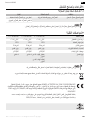
Netzstromversorgung 120 V 60 Hz 220 V 60 Hz 230 V 50 Hz
Temperaturbereich 0° bis 60° C 0° bis 60° C 0° bis 60° C
Schutzart IP31 IP31 IP31
Schutzklasse Klasse II Klasse II Klasse II
Stromanschluss Offene Kabel Offene Kabel Offene Kabel
Anschluss des Netzwerkkabels RJ45 Stecker RJ45 Stecker RJ45 Stecker
Pflichtzyklus Zeit EIN: 40 s
Zeit AUS: 60 s
4 Min. 4 Min.
HINWEIS
Für weitere Informationen zu den technischen Daten des Antriebs wenden Sie sich bitte an Ihren Somfy-
Ansprechpartner.
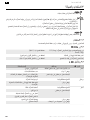
Wir wollen die Umwelt schützen. Entsorgen Sie das Produkt nicht mit dem Hausmüll. Geben Sie es bei einer
zugelassenen Recycling-Sammelstelle ab.

Sonesse 40 RS485 DE
Copyright© 2021 SOMFY ACTIVITES SA. All rights reserved. 17
SOMFY ACTIVITES SA, F74300 CLUSES, FRANKREICH, erklärt hiermit als Hersteller, dass der in dieser
Anleitung beschriebene Antrieb, der gemäß Kennzeichnung auf eine Versorgungsspannung mit 230 V/50 Hz
ausgelegt ist, bei bestimmungsgemäßem Einsatz die grundlegenden Anforderungen der geltenden
europäischen Richtlinien und insbesondere der Maschinenrichtlinie 2006/42/EG sowie der EMV-Richtlinie
2014/30/EU erfüllt.
Der vollständige Text der EU-Konformitätserklärung ist unter der Internetadresse www.somfy.com/ce
verfügbar.
Philippe Geoffroy, Bevollmächtigter für Gerätekonformität, in Vertretung des Geschäftsbereichsleiters,
Cluses, Frankreich, 05/2021.

FR Sonesse 40 RS485
18 Copyright© 2021 SOMFY ACTIVITES SA. All rights reserved.
NOTICE TRADUITE
Cette notice s'applique à toutes les motorisations Sonesse 40 RS485 dont les déclinaisons sont disponibles au catalogue en
vigueur.
SOMMAIRE
1.
Informations préalables...............................................................................................................................................
18
1.1.
Domaine d’application....................................................................................................................................
18
1.2.
Responsabilité..................................................................................................................................................
19
2.
Installation.....................................................................................................................................................................
19
2.1.
Assemblage ......................................................................................................................................................
19
2.2.
Câblage .............................................................................................................................................................
21
2.3.
Mise en service ................................................................................................................................................
22
2.4.
Astuces et conseils d’installation...................................................................................................................
22
3.
Utilisation et maintenance...........................................................................................................................................
23
3.1.
Utilisation.........................................................................................................................................................
23
3.2.
Bouton PROG..................................................................................................................................................
23
3.3.
États des DEL ...................................................................................................................................................
23
4.
Astuces et conseils d’utilisation..................................................................................................................................
24
4.1.
Des questions sur la motorisation ?..............................................................................................................
24
5.
Caractéristiques techniques ........................................................................................................................................
24
GÉNÉRALITÉS
Consignes de sécurité
DANGER
Signale un danger entraînant immédiatement la mort ou des blessures graves.
AVERTISSEMENT
Signale un danger susceptible d’entraîner la mort ou des blessures graves.
PRÉCAUTION
Signale un danger susceptible d’entraîner des blessures légères ou moyennement
graves.
ATTENTION
Signale un danger susceptible d’endommager ou de détruire le produit.
1.INFORMATIONS PRÉALABLES
1.1.Domaine d’application
Les motorisations Sonesse 40 sont conçues pour motoriser tous types de stores d’intérieur à l’exception des pantographes.

Sonesse 40 RS485 FR
Copyright© 2021 SOMFY ACTIVITES SA. All rights reserved. 19
L’installateur, professionnel de la motorisation et de l’automatisation de l’habitat, doit s’assurer que l’installation du produit
motorisé respecte les normes en vigueur dans le pays d’utilisation, notamment la norme EN 13120 relative aux stores
d’intérieur.
1.2.Responsabilité
Avant d’installer et d’utiliser la motorisation, lire attentivement cette notice.
Outre les consignes de cette notice, respecter également les consignes détaillées dans le document joint Consignes de
sécurité.
La motorisation doit être installée par un professionnel de la motorisation et de l’automatisation de l’habitat,
conformément aux consignes de Somfy et à la réglementation applicable dans le pays de mise en service.
Toute utilisation de la motorisation hors du domaine d’application décrit ci-dessus est interdite. Elle exclurait, comme tout
irrespect des consignes figurant dans cette notice et dans le document joint Consignes de sécurité, toute responsabilité et
garantie de Somfy.
Après l’installation de la motorisation, l’installateur doit informer ses clients des conditions d’utilisation et de maintenance de
la motorisation et doit leur transmettre les consignes d’utilisation et de maintenance, ainsi que le document joint Consignes
de sécurité. Toute opération de Service Après-Vente sur la motorisation nécessite l’intervention d’un professionnel de la
motorisation et de l’automatisation de l’habitat.
Avant toute installation, vérifier la compatibilité de ce produit avec les équipements et accessoires associés. Si un doute
apparaît lors de l’installation de ce produit et / ou pour obtenir des informations complémentaires, consulter un
interlocuteur Somfy ou aller sur le site www.somfy.com.
2.INSTALLATION
AVERTISSEMENT
•
Consignes à suivre impérativement par le professionnel de la motorisation et de l’automatisation de l’habitat
réalisant l’installation de la motorisation.
•
Se conformer aux normes et à la législation en vigueur dans le pays d’installation.
ATTENTION
•
Ne jamais laisser tomber, choquer, percer, immerger la motorisation.
•
Installer un point de commande individuel pour chaque motorisation.
•
Pour optimiser le fonctionnement silencieux, les jeux entre la motorisation, les accessoires, le tube et l’embout du
tube doivent être minimisés.
2.1.Assemblage
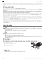
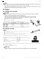
2.1.1.Remplacement du cache de la tête de la motorisation par une autre
couleur (facultatif)
1] Retirer la vis.
2] Remplacer le cache par un autre.
3] Visser le cache à un couple de 0,4 N·m.
INFORMATION
Le cache de la tête peut être changé pour s'adapter au coloris du tissu.

FR Sonesse 40 RS485
20 Copyright© 2021 SOMFY ACTIVITES SA. All rights reserved.
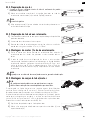
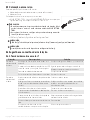
2.1.2.Préparation de la motorisation
üS’assurer que le diamètre intérieur du tube du produit motorisé est supérieur à 37
mm.
1] Monter les accessoires nécessaires à l’intégration de la motorisation dans le
tube d’enroulement : monter la couronne (a) et la roue (b) sur la motorisation.
a
b
ATTENTION
La couronne est obligatoire.
2] Mesurer la longueur (L) entre le bord intérieur de la tête de la motorisation et
l’extrémité de la roue.
L
L = …
2.1.3.Préparation du tube
1] Couper le tube d’enroulement à la longueur désirée en fonction du produit
motorisé.
2] Ébavurer le tube d’enroulement et éliminer les copeaux.
3] Pour les tubes d’enroulement lisses à l’intérieur, découper une encoche selon
les cotes suivantes : l = 7 mm, L = 10 mm.
1] 2]
2.1.4.Assemblage motorisation-tube
1] Glisser la motorisation dans le tube d’enroulement. Pour les tubes
d’enroulement lisses à l’intérieur, positionner l’encoche découpée sur la
couronne.
2] La roue doit être bloquée en translation pour éviter tout mouvement dans le
tube d’enroulement : cela peut être réalisé en fixant le tube d’enroulement sur
la roue à l’aide de 4 vis Parker Ø 5 mm ou 4 rivets pop acier Ø 4,8 mm placés
entre 5 mm et 15 mm de l’extrémité extérieure de la roue, quel que soit le tube
d’enroulement.
1]
2]
L
ATTENTION
Les vis ou les rivets pop ne doivent pas être fixés sur la motorisation mais uniquement sur la roue.
2.1.5.Montage de l’ensemble motorisation-tube
ATTENTION
•
Le produit motorisé ne doit pas être comprimé entre les supports.
•
Ne pas utiliser la croix en plastique sans l'adaptateur de support métallique.
La motorisation peut être fixée directement sur son support (les orifices des vis sont
espacés de 29 mm). Utiliser 2 vis (4 x 8 mm) fournies avec le moteur. Couple de
serrage manuel recommandé : 1,5 N·m.
Des platines d'entraînement sont également disponibles au catalogue en vigueur
(sélectionner la platine correspondant au support et vérifier les contraintes de couple
dans le système). Utiliser les 2 vis 3 x 6 mm fournies avec la platine d'entraînement.
Couple de serrage manuel recommandé : 0,6 N·m.
1] Visser l’adaptateur du support sur la tête de la motorisation.
2] Installer et fixer l’ensemble motorisation-tube sur le support embout (c) et sur
le support motorisation (d).
d
c
La pagina si sta caricando...
La pagina si sta caricando...
La pagina si sta caricando...
La pagina si sta caricando...
La pagina si sta caricando...
La pagina si sta caricando...
La pagina si sta caricando...
La pagina si sta caricando...
La pagina si sta caricando...
La pagina si sta caricando...
La pagina si sta caricando...
La pagina si sta caricando...
La pagina si sta caricando...
La pagina si sta caricando...
La pagina si sta caricando...
La pagina si sta caricando...
La pagina si sta caricando...
La pagina si sta caricando...
La pagina si sta caricando...
La pagina si sta caricando...
La pagina si sta caricando...
La pagina si sta caricando...
La pagina si sta caricando...
La pagina si sta caricando...
La pagina si sta caricando...
La pagina si sta caricando...
La pagina si sta caricando...
La pagina si sta caricando...
La pagina si sta caricando...
La pagina si sta caricando...
La pagina si sta caricando...
La pagina si sta caricando...
La pagina si sta caricando...
La pagina si sta caricando...
La pagina si sta caricando...
La pagina si sta caricando...
La pagina si sta caricando...
La pagina si sta caricando...
La pagina si sta caricando...
La pagina si sta caricando...
La pagina si sta caricando...
La pagina si sta caricando...
La pagina si sta caricando...
La pagina si sta caricando...
La pagina si sta caricando...
La pagina si sta caricando...
La pagina si sta caricando...
La pagina si sta caricando...
La pagina si sta caricando...
La pagina si sta caricando...
La pagina si sta caricando...
La pagina si sta caricando...
La pagina si sta caricando...
La pagina si sta caricando...
La pagina si sta caricando...
La pagina si sta caricando...
La pagina si sta caricando...
La pagina si sta caricando...
La pagina si sta caricando...
La pagina si sta caricando...
La pagina si sta caricando...
La pagina si sta caricando...
La pagina si sta caricando...
La pagina si sta caricando...
La pagina si sta caricando...
La pagina si sta caricando...
La pagina si sta caricando...
La pagina si sta caricando...
La pagina si sta caricando...
La pagina si sta caricando...
La pagina si sta caricando...
La pagina si sta caricando...
La pagina si sta caricando...
La pagina si sta caricando...
La pagina si sta caricando...
La pagina si sta caricando...
La pagina si sta caricando...
La pagina si sta caricando...
La pagina si sta caricando...
La pagina si sta caricando...
La pagina si sta caricando...
La pagina si sta caricando...
La pagina si sta caricando...
La pagina si sta caricando...
La pagina si sta caricando...
La pagina si sta caricando...
La pagina si sta caricando...
La pagina si sta caricando...
La pagina si sta caricando...
La pagina si sta caricando...
La pagina si sta caricando...
La pagina si sta caricando...
-
 1
1
-
 2
2
-
 3
3
-
 4
4
-
 5
5
-
 6
6
-
 7
7
-
 8
8
-
 9
9
-
 10
10
-
 11
11
-
 12
12
-
 13
13
-
 14
14
-
 15
15
-
 16
16
-
 17
17
-
 18
18
-
 19
19
-
 20
20
-
 21
21
-
 22
22
-
 23
23
-
 24
24
-
 25
25
-
 26
26
-
 27
27
-
 28
28
-
 29
29
-
 30
30
-
 31
31
-
 32
32
-
 33
33
-
 34
34
-
 35
35
-
 36
36
-
 37
37
-
 38
38
-
 39
39
-
 40
40
-
 41
41
-
 42
42
-
 43
43
-
 44
44
-
 45
45
-
 46
46
-
 47
47
-
 48
48
-
 49
49
-
 50
50
-
 51
51
-
 52
52
-
 53
53
-
 54
54
-
 55
55
-
 56
56
-
 57
57
-
 58
58
-
 59
59
-
 60
60
-
 61
61
-
 62
62
-
 63
63
-
 64
64
-
 65
65
-
 66
66
-
 67
67
-
 68
68
-
 69
69
-
 70
70
-
 71
71
-
 72
72
-
 73
73
-
 74
74
-
 75
75
-
 76
76
-
 77
77
-
 78
78
-
 79
79
-
 80
80
-
 81
81
-
 82
82
-
 83
83
-
 84
84
-
 85
85
-
 86
86
-
 87
87
-
 88
88
-
 89
89
-
 90
90
-
 91
91
-
 92
92
-
 93
93
-
 94
94
-
 95
95
-
 96
96
-
 97
97
-
 98
98
-
 99
99
-
 100
100
-
 101
101
-
 102
102
-
 103
103
-
 104
104
-
 105
105
-
 106
106
-
 107
107
-
 108
108
-
 109
109
-
 110
110
-
 111
111
-
 112
112


in altre lingue
- français: Somfy sonesse 40 Mode d'emploi
- español: Somfy sonesse 40 Instrucciones de operación
- Nederlands: Somfy sonesse 40 Handleiding
- português: Somfy sonesse 40 Instruções de operação
- dansk: Somfy sonesse 40 Betjeningsvejledning
Documenti correlati
-
Somfy ROLL UP 28 WIREFREE Istruzioni per l'uso
-
Somfy LS 40 Instructions Manual
-
-
-
-
Somfy LT 60 PA Manuale del proprietario
-
-
-
-