
AUTOMATIC SATELLITE DISH
AUTOMATISCHE SATELLITENANTENNE
ANTENNA SATELLITARE AUTOMATICA
INSTALLATION AND USE MANUAL
GEBRAUCHS-UND INSTALLATIONSHANDBUCH
MANUALE PER L’USO E PER L’INSTALLAZIONE
ASR 680 / 1P / PLUS / DF /DF PLUS
ASR 800 / 1P / PLUS / DF /DF PLUS
GB
D
IT

2
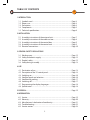
TABLE OF CONTENTS
1 INTRODUCTION
1.1 Symbols used .......................................................................................................... Page 3
1.2 Proper use ................................................................................................................ Page 3
1.3 Description ............................................................................................................. Page 4
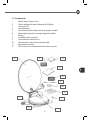
1.4 Components ............................................................................................................ Page 5
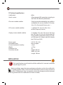
1.5 Technical specications....................................................................................... Page 6
2 INSTALLATION
2.1 Assembly instructions of the external unit .................................................. Page 7
2.2 Assembly instructions of the cable run box ............................................... Page 8
2.3 Assembly instructions of the control box .................................................... Page 9
2.4 Assembly instructions of the control unit .................................................... Page 9
2.5 Electrical connections .......................................................................................... Page 10
3 GENERAL SAFETY REGULATIONS
3.1 Working area ........................................................................... ............................... Page 12
3.2 Safety and electric supply .................................................................................. Page 12
3.3 People’s safety ........................................................................................................ Page 12
3.4 Safety during assembly ....................................................................................... Page 13
4 USE
4.1 Destination of use ................................................................................................ Page 13
4.2 Description of the 1P control panel ...................................... ......................... Page 14
4.3 Switching on ........................................................................................................... Page 16
4.4 Satellite search and selection ........................................................................... Page 16
4.5 Satellite dish parking ............................................................................................ Page 17
4.6 Switching o ........................................................................................................... Page 17
4.7 Programming the display languages ............................................................. Page 18
4.8 Special notes ........................................................................................................... Page 18
5 DISPOSAL .......................................................................................................................... Page 19
6 INFORMATION
6.1 Service ....................................................................................................................... Page 19
6.2 Warranty ................................................................................................................... Page 20
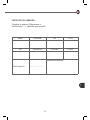
6.3 Manufacturer’s declaration of conformity .................................................... Page 21
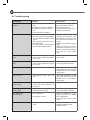
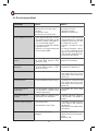
6.4 Troubleshooting .................................................................................................... Page 22
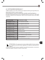
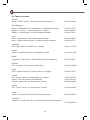
6.5 Service centers ....................................................................................................... Page 24
0

3
GB
INTRODUCTION
1
Congratulations on buying this ASR satellite dish with automatic tracking. This
is a technologically advanced and high quality product for satellite TV recep-
tion in vehicles.
Before installing and operating the, satellite system examine carefully the functions of the
device and its proper use.
Carefully read this use manual and always keep it close to the device for quick and easy
reference. If the device is transferred to a third party, do not forget to pass on all the neces-
sary documents.
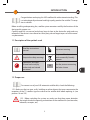
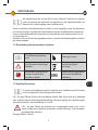
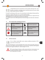
1.1 Description of the symbols used
Read the instructions
manual Important warning
Keep to the safety warnings
Dispose of the device in an
environmentally friendly
manner
Operations to be per-
formed exclusively by
authorised and trained
personnel
See the picture concerning
the letter shown
A
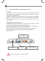
1.2 Proper use
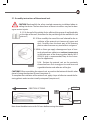
For correct use of your ASR automatic satellite dish, check the following:
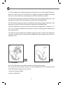
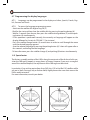
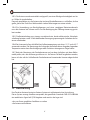
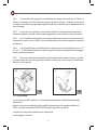
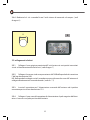
1.2.1 Make sure that no trees, walls, buildings or other objects that may compromise the
reception of the TV satellite signal are close to the satellite dish before opening it. (see
pictures 1A and 1B )
1.2.2. Before switching the system on, make sure that there areno obstacles
that might hinder the opening and rotation of the satellite dish (tree branches,
balconies, canopies, etc)

4
1.2.3 The satellite dish has been designed and tested to resist a wind speed of 120 km/h.
However, in the case of very strong wind, we suggest you keep the satellite dish closed
because its wide surface may cause damage stress to the roof of your vehicle.
1.2.4 The battery voltage must always be sucient; if the supply voltage is lower than 10V,
the electronic safety circuit will prevent the satellite dish from being lifted.
1.2.5 The battery voltage must always be sucient; if the supply voltage is lower than 10V,
the electronic safety circuit will prevent the satellite dish from being lifted.
1.2.6 The satellite dish must be used only if the external temperature is between -15°C
and + 45°C. Using the satellite dish outside these values may damage the satellite dish or
cause malfunctions.
1.2.7 After using the satellite dish and before moving o, make sure that the satellite dish
is closed. In any case, do not move until the audible signal that indicates that the dish is
parked turns o.
NO OK
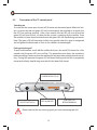
1.3 Description
Your ASR satellite dish uses a totally automatic satellite tracking system.
This system can track satellites that give a signal modulated in QPSK, according to the
DVB-SI EN 300 468 Standard, and can hence:
• search the selected satellite
• park the satellite dish
1A 1B

5
GB
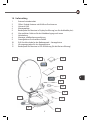
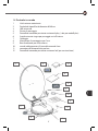
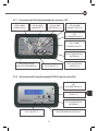
1.4 Components
1 Motor-driven external unit
2 Oset satellite dish with a diameter of 65-80 cm
3 Universal LNB
4 Assembly plate
5 User control panel, display version (only plus models)
6 Watertight box for the inside passage of the cables
7 Wiring
8 Assembly and use manual
9 Control box for external unit
10 Control panel – box rj45 connection cable
11 Box power connector
12 LED version user control panel (for the basic version)
2 5 6
8
12
10
9
11
1
4
7
3

6
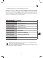
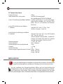
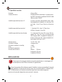
1.5 Technical specications
• Satellite dish oset
• Search system fully automatic NID recognition according to
the DVB-SI EN 300 468 specications
• IP version settable satellites Only the manufactured default set satellite is
available for this version (Hot Bird 13E in Italy,
Astra 19 in France and Germany etc…)
• LED version settable satellites 7 ( Hotbird 13E , Astra 19, Thor, Sirius
Atl. Bird, Hispasat, Astra 28).
• Display version settable satellites 15 (Hotbird 13E, Astra 19E, Astra 28E, Euro
bird 16E, Thor 1W, Sirius 5E, Atlantic Bird 5W,
Hispasat 30W, Eurobird 9E, Eutelsat 7E, Eutel-
sat 10E,Amos 3W, Atlantic bird 8W, Atlantic
bird 12W, Astra 23,5E)
• Power supply 12V DC -20 + 30%
• Absorbed current Max 4 Ampere
• Current absorbed in stand-by ≤ 5mA
• Weight ≤ 12 kg
• Protection fuse 5A
• Size (when closed) height: 190 mm
Width: 618 mm
Length: 766 mm
2
INSTALLATION
Only specialised personnel should install the satellite dish. Incorrect installation
may damage the system.
Before installation, open the carton packaging and make sure that the satellite dish
is in good condition. Make sure that all parts described in the instruction manual are
present. (SR Mecatronic does not accept any claims for damage caused by transport
or missing material after the satellite dish has been installed).

7
GB
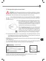
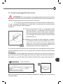
2.1 Assembly instructions of the external unit
CAUTION! Read carefully the safety standards concerning installation before in-
stalling the device. The non-observance of these instructions may lead to dam-
age or serious injuries.
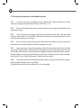
2.1.1 On the roof of the vehicle, nd a suciently large area of roof (preferably
at the sides of the roof) that allows for the positioning of the satellite dish (see
picture 2 )
2.1.2 Clean carefully the area of the roof selected for the in-
stallation of the external unit (remove oil, grease and
dust). Carefully clean the lower part of the fastening
plate in order to remove any trace of dust and grease.
2.1.3 With a silicon gun apply a homogenous layer of struc-
tural polyurethane adhesive at ambient temperature
in the lower part of the fastening plate (dekasyl MS-2
OR MS-5 glue is recommended; keep to the instruc-
tions for application).
2.1.4 Position the external unit on the previously
cleaned roof area. Push strongly on it in order to ensure
a good distribution and adhesion of the glue.
CAUTION!!! When assembling the external unit, ensure that the bottom of the dish when
closed is facing the direction of travel (see picture 3)
To complete the installation of the external unit, apply a layer of adhesive around the fas-
tening plate in order to make it totally waterproof (see picture 4)
2
DIRECTION OF TRAVEL
Note: leave the adhesive to set for 24 hours before moving the vehicle
GLUE
ROOF
3
4

8
2.2 Assembly instructions of the cable run box
2.2.1 For easy and quick installation of the satellite dish, nd a position on the roof
where the supply and control box will be installed (see 2.3.1) .
2.2.2 With a 20 diameter hole cutter make a hole for the passage of the cables inside
the vehicle’s cabin.
2.2.3 Clean and remove any grease from the surface around the hole. Take the cable
box and make a hole in it so the M25 cable (which includes the sat cable and the internal
connection cable) can pass through.
2.2.4 Run the cables inside, through the hole previously made in the roof and x the
cable rmly to the cable box with the bolt (supplied in the kit).
2.2.5 Apply a generous layer of polyurethane adhesive on the base of the box (use the
same type as that used for the fastening of the external unit). Position the box on the roof
close to the hole and press in order to ensure a good distribution and adhesion of the glue.
Run the cables securely along the roof (insert them into a cable channel in order to protect
them from UV rays) and bring the excess cables into the camper.
2.2.6 The cables must be fastened to the roof in order to prevent them from moving or
being caught by objects such as branches.
The external assembly of the satellite dish is now complete.

9
GB
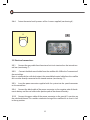
2.3.1 Find a place inside the vehicle that is easily accessible to the user, preferably near
the TV or inside a cupboard.
2.3.2 Position and fasten the wall box inside this accessible and ventilated area so that
any service operations can be performed easily and quickly (see picture 5).
CAUTION! The ventilation of the device is important because it avoids overheating
of the components.
2.4 Assembly instructions of the internal control unit for LED and Plus versions
2.4.1 Find an area inside the vehicle that is easily accessible and visible from a distance
less than 2 metres from the control box (i.e. the length of the connection cable between
the box and control panel).
2.4.2 Use a hole cutter with a 15mm diameter to make a through hole at the point se-
lected for the assembly (see drawing 6).
2.4.3 Run the RJ45 patch cat6 connection cable supplied with the satellite dish and
connect the box to the internal control unit (see drawing7/7.1).
5
It is advisable to fasten the box
onto the wall with two screws. It
should be fastened vertically and
positioned either to the right or
left of the TV.
2.3 Assembly instructions of the control box

10
15
2.4.4 Fasten the control unit by means of the 4 screws supplied (see drawing 6 ).
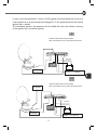
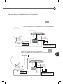
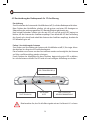
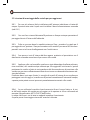
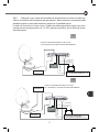
2.5 Electrical connections
2.5.1 Connect the grey cable from the external unit to its terminals on the internal con-
trol box (see drawing 7).
2.5.2 Connect the black coaxial cable from the satellite dish LNB to the F connector of
the control box.
Note: in satellite dishes with dual output, the second black coaxial cable from the satellite
dish must be directly connected to the second receiver (see drawing 7.1).
2.5.3 Insert the power connector supplied with the system into the special connector
on the control box.
2.5.4 Connect the black cable of the power connector to the negative pole of the do-
mestic battery and the red cable to the positive pole of the domestic battery.
2.5.5 Connect the green cable of the power connector to the special D+ position on
the vehicle dashboard. This enables automatic closing of the satellite dish in case it is left
in the up position.
6

11
GB
DECODER 2
GREEN CABLE
GREEN CABLE
BLACK CABLE
BLACK CABLE
RED CABLE
RED CABLE
WIRING DIAGRAM, ONEOUTPUT VERSION
NOTE: THE DECODER AND ITS CABLE ARE NOT INCLUDED
WIRING DIAGRAM, ONEOUTPUT VERSION
NOTE: THE DECODER AND ITS CABLE ARE NOT INCLUDED
TO THE IGNITION KEY OF THE
VEHICLE + 12 V CURRENT
TO THE IGNITION KEY OF THE
VEHICLE + 12 V CURRENT
In many cases the connection is on pin 15 of the general terminal board and in any case
it corresponds to an active and positive voltage of +12 VDC generated when the vehicle
ignition key is rotated.
This connection prevents the operation of the satellite dish when the vehicle is moving
or the ignition key is turned for ignition.
7
7.1
DECODER
DECODER 1
7.1

12
GENERAL SAFETY REGULATIONS
3
CAUTION ! Read all the instructions.
The improper or non observance of these instructions may result in serious dam-
age and injuries.
KEEP THESE INSTRUCTIONS
3.1 Working area
Before switching the system on, always make sure that the working area is free
from obstacles (tree branches, protruding balconies etc.).
RISK OF DAMAGE TO SATELLITE DISH AND VEHICLE
3.2 Safety and electric supply
The device must be exclusively powered with 12 V, supplied directly from the service bat-
tery using cables with a minimum section of 2.5 mm.
If a 12V electric power supply is used instead of the battery, make sure that it is stabilised
and able to deliver 3 Amps continuously and 10 Amps for short periods.
Do not use a poor quality battery charger that is not stabilised.
3.3 People’s safety
Before enabling the opening of the satellite dish, make sure that nobody is on
the vehicle roof. If someone is on the roof of the camper, he/she could be hit by
the satellite dish when it is opened or closed.
RISK OF SERIOUS INJURY

13
GB
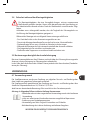
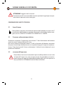
3.4 Safety during assembly
For the assembly operations that imply the risk of fall, the necessary safety pre-
cautions must be adopted: for instance, a work bridge to be used when op-
erating on the vehicle roof. Make sure that the roof of the vehicle has sucient carrying
capacity for the assembly operations.
Moreover, during assembly make sure that :
- The device is disconnected from the electric mains
- The person in charge of the assembly does not suer from vertigo
- The person in charge of the assembly wears non-slip and accident-prevention
shoes.
- Nobody is under the satellite dish during assembly.
- The lifting apparatus is non-slip and dry.
- The bridge and ladder are suciently stable and robust
USE 4
4.1 Destination of use
The satellite dish is manufactured for the reception of digital TV and radio signals from a
satellite only when the vehicle is stationary. The reception unit allows for the reception of
satellite TV and radio signals whose frequency is included between 10.7 GHz. and 12.75
GHz. Any dierent use renders the warranty void.
Caution: SR Mecatronic does not accept any liability for damage caused by:
- Wrong use that does not comply with the intended use of the device
- Repairs not performed by authorised service centres
- Tampering with any mechanical components
- Use of non-original spare parts and ttings
- Non-observance of the instructions in this manual
IN THE ABOVE-MENTIONED CASES THE WARRANTY IS VOID

14
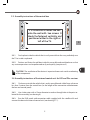
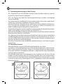
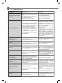
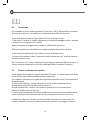
4.2. Description of the 1P control panel
Switching on
To switch on the system press the on/o (3) button on the control panel. When this but-
ton is pressed the red and green LED will simultaneously be switched on to check that
the LEDS are working correctly. After a few seconds the red LED will turn o and the
green LED will start to ash, to show that the system is searching for the satellite. Once
the satellite has been found and conrmed the green LED will stop ashing and remain
xed The green LED will then begin to ash very quickly when the signal is recognized
and will go back to xed mode as soon as the satellite is acknowledged.
Parking/switching o
To park and therefore switch o the satellite dish press the on/o (3) button for a few
seconds until the green LED starts to ash. This procedure must always be carried out
before travelling in order to close the satellite dish and put it back into position for travel-
ling. During this operation the green LED will keep ashing until the dish is completely
closed and will only stop ashing once the dish has been fully closed..
Please note that for any warning signals you must read paragraph 6.4.1
RED ALARM LED
POWER SUPPLY LED (2)
ON/OFF BUTTON (3) USB PLUG FOR
REPROGRAMMING

15
GB
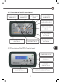
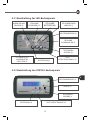
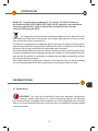
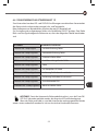
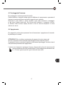
4.2.1 Description of the LED control panel
4.2.2 Description of the DISPLAY control panel
ELEVATION STRESS
ALARM LED (5)
ROTATION ERROR
ALARM LED (5)
BATTERY ALARM
LED (5)
RF CABLE ERROR
ALARM LED (5)
POWER SUPPLY LED (2)
IGNITION ON ALARM
LED (5)
SAT. DISH PARKING
BUTTON (6)
SATELLITE SELECTION
BUTTON (4)
POWER SUPPLY LED (2)
DISPLAY (1)
SATELLITE SEARCH BUTTON (4)ON/OFF BUTTON (3)
ON/OFF BUTTON (3)
SATELLITE INDICATION LED
SELECTED (5)
SAT. DISH
PARK BUTTON (6)

16
4.3 Switching on
Press the on / o (3) button on the control panel.
When the button is pressed, the following LEDs will turn on in the LED version:
- green supply LED (2) showing the supply condition
- green LED (5) for the selected satellite will ash while the system searches for the satellite.
The LED light is green and stays on once the satellite dish has locked on to the satellite.
- the green power LED (2) turns on to show the power condition
- the display shows the name of the selected satellite that the system will automatically
search for.
Note: If the satellite dish is not in the parked position when the power is switched on, the
system will close the satellite dish instead of performing the search.
4.4 Satellite search and selection.
The system starts searching for the previously selected satellite as soon as it is
switched on.
If the satellite shown is not the one you want, press button (4) on the control panel
and:
a) Scroll through the list of stored satellites until you nd the satellite you want (in
the display version)
b) Scroll through the dierent LEDs until the light on the LED of the satellite you
want turns on (LED version).
The system will automatically search for the selected satellite and will store its
position in order to facilitate and speed up subsequent searches.
If the satellite is not able to nd the satellite after performing a full scan, the sys-
tem will set the satellite dish to its parked position.

17
GB
4.5 Satellite dish parking
Press button (6) to park the satellite dish
This operation must be performed before switching the power o and it brings
the satellite dish to its parked and travel position.
If the button controlling this operation is pressed, the green LED starts ashing
and will ash for all the time required for the closure of the satellite dish. The green
LED will turn o when the closure of the dish is complete. In the display version
the message (closure in progress) will appear.
4.6 Switching o
Switch o the satellite dish by pressing the ON / OFF button (3) and holding it for about 5
seconds.
CAUTION !!! Before switching o your satellite system by pressing button (3), make
sure that the satellite dish is in parking position (button 6) .
If you switch o the satellite dish when it is not in the parked position, it will stay
in the position it was before switching it o. The satellite dish will be brought back to its
parked position by turning the vehicle ignition key, provided that the green cable has
been correctly connected with + 12 V generated when the ignition key is turned.

18
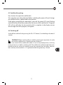
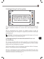
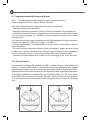
4.7 Programming the display languages
4.7.1 Languages can be programmed in the display are: Italian, Spanish, French, Eng-
lish, German and Dutch.
4.7.2 To access the language programming menu:
- Switch on the satellite dish by pressing ON (3)
- Wait for the start and then close the satellite dish by pressing the parking button (6).
- Wait for 5 seconds from closure, then press the satellite change button (4) and the park-
ing button (6) simultaneously.
- If this operation is performed correctly, the currently set language will appear on the
display, followed by 3 asterisks (ITALIAN ***, for instance)
- Press the satellite change button (4) several times in order to scroll through the menu
until the desired language appears.
- Save the selected language by pressing the parking button (6). 3 dots will appear after a
few seconds, conrming the new language.
- To leave the menu, press the satellite change (4) and parking (6) buttons simultaneously.
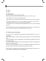
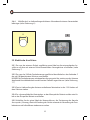
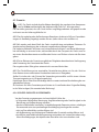
4.8 Special notes
The factory assembly position of the LNB is along the centre axis of the dish and in this po-
sition the LNB works properly in many places in Europe. However, if you are in a marginal
area of the satellite footprint, the adjustment of the LNB angle can be critical.
In particular, if you wish to receive from Astra 28E, Astra 19E or Hot Bird 13E satellites while
you are in Spain, Portugal, Italy or further aeld, slightly loosen the screw that secures the
LNB in order to rotate it.
For more information, consult your dealer.
TURKEY:
HOT BIRD 13 E 2=22°
ASTRA 19 E 2=15°
ASTRA 28 E 2=5°
PORTUGAL
HOT BIRD 13 E 1=25°
ASTRA 19 E 1=28°
ASTRA 28 E 1=37°
MOROCCO:
HOT BIRD 13 E 1=27°
ASTRA 19 E 1=34°
ASTRA 28 E 1=41°
8 8.1
0
01 2

19
GB
In compliance with article 13 of Law Decree n. 151 of 25th July 2005 “implementation
of the 2002/95/EC, 2002/96/EC and 2003/108/EC Directives concerning the reduction
of hazardous materials in electric and electronic devices and of waste disposal”
This symbol means that this device must be disposed of separately from other
waste and not in household waste after its use.
The user must dispose of this device in the special collection centres for electric
and electronic waste, as regulated by the local legislation in force.
The proper selective waste collection, followed by recycling, treatment and eco-compati-
ble disposal of the device, has a positive impact on the environment and health because it
facilitates the re-use and recycling of the materials composing the device.
The illegal disposal of the product by the user implies the administrative sanctions pro-
vided for by the regulations in force.
5
6
DISPOSAL
INFORMATION
6.1 Service
CAUTION ! Only qualied and authorised personnel can repair the device (see
paragraph 5.5 on the service centres). This guarantees that the device is used in
conditions of safety, without running the risk of voiding the warranty and that only
original spare parts are used.

20
6.2 Warranty
6.2.1 The device has a warranty of 3 years from the date of purchase for all its
mechanical parts. For the electronic parts SR Mecatronic warrants that the device
has been manufactured and tested carefully and is therefore free from defects before its
delivery.
6.2.2 Keep the receipt or invoice, which must be shown as a purchase proof for any
service operations under warranty (otherwise the warranty is void).
6.2.3 SR Mecatronic will repair any defects found on this device free of charge in a rea-
sonable time after receiving the device. The necessary costs for this purpose, especially the
work and material costs, will be totally charged to us, while the costs and risks concerning
the transport of the device to the authorised centre will be charged to you.
6.2.4 The operations under warranty do not imply an extension or renewal of the war-
ranty period of the device. The replaced parts become automatically our property.
6.2.5 For any warranty operations we kindly ask you to deliver your device to our au-
thorised service centre. Make sure that the packaging is in perfect conditions for a safe
transport (original packaging). A brief description of the failure must be included and in-
serted in the pack, together with your full address. Moreover, as a proof of warranty right,
do not forget to put your original document of purchase (receipt or invoice) in the pack.
6.2.6 WAIVERS
The warranty does not cover those defects that:
- occur following improper, negligent or careless use or storage of the device;
- are caused by wrong installation, maintenance or repair performed by non authorised -
personnel or by damage caused by transport;
- are not referable to manufacturing defects;
- are caused by the use of non original spare parts and accessories;
- have been caused by lightning, wrong supply voltage or other force majeure events, not
ascribable to the Manufacturer.
La pagina si sta caricando...
La pagina si sta caricando...
La pagina si sta caricando...
La pagina si sta caricando...
La pagina si sta caricando...
La pagina si sta caricando...
La pagina si sta caricando...
La pagina si sta caricando...
La pagina si sta caricando...
La pagina si sta caricando...
La pagina si sta caricando...
La pagina si sta caricando...
La pagina si sta caricando...
La pagina si sta caricando...
La pagina si sta caricando...
La pagina si sta caricando...
La pagina si sta caricando...
La pagina si sta caricando...
La pagina si sta caricando...
La pagina si sta caricando...
La pagina si sta caricando...
La pagina si sta caricando...
La pagina si sta caricando...
La pagina si sta caricando...
La pagina si sta caricando...
La pagina si sta caricando...
La pagina si sta caricando...
La pagina si sta caricando...
La pagina si sta caricando...
La pagina si sta caricando...
La pagina si sta caricando...
La pagina si sta caricando...
La pagina si sta caricando...
La pagina si sta caricando...
La pagina si sta caricando...
La pagina si sta caricando...
La pagina si sta caricando...
La pagina si sta caricando...
La pagina si sta caricando...
La pagina si sta caricando...
La pagina si sta caricando...
La pagina si sta caricando...
La pagina si sta caricando...
La pagina si sta caricando...
La pagina si sta caricando...
La pagina si sta caricando...
La pagina si sta caricando...
La pagina si sta caricando...
La pagina si sta caricando...
La pagina si sta caricando...
La pagina si sta caricando...
La pagina si sta caricando...
La pagina si sta caricando...
La pagina si sta caricando...
La pagina si sta caricando...
La pagina si sta caricando...
-
 1
1
-
 2
2
-
 3
3
-
 4
4
-
 5
5
-
 6
6
-
 7
7
-
 8
8
-
 9
9
-
 10
10
-
 11
11
-
 12
12
-
 13
13
-
 14
14
-
 15
15
-
 16
16
-
 17
17
-
 18
18
-
 19
19
-
 20
20
-
 21
21
-
 22
22
-
 23
23
-
 24
24
-
 25
25
-
 26
26
-
 27
27
-
 28
28
-
 29
29
-
 30
30
-
 31
31
-
 32
32
-
 33
33
-
 34
34
-
 35
35
-
 36
36
-
 37
37
-
 38
38
-
 39
39
-
 40
40
-
 41
41
-
 42
42
-
 43
43
-
 44
44
-
 45
45
-
 46
46
-
 47
47
-
 48
48
-
 49
49
-
 50
50
-
 51
51
-
 52
52
-
 53
53
-
 54
54
-
 55
55
-
 56
56
-
 57
57
-
 58
58
-
 59
59
-
 60
60
-
 61
61
-
 62
62
-
 63
63
-
 64
64
-
 65
65
-
 66
66
-
 67
67
-
 68
68
-
 69
69
-
 70
70
-
 71
71
-
 72
72
-
 73
73
-
 74
74
-
 75
75
-
 76
76


Mecatronic ASR 800 1P Installation and Use Manual
- Tipo
- Installation and Use Manual
- Questo manuale è adatto anche per
in altre lingue
- English: Mecatronic ASR 800 1P
- Deutsch: Mecatronic ASR 800 1P
Altri documenti
-
TechniSat SKYRIDER 65 Single Manuale utente
-
Kathrein UFD 545 Manuale utente
-
-
-
Teleco TEK32DE Televisore Manuale utente
-
-
-