GCE AMBULANCE PANEL II Istruzioni per l'uso
- Tipo
- Istruzioni per l'uso

GCE HEALTHCARE
INSTRUCTION FOR USE
BEDIENUNGSANLEITUNG
AMBULANCE PANEL II
INSTRUKCJA OBSŁUGI
NÁVOD K POUŽITÍ
ИНСТРУКЦИЯ ПО ЭКСПЛУАТАЦИИ
HASZNÁLATI UTASÍTÁS
INSTRUCCIONES DE USO
INSTRUÇÕES DE UTILIZAÇÃO
ANVÄNDARANVISNING
BRUKSANVISNING
BRUGERVEJLEDNING
KÄYTTÖOHJE
EN
DE
CS
RU
HU
FR
ES
PT
IT
SV
NL
NO
DA
FI
PL
GEBRUIKSINSTRUCTIES
MANUEL D´UTILISATION
MANUALE D´USO
HR
EL
NAPUTAK ZA UPORABU
ΟΔΗΓΙΕΣ ΧΡΗΣΕΩΣ

A
A
BCD
E
F
G
G3
G1
G2
2/219
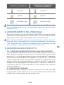
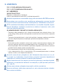
FIG. 1
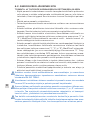
FIG. 2 & FIG. 3

3/219
EN
1. FOREWORD
GCE Ambulance Panels are medical devices classifi ed as class IIb accord-
ing to the Medical Device Directive 93/42/EEC.
Their Compliance with essential requirements of 93/42/EEC Medical De-
vice Directive is based upon EN ISO 1789 standard.
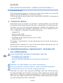
2. INTENDED USE
Ambulance panels are designed for use as an integral part of ambulances.
When connected to the source of medical gas (e.g. regulator, pressure
regulator integrated with cylinder valve) then can be used as a terminal unit
and allow the connection and gas supply of diff erent medical devices, e.g.
fl owmeter, resuscitator, ventilator, suction ejector. They are intended for ad-
ministration of the following medical gases in the treatment, management,
diagnostic, evaluation and care of the patient:
• oxygen O2
• air for breathing AIR
• nitrous oxide N2O
• specifi ed mixtures of the gases listed e.g. O2+N2O
• vacuum VAC
Ambulance panels are not intended for the driving of surgical tools.
Working pressure of Ambulance Panel is from 4 to 5 bar for medical gases
and ≤ 40 kPa (expressed as absolute pressure) for vacuum.
3. OPERATIONAL, TRANSPORT AND STORAGE
SAFETY REQUIREMENTS
Keep the product and its associated equipment away from:
• Heat sources and sun light,
• Flammable materials
• Oil or grease (especially be careful in use of hand cream)
• Water
• Dust
The product and its associated equipment must be prevented from fall-
ing over.
Always maintain oxygen cleanliness standards.
Use only the product and its associated equipment in a well ventilated
area.
ENGLISH
INSTRUCTION FOR USE: AMBULANCE PANEL II

4/219
EN
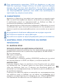
Before initial use, the product should be kept in its original packaging. GCE
recommends the use of the original packaging (including internal sealing
bag and caps) if the product is withdrawn from operation (for transport, stor-
age).
Statutory laws, rules, and regulations for medical gases, accident preven-
tion, and environmental protection must be observed.
OPERATING CONDITIONS STORAGE AND TRANSPORT
+5/+40°C -30/+70°C
10/100% 10/100%
600/1200 mbar 600/1200 mbar
In case of storage at a temperature below +5°C, do not operate the prod-
uct until it has been allowed to increase its temperature to a minimum of
+5°C.
4. PERSONNEL INSTRUCTIONS
The Medical Devices Directive 93/42/EEC states that product provider must
ensure that all personnel handling the product are provided with the opera-
ting instructions & performance data.
Do not use the product without properly familiarization of the product
and its safe operation as defi ned in this Instruction for use. Ensure user is
aware of particular information and knowledge required for the gas in use.
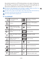
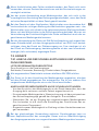
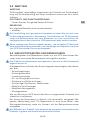
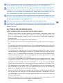
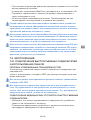
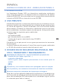
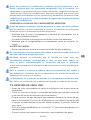
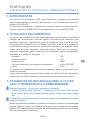
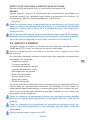
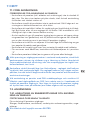
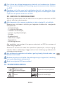
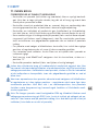
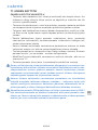
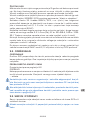
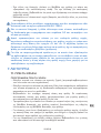
5. PRODUCT DESCRIPTION
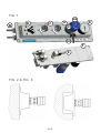
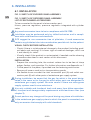
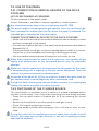
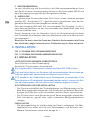
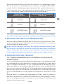
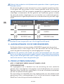
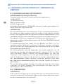
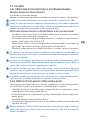
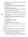
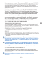
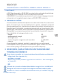
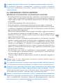
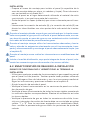
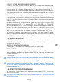
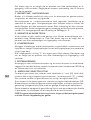
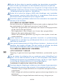
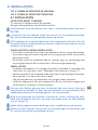
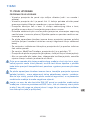
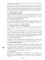
Fig. 1: Complex version of panel for exposed mounting
The inlet connection port (A) is intended for connection of a source of medi-
cal gas (e.g., pressure regulator, pressure regulator integrated with cylinder
valve, etc.) via a fl exible hose. The gas may come to the panel directly or
through the source cylinder switch (B).
The outlet from the panel is realized by the quick couplers (C) or by directly
connected MediFlow® selector outlet (G). The gas pressure indicator (D) is
an indicator of internal panel pressure. Gas from the medical gas pipeline
system is entering through the inlet connector (A).
It is possible to connect other parts of ambulance gas supply system via the
fl exible hoses connected to the outlet (E).
For the assembly, fastening accessories (F) may be provided. There are two
ways of the panel assembly – exposed or recessed assembly. Complete
kits including other accessories are available.

5/219
EN
A INLET CONNECTION PORT
It is intended for connection of medical gas source. The panel may be
equipped with one (one gas source) or two (two sources of gas, the panel is
equipped with a cylinder source switch) inlet connection ports.
B CYLINDER SOURCE SWITCH
By the cylinder source switch, it is possible to set the gas delivery to the
panel from source cylinder “1” or “2” or no delivery – position “0”.
It is an optional part of the panel. The cylinder source switch is also avail-
able as a separate part.
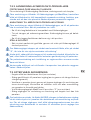
C TERMINAL UNITQUICK COUPLER
It is intended for connection of diff erent medical devices such as fl owme-
ters, ventilators, resuscitators, suction ejectors, etc.
It is designed according to the regional standards and is gas specifi c. The
quick coupler is automatically closed when a probe is disconnected and
self-opened during connection. The number of quick connectors diff ers fol-
lowing the panel version. Instructions for connection and disconnection of
the probes can be found in the Appendix nr. 2.
D GAS PRESSURE INDICATOR
It is indicating the internal pressure of the medical gas in the panel. The
used scale unit bars. It is an optional part of the panel, may not be available
at some versions of the panel.
E OUTLET CONNECTION PORT
It allows the connection of other parts of the ambulance gas supply sys-
tem via fl exible hoses. At versions with source cylinder switch, the outlet is
placed downstream the switch and when the switch is in position “0” there
is no gas supplied to the outlet connection port. This is an optional part of
the panel, may not be available at some versions of the panel.
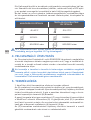
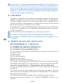
F FASTENING ACCESSORIES
Depending on the panel version and the construction of the ambulance
wall, there may be countersunk screws M5-16 and fi xing frame included
similar as shown in the picture.
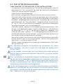
G MEDIFLOW® SELECTOR OUTLET
Requested gas fl ow can be adjusted by the handwheel (l/min) (G1). By
the handwheel, it is possible to regulate the gas fl ow – adjusting value
(“0”=closed). The adjusted value of the gas fl ow is visible in the reading
window (G2).
Gas is delivered to the user through the fl ow outlet user connection (G3).
The “fl ow outlet” user connection is usually equipped with a connection for
hose (a hose nipple) or a threaded connection (for humidifi er). This outlet
is for supplying a gas fl ow (l/min) at an atmospheric pressure directly to the
patient, e.g., through a cannula or a facemask.
Note also that products colour (especially handwheel) might not follow
any gas colour coding.

6/219
EN
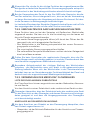
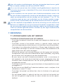
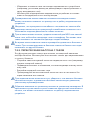
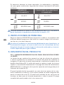
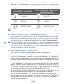
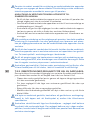
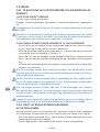
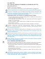
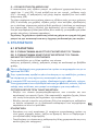
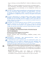
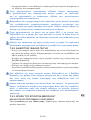
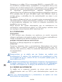
6. INSTALLATION
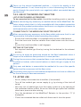
6.1. INSTALLATION
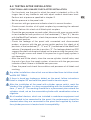
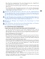
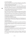
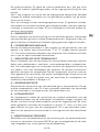
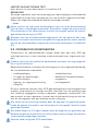
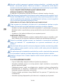
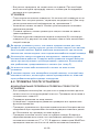
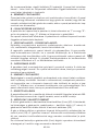
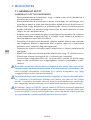
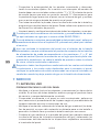
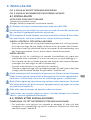
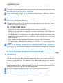
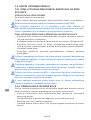
FIG. 2: SKETCH OF EXPOSED PANEL ASSEMBLY
FIG. 3: SKETCH OF RECESSED PANEL ASSEMBLY
LIST OF RECOGNISED ACCESSORIES
To be connected to the panel inlet connection port:
Hoses, pressure regulators, pressure regulators integrated with cylinder
valve
Any used accessories have to be in compliance with EN 1789.
Installation may be performed only by skilled technician and in compli-
ance with valid directives and standards.
GCE suggest to use accessories free of phtalates, if used accessories
contain any phtalates take into consideration possible risk for the patient.
VISUAL CHECK BEFORE INSTALLATION
• Check if there is visible external damage to the product (including prod-
uct labels and marking). If it shows signs of external damages, don´t use
it and identify its status.
• Visually check if the product is contaminated; if needed use the cleaning
procedure described in next section of this document.
INSTALLATION
• Prepare the mounting hole; the contact surface has to be free of sharp
edges, fl ashes, and impurities. For further information see Appendix no.1
• Fix the panel to the place, if provided use the fastening accessories.
• Remove all covers used just as transportation guards.
• Via fl exible hoses connect the inlet connection port (A) and outlet con-
nection port (E) with other parts of ambulance gas supply system.
During installation, be aware that the gas for which is the panel desig-
nated is the same as for the gas for which other parts are designated in
ambulance gas supply system. Be extra careful if there are more gases
supply systems used in one ambulance.
Use only suitable and functional tools and every time follow operation-
al, transport and storage safety requirements and cleanliness rules (see
chapter 3).
Do not perform any changes of the panel during any phase of installation.
In the ambulance gas supply system to which the panel is connected, use
only accessories that comply with valid standards.

7/219
EN
6.2. TESTING AFTER INSTALLATION
FUNCTIONAL AND LEAKAGE CHECK AFTER INSTALLATION
• For the check, use the gas for which the panel is intended, or Air or Ni-
trogen free of any lubricants and with equal medical cleanliness level.
Perform test at pressure specifi ed in chapter 2.
• Set the pressure to the panel inlet.
• At versions with gas pressure indicator check its correct function.
• Check correct function of all quick couplers by connecting the relevant
probe. Perform this check at all fi tted quick couplers.
• Check the gas presence on each outlet; Version with a gas source switch
to be checked at both positions of the handwheel (“1” and “2”). Version
with the MediFlow® selector - check the presence of the gas fl ow in every
handwheel position.
• Check the leakage of the panel with connected and disconnected
probes, at version with the gas source switch perform this check at all
positions of the handwheel (“1”, “0” and “2”), handwheel of the MediFlow®
selector (if equipped) must be in position “0”. For leakage detection GCE
suggest the pressure drop test based on the pressurizing the panel, clos-
ing of the gas source and check if the pressure in gas supply system is
not decreasing.
• After the end of the check, close the source cylinder shutoff valve, vent
the rest of gas from the supply system, at version with the gas pressure
indicator check if there is indicated zero pressure.
• Clean the panel and check the condition and presence of all labels and
marking.
Any other installation rules which are not described have to follow stand-
ard ENISO7396-1.
If there is found any leakage or defect on the panel, follow instructions
listed in chapter 9.3 and send the panel back to service repair.
After the installation of the panel with cylinder source switch, mark the
stands of the cylinders in a way corresponding with the handwheel posi-
tions „1“ and „2“. The marking should be in a permanent place where the
cylinders stand, not on the removable cylinder with combination valve or
regulator.
At all medical devices, which are included in ambulance equipment and
are intended to be connected to the panel, the performance should be
checked when they are connected to the panel and supplied by it,when
the cylinder pressure is low,to check its compatibility.

8/219
EN
7. OPERATION
7.1. BEFORE USE
CHECK BEFORE USE
• Visually check that the panel is not damaged (including labels and mark-
ing).
• Visually check the cleanliness of the panel; if needed clean panel follow-
ing cleaning procedure listed below of this document.
• Check suffi ciency of the cylinder pressure. In case of low cylinder pres-
sure, replace the cylinder or switch to another cylinder and replace the
empty cylinder with a full one.
• Turn on the medical gas to the ambulance panel inlet (e.g., by the open-
ing the of cylinder shutoff valve), during this operation follow the instruc-
tion for use of the cylinder shutoff valve.
• At version with cylinder source switch, check the correct position of the
handwheel (number indicated by the handwheel must correspond to the
number of the chosen cylinder).
• At version with the gas pressure indicator check correct panel pressure
indication.
• At version with the MediFlow® selector, check it is in position “0”.
• Check the leakage of the panel (e. g.by listening for the sound of gas
fl ow out).
• If there is any defect do not use the panel and mark that it is not allowed
to be used it and arrange for the service repair.
Before the fi rst use of any medical device which was not the original part
of the ambulance equipment, check its performance when connected to
the panel,especially in stage when the cylinder is going to be empty, to
check its compatibility.
At panels with cylinder source switch focus to the correct handwheel posi-
tion – have to be exactly in the selected position. If it is not, there may be
a risk of decreasing the fl ow capacity through the panel which can nega-
tively a ect connected devices performance.
You should remember that if you are using a panel with DIN QC for sup-
porting medical devices of an outlet fl ow 200l/min., the pressure on the
outlet side of the panel is about 1 bar lower than on the inlet side and than
indicated by the gas pressure indicator (if equipped).

9/219
EN
7.2. USE OF THE PANEL
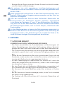
7.2.1. CONNECTION OF MEDICAL DEVICES TO THE QUICK
COUPLERS
LIST OF RECOGNISED ACCESSORIES
To be connected to the panel outlet:
Hoses, fl owmeters, ventilators, vacuum regulators, suction ejectors.
Any used accessories have to be in compliance with EN 1789.
The quick couplers are designed as gas specifi c, never try to connect de-
vices intended for another gas than for which the panel is intended. The
intended gas is indicated on the panel labels.
CONNECTION OF MEDICAL DEVICES TO THE QUICK COUPLERS
• Make sure that the outlet of the medical device to be connected is closed
and not connected to the patient.
• Connect the medical device to the panel by the procedure described in
Appendix Nr. 2.
• Check presence of the gas on the connected device outlet (e. g. by set-
ting a fl ow on the fl owmeter and listening of fl owing gas sound).
• Use connected medical device following its instruction for use.
When more panel outlets are used at the same time, the capacity of gas
supply and performance of the connected device may be negatively
a ected.
Make sure that the capacity of the equipment to be supplied by the panel
is corresponding with a capacity of the gas source equipment. Take into
account the pressure drop of the fl exible hoses.
At version of the panel for N2O or its mixtures, prevent the room from the
gas contamination. It could negatively a ect ambulance sta .
During use, keep checking the source cylinder pressure, if it is getting low
change the source or switch to another cylinder.
7.2.2. SWITCHING OF THE CYLINDER SOURCE
This functionality is available just at a version of a panel equipped with a
cylinder source switch. Use it only when switching from the empty cylinder.
• Open the not used source of medical gas (e. g. by opening the shutoff
valve)
• Switch the handwheel to position equal to new gas source
• Close the original medical gas source.
• Mark the empty cylinder and exchange it for a full one as soon as pos-
sible.
During the switch of the medical gas source, check that cylinder shut o
valve is fully open and cylinder pressure is not out of working pressure
specifi ed by producer.

10/219
EN
Focus on the correct handwheel position – it has to be exactly in the
selected position. If not, there may be a risk of decreasing the fl ow ca-
pacity through the panel which can negatively a ect connected devices
performance.
7.2.3. USE OF THE MEDIFLOW® SELECTOR
LIST OF RECOGNIZED ACCESSORIES
To be connected to the fl ow outlet: Humidifi er, breathing mask or cannula.
Before connecting any accessory or medical device to the MediFlow® Se-
lector, always check that it is fully compatible with the product connection
features & the product performances and there is no negative infl uence to
outlet parameters of the fl ow selector.
CONNECTION TO THE MEDIFLOW® SELECTOR OUTLET
When connecting any accessory to the fl ow outlet make sure that it is not
connected to the patient before operating the product.
• Ensure the hose/humidifi er is compatible with the fl ow outlet feature.
• Push the hose onto the fl ow selector fl ow outlet/screw onto the humidi-
fi e r .
• Ensure the hose/humidifi er is well engages.
SETTING OF THE FLOW
• Set required medical gas fl ow by turning the handwheel to the relevant
position.
Do not try to apply an excessive torque on the fl ow handwheel when it
stops on the maximum fl ow position or in zero position.
During the use ensure that connected hose is not mechanically damaged,
throttled or broken, which would reduce or break the gas supply to the
patient.
Only user and doctor is accountable for method of its use at the specifi c
patient and for assessment of the fl ow value.
Fluctuating inlet pressure and ambient temperature can have an infl uence
on the accuracy of fl ow measurement.
7.3. AFTER USE
• At fi rst, always disconnect the humidifi er (if connected).
• Turn off the medical gas source supply (e. g. by closing of the shut-off
valve)
• Vent any rest of medical gas from the supply system (e. g. by opening of
the connected device outlet). At version with the gas pressure indicator
check zero pressure after venting.
• Turn the handwheel of the MediFlow® Selector to the position “0” (if
equipped).
• Close the connected device outlet and disconnect it from the panel.

11/219
EN
If the humidifi ers are used, NEVER stop the fl ow on the humidifi er outlet.
There is a risk of the liquid entering to the gas supply system in time of
its venting. For stopping the fl ow from the humidifi er use the control of
device to which is humidifi er connected (e. g. fl owmeter handwheel).
8. CLEANING
Remove general contamination with a soft cloth damped in oil free oxygen
compatible soapy water & rinse with clean water.
Disinfection can be carried out with an alcohol-based solution (spray or
wipes).
If other cleaning solutions are used, check that they are not abrasive and
that they are compatible the product materials (including labels) and gas.
Do not use cleaning solutions containing ammonia!
Do not immerse in water or any liquid.
Do not expose to high temperature (such as autoclave).
9. PRODUCT LIFETIME, MAINTENANCE, SERVICE
9.1. PRODUCT LIFETIME
SERIAL NUMBER AND DATE OF PRODUCTION
Form of nine digit serial number stamped on the product is following:
YY MM XXXXX
YY: year of production
MM: month of production
XXXXX : sequence number
Example: serial number 090300521 shows the panel produced in March
2009, with sequence number 521.
LIFE TIME
Maximum life time of the product is 10 year from the date of manufacture.
At the end of the product’s life time, the product must be withdrawn from
the using. The owner shall put in place a relevant procedure to ensure the
product cannot be used again (marking, ).
The provider of the device shall prevent the reuse of the product and han-
dle the product in compliance with “Directive of European Parliament and
Council 2008/98/EC on waste“.
In accordance to Article 33 of REACH GCE, s.r.o. as responsible manufac-
turer shall inform all customers if materials containing 0.1% or more of sub-
stances included in the list of Substance of Very High Concern (SVHC).
The most commonly used brass alloys used for bodies and other brass
components contain 2-3% of lead (Pb), EC no. 231-468-6, CAS no. 7439-
92-1. The lead will not be released to the gas or surrounding environment
during normal use.

12/219
EN
After end of life the product shall be scrapped by an authorized metal re-
cycler to ensure effi cient material handling with minimal impact to environ-
ment and health.
To date we have no information that indicates that other materials contain-
ing SVHC of concentrations exceeding 0.1% are included in any GCE prod-
uct.
9.2. MAINTENANCE
MAINTENANCE
GCE suggest to perform yearly periodic inspection by the product owner.
The inspections include leakage and functional check of the panel.
LEAKAGE AND FUNCTIONAL CHECK
Perform the test according to chapter 6.2
REPAIR
Some repair activities concerning replacement of damaged or missing com-
ponents can be carried out by the owner of the product. The following com-
ponents can be replaced only:
• labels
Contact our customer service for appropriate component number. Users
cannot exchange the plate with the CE mark and serial number by them-
selves, without GCE´s consent.
If any leakage or defect is detected, stop using it,mark that it is not al-
lowed to be used and arrange for a service repair following the instruc-
tions listed in chapter 9.3
9.3. SERVICE AND REPAIRS
The service and repair shall be carried out by a GCE authorised person or
an authorised service technician only.
Never try to disassembly the product if it is connected to the pressure
source.
Repair activities cover the replacement of the following damaged or miss-
ing components:
• Quick couplers,
• O-rings and sealings,
• Gas pressure indicator,
• Inlet and Outlet connection,
• Hose assembly,
• Switch knob,
• Medi-Flow® selector,
• Suction ejector,
• Fixing frame.

13/219
EN
Any product sent back to a GCE authorised person for repair shall be prop-
erly packaged. The purpose of the delivery has to be clearly specifi ed (re-
pair, overall maintenance). For product to be repaired, a short description of
fault and any reference to a claim number would be helpful.
All labels on the equipment must be kept in a good, legible condition by
the owner and user during the entire product life time.
All seals and o-rings must be kept in dry, dark and clean environment by
the owner and the user during the entire product life time.
Use only original GCE components!
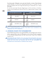
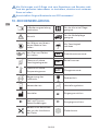
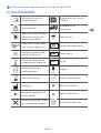
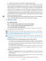
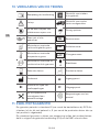
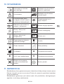
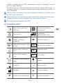
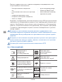
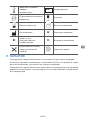
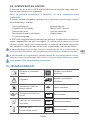
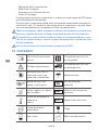
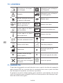
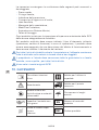
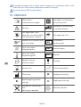
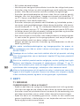
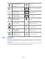
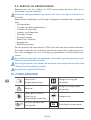
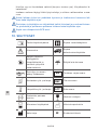
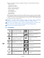
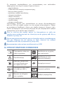
10. GLOSSARY
Consult operating
instruction
Suitable for Hospital
care use
Caution Suitable for Emergency
care use
Keep away from heat
sources and fl ammable
material
Keep dry
Keep away from oil and
grease SN Serial number
Upper and lower humid-
ity limit REF Reference number
Upper and lower tem-
perature limit LOT Batch number
Ambient pressure limit Fragile
Use by date Date of manufacture
Manufacturer A: Inlet connection port
B: Number and type of
quick couplers C: Outlet connection port

14/219
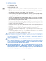
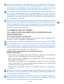
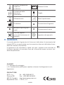
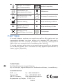
EN
Area to be cut out before
panel mounting Panel boundary
11. WARRANTY
The Standard Warranty period is two years from date of receipt by the GCE
Customer (or if this is not known 2 years from time of the product manufac-
ture shown on the product).
The standard warranty is only valid for products handled according to In-
struction for use (IFU) and general industry good practice and standards.
APPENDIX:
Nr 1: Mounting scheme
Nr 2: Quick coupling feature and connecting/disconnecting procedure
MANUFACTURER:
GCE, s.r.o. Tel : +420 569 661 111
Zizkova 381 Fax : +420 569 661 602
583 01 Chotebor http://www.gcegroup.com
Czech Republic © GCE, s.r.o.

15/219
DE
1. VORWORT
GCE Ambulance Panel sind Medizinprodukte, die als Klasse IIb gemäß der
Medizinprodukterichtlinie 93/42/EWG klassifi ziert sind.
Die Konformität mit den grundlegenden Anforderungen der Medizinpro-
dukterichtlinie 93/42/EWG ist aufgrund der Norm EN ISO 1789 gegeben.
2. VERWENDUNGSZWECK
Das Ambulancpanel ist eine zum Einbau in Rettungswagen vorgesehene
Anlage, die nach der Verbindung mit der Medizingasfl asche z.B. Druckmin-
derer oder Kombiventil als Steckdose für den Anschluss und die Versor-
gung der Medizinprodukte wie z.B. Flowmeter, Beatmung, Saugejektor usw.
dient. Zur Verfügung stehen die Versionen für folgende medizinische Gase:
• Sauerstoff O2
• medizinische Luft AIR
• Lachgas (Distickstoff monoxid) N2O
• Gasgemische z.B. O2+N2O
• Unterdruck VAC
Das Produkt ist nicht für die Verwendung mit Gasen von chirurgischen Ins-
trumenten vorgesehen.
Der Arbeitsdruck der Panel beträgt 4 bis 5 bar für medizinische Gase a ≤ 40
kPa (ausgedrückt im absoluten Druck) für Unterdruck.
3. SICHERHEITSANFORDERUNGEN AN BETRIEB,
TRANSPORT UND LAGERUNG
Das Produkt und die zugehörigen Geräte sind fernzuhalten¨von:
• Wärmequellen (Feuer, Zigaretten usw...),
• brennbaren Materialien,
• Ölen oder Fetten (erhöhte Vorsicht bei Gebrauch von Handcremen),
• Wasser,
• Staub.
Das Produkt und die zugehörigen Geräte müssen gegen das Umkippen
abgesichert werden.
Das Produkt und die zugehörigen Geräte nur in gut belüfteten Räumen
einsetzen.
Es sind die Normen zur Sauersto reinheit einzuhalten.
DEUTSCH
BEDIENUNGSANLEITUNG: AMBULANCE PANEL II

16/219
DE
Vor dem ersten Gebrauch muss sich das Produkt in seiner Originalverpa-
ckung befi nden. Im Falle der Außerbetriebsetzung für Transport und La-
gerung empfi ehlt GCE die Originalverpackung zu verwenden inkl. innerer
Füllstoff e .
Es sind die nationalen Gesetze, Regelungen und Vorschriften zu Unfallver-
hütung und Umweltschutz beim Einsatz von medizinischen Gasen zu be-
achten.
BETRIEBSBEDINGUNGEN LAGER UND
TRANSPORTBEDINGUNGEN
+5/+40°C -30/+70°C
10/100% 10/100%
600/1200 mbar 600/1200 mbar
Im Falle einer Lagerung bei einer Temperatur von +5°C dürfen die Panels
nicht in Betrieb genommen werden. Das Gerät muss mindestens eine
Temperatur von +5°C aufweisen.
4. ANWEISUNGEN FÜR MITARBEITER
Gemäß Medizingeräteverordnung 93/42/EWG, hat der Eigentümer des Pro-
dukts sicherzustellen, dass alle Mitarbeiter, die mit dem Produkt umgehen,
mit der Bedienungsanleitung und den technischen Daten des Produkts
vertraut sind.
Verwenden Sie das Produkt nicht, ohne dass Sie das Produkt und seinen
sicheren Betrieb kennen, wie in dieser Bedienungsanleitung angegeben.
Stellen Sie sicher, dass der Benutzer über die für das verwendete Gas
erforderlichen Informationen und Kenntnisse verfügt.

17/219
DE
5. PRODUKTBESCHREIBUNG
FIG. 1: REPRÄSENTATIVE VARIANTE DER PLATTE FÜR DIE
VORWANDMONTAGE
Die Quelle des medizinischen Gases (in der Regel Druckminderer oder
Kombiventil) wird mittels Schlauch an den Paneleingang (A) angeschlossen.
Das Gas strömt in das Panel direkt oder mittels eines Gasfl aschen-Wahl-
schalters hinein (B). Der Auslass des Panels erfolgt über Schnellkupplun-
gen (C) oder über den Ausgang des direkt angeschlossenen MediFlow®
(G). Der Arbeitsdruck wird mittels Druckanzeiger (D) angezeigt. Das Panel
ermöglicht, auch weitere Installationsteile in Reihe mittels Ausgang (E) an-
zuschließen. Optional kann ein Teil des Panels, das Verbindungsmaterial
(F) sein. Das Panel wird in zwei Montageversionen realisiert und zwar für
eingelassene Montage und Vorwandmontage. Verschiedene Varianten des
Panels können weitere Zubehörteile enthalten.
A EINGANGSANSCHLUSS
Der Eingangsanschluss dient für den Anschluss des medizinischen Gases
mittels Schlauch. Er kann doppelt für die Varianten mit Gasfl aschen-Wahl-
schalter oder einfach für die Versorgung aus nur einer Flasche sein.
B GASFLASCHENWAHLSCHALTER OPTIONAL
Mit dem Wahlschalter kann die Gasfl asche für die Gasversorgung einge-
stellt werden - Stellungen „1“ oder „2“, eventuell kann die Gasversorgung in
die Platte unterbrochen werden - „0“-Stellung.
C ENDDOSE SCHNELLKUPPLUNG
Sie dient für den Anschluss von Medizingeräten, wie MediMeter, Flowreg-
ler MediFlow Ultra, usw. Sie ist in der Variante gemäß den regionalen Nor-
men ausgeführt und erfüllt die Anforderungen an die Unverwechselbarkeit
der Gase. Die Schnellkupplung ist ohne angeschlossenes Medizingerät
geschlossen, durch den Gasanschluss wird sie automatisch geöff net und
durch die Abschaltung wird sie wieder automatisch geschlossen. Die Zahl
der installierten Schnellkupplungen hängt von der jeweiligen Variante der
Platte ab. Die Vorgehensweise für den Anschluss siehe Anlage Nr. 2.
D INNENDRUCKANZEIGER
Der Innendruckanzeiger ist ein Indikator für den Druck des medizinischen
Gases der sich in dem Panel befi ndet. Die verwendete Einheit ist in Bar an-
gegeben. Diese Variante des Panels ist ein optionales Zubehör und ist nicht
bei jedem Panel im Lieferumfang enthalten.
E AUSGANGSANSCHLUSS
Der Ausgangsanschluss ermöglicht weitere Komponenten der Rettungswa-
genverteilungen mittels Schlauch anzuschließen. Der Ausgangsanschluss
befi ndet sich hinter dem Gasfl aschen-Wahlschalter (falls vorhanden) und
wenn sich der Wahlschalter in der „0“ Stellung befi ndet, wird an den Aus-
gangsanschluss kein Gas zugeführt. Hierbei handelt es sich um ein optio-
nales Panelteil was nicht zu jedem Lieferumfang gehört.

18/219
DE
F MONTAGEMATERIAL
Je nach Ausführung und Konstruktion des Rettungswagenau aues kann
das Panel mit einer entsprechenden Anzahl an Senkschrauben M5-16 und
dem Montagerahmen gemäß dem Bild geliefert werden.
G MEDIFLOW®
Der gewünschte Gasdurchfl usswert (l/min) kann mittels Handrad geregelt
werden (G1) – Einstellwert (“0” = geschlossen).Im Lesefenster kann der ein-
gestellte Gasdurchfl usswert abgelesen werden (G2).
Über den Ausgang (G3) fl ießt Gas zum Anwender. Der Ausgang, ist mit ei-
nem Gewinde versehen, an das man entweder einen Befeuchter oder eine
Tülle anschließen kann.
Dieser Ausgang ist für die Gaszufuhr (l/min) mit Atmosphärendruck direkt
zum Patienten, zum Beispiel über eine Nasenbrille oder eine Gesichtsmas-
ke vorgesehen.
Beachten Sie auch, dass die Farbe des Produkts (insbesondere die Farbe
des Handrads) möglicherweise keiner Farbkodierung für Gase entspricht.
6. INSTALLATION
FIG. 2: SCHEMA DER VORWANDMONTAGE
FIG. 3: SCHEMA DER EINGELASSENEN MONTAGE
6.1. INSTALLATION
LISTE DER ZUGELASSENEN ZUBEHÖRTEILE
Zum Anschluss an den Paneleingang:
Schläuche, Druckminderer, Kombiventile.
Alle angewandten Zubehörteile müssen die Norm EN 1789 erfüllen.
Die Installation dürfen nur Personen mit entsprechenden Kenntnissen ge-
mäß den geltenden Vorschriften und Normen durchführen.
GCE empfi ehlt, die Zubehörteile ohne Phtalatgehalt zu verwenden. Falls
Zubehörteile mit Phtalatgehalt verwendet werden sollen, müssen die Risi-
ken beurteilt werden, die sich daraus für Patienten ergeben können.
SICHTPRÜFUNG VOR DER INSTALLATION
• Das Panel einschließlich der Produktetiketten und Markierungen auf äu-
ßere Beschädigungen überprüfen. Bei Anzeichen auf äußerer Beschädi-
gungen die Platte nicht mehr verwenden und den Status kennzeichnen.
• Das Produkt durch eine Sichtprüfung auf Verunreinigungen überprüfen.
Falls erforderlich, gemäß dem unten erläuterten Reinigungsverfahren
reinigen.
INSTALLATION
• Die Montageöff nung für die Montage des Panels vorbereiten. Die Mon-
tagefl äche muss eben und frei von Schutzkappen und Schmutz sein .
Weitere Informationen siehe auch Anlage Nr. 1

19/219
DE
• Das Panel am vorgesehenen Ort unter Verwendung des mitgelieferten
Montagematerials, montieren , (falls vorhanden).
• Von dem Panel alle Abdeckungen abnehmen, die für den Transport ge-
dacht sind .
• Die Verbindung des Eingangsanschlusses (A) und des Ausgangsan-
schlusses (E) mit Hilfe fl exibler Schläuche mit sonstigen Teilen der Ret-
tungswagenverteilungen herstellen.
Während der Montage beachten, dass das von der angeschlossenen
Quelle zugeführte Gas, dem Gas entspricht, für dass das Panel bestimmt
ist. Vorsicht walten lassen falls die Verteilungssysteme vom Rettungswa-
gen für mehr als eine Gasart bestimmt ist.
Für die Montage immer passende und funktionsfähige Werkzeuge ver-
wenden und die Sicherheitsanforderungen für Betrieb, Verkehr und Lage-
rung beachten. Das Panel sauber halten. (siehe Kapitel 3).
Während der Montage keine Eingri e oder Anpassungen am Panel
vornehmen.
In der Verteilung, in der das Panel einen Bestandteil bildet, nur Zubehör-
teile montieren, die die geltenden Normen erfüllen.
6.2. PRÜFUNG NACH MONTAGE
FUNKTIONS UND DICHTHEITSPRÜFUNG NACH DER MONTAGE
• Für den Test benutzen Sie das für das Panel vorgesehene Gas, oder Air
oder Nitrogen, frei von Schmierstoff en und mit gleichem medizinischem
Reinheitsgrad. Führen Sie den Test wie in Kapitel 2 beschrieben durch.
• Den Paneleingang mit Druck belasten.
• Geben Sie Druck auf den Eingang.
• Bei Versionen mit Gasdruckindikator prüfen Sie seine korrekte Funktion.
• Überprüfen Sie die korrekte Funktion aller Schnellkupplungen durch An-
schließen des entsprechenden Steckers. Führen Sie diese Prüfung bei
allen eingebauten Schnellkupplungen durch.
• Prüfen Sie an jedem Ausgang ob Gas fl ießt; bei Versionen mit Gasquel-
lenumschalter muss bei beiden Positionen des Handrads geprüft werden
(“1” und “2”). Bei Versionen mit einem MediFlow® - prüfen Sie den Gas-
fl uss in jeder Einstellung des Handrads.
• Prüfen Sie die Dichtheit des Panels mit und ohne angeschlossenen Ste-
ckern. Bei Versionen mit Gasquellenumschalter muss bei beiden Posi-
tionen des Handrads geprüft werden (“1” und “2”), das Handrad des Me-
difl ow (falls angeschlossen) muss auf Position 0 stehen. Zur Lecksuche
empfi ehlt GCE eine Druckabfallprüfung indem Sie das Panel unter Druck
setzen, die Gasquelle schließen und prüfen, ob sich der Druck in der Gas-
versorgungsanlage nicht verringert.
• Nach Beendigung des Tests, schließen Sie das Absperrventil der Gas-
fl asche und entlüften das Versorgungssystem. Bei Versionen mit Druck-
anzeige, prüfen Sie, dass diese „0“ anzeigt.

20/219
DE
• Reinigen Sie das Panel und prüfen Sie den Zustand und das Vorhanden-
sein aller Label und Markierungen
Alle weiteren, hier nicht angegebenen Installationsbedingungen und
Prüfverfahren nach der Installation, richten sich nach der geltenden Norm
ENISO7396-1.
Wenn Leckage oder andere Fehler an dem Panel entdeckt werden, die im
Kapitel 9.3 beschriebene Vorgehensweise anwenden und das Panel zur
Reparatur zurückgeben.
Nach der Installation der Panel mit dem Gasfl aschen -Wahlschalter die
Anschlussstellen der Gasfl aschen deutlich markieren, entsprechend
in der Weise der Positionen „1“ und „2“ des Wahlschalters. Die Markie-
rung muss sich an der Stelle befi nden, die einen unteilbaren Bestandteil
des Rettungswagens bildet, nicht an einem Absperr-, Kombiventil oder
Druckminderer.
An allen Medizingeräten, mit denen der Rettungswagen ausgestattet ist,
und die für den Anschluss an die Platte vorgesehen sind, die Prüfung der
Ausgangsparameter in der Verbindung mit der installierten Platte im Zu-
stand mit einem niedrigen Flaschengasdruck durchführen.
7. BETRIEB
7.1. VOR DEM EINSATZ
VORBEREITUNG FÜR DIE VERWENDUNG DER PANELS
• Das Panel (einschließlich der Produktetiketten und Markierungen) auf
äußere Beschädigungen überprüfen. Bei Anzeichen äußerer Beschädi-
gungen das Panel nicht mehr verwenden und den Status kennzeichnen.
• Das Produkt mittels Sichtprüfung auf Verunreinigungen überprüfen; falls
erforderlich, gemäß dem unten erläuterten Reinigungsverfahren reini-
gen.
• Prüfen Sie den Flaschendruck. Bei nicht ausreichendem Druck sollte die
Gasfl asche ersetzt werden oder schalten Sie auf eine volle Flasche und
tauschen die Gasfl asche mit ungenügendem Inhalt aus.
• An dem Paneleingang das medizinische Gas zuführen (z.B. durch das
Öff nen des Absperrventils der Gasfl asche ), dabei ist den Anweisungen
des Herstellers Folge zu leisten.
• Bei dem Panels die mit Gasfl aschen -Wahlschaltern ausgestattet sind,
falls notwending die richtige Position des Wahlschalters kontrollieren.
• Bei Versionen mit einem MediFlow, prüfen Sie, ob dieser in Position
„0“ist.
• Bei der Variante mit Innendruckanzeige prüfen, ob der Druck innerhalb
der Panels richtig angezeigt wird.
• Die Dichtheit der Panel kontrollieren (z.B. akustische Überprüfung auf
Zischlaute).
La pagina si sta caricando...
La pagina si sta caricando...
La pagina si sta caricando...
La pagina si sta caricando...
La pagina si sta caricando...
La pagina si sta caricando...
La pagina si sta caricando...
La pagina si sta caricando...
La pagina si sta caricando...
La pagina si sta caricando...
La pagina si sta caricando...
La pagina si sta caricando...
La pagina si sta caricando...
La pagina si sta caricando...
La pagina si sta caricando...
La pagina si sta caricando...
La pagina si sta caricando...
La pagina si sta caricando...
La pagina si sta caricando...
La pagina si sta caricando...
La pagina si sta caricando...
La pagina si sta caricando...
La pagina si sta caricando...
La pagina si sta caricando...
La pagina si sta caricando...
La pagina si sta caricando...
La pagina si sta caricando...
La pagina si sta caricando...
La pagina si sta caricando...
La pagina si sta caricando...
La pagina si sta caricando...
La pagina si sta caricando...
La pagina si sta caricando...
La pagina si sta caricando...
La pagina si sta caricando...
La pagina si sta caricando...
La pagina si sta caricando...
La pagina si sta caricando...
La pagina si sta caricando...
La pagina si sta caricando...
La pagina si sta caricando...
La pagina si sta caricando...
La pagina si sta caricando...
La pagina si sta caricando...
La pagina si sta caricando...
La pagina si sta caricando...
La pagina si sta caricando...
La pagina si sta caricando...
La pagina si sta caricando...
La pagina si sta caricando...
La pagina si sta caricando...
La pagina si sta caricando...
La pagina si sta caricando...
La pagina si sta caricando...
La pagina si sta caricando...
La pagina si sta caricando...
La pagina si sta caricando...
La pagina si sta caricando...
La pagina si sta caricando...
La pagina si sta caricando...
La pagina si sta caricando...
La pagina si sta caricando...
La pagina si sta caricando...
La pagina si sta caricando...
La pagina si sta caricando...
La pagina si sta caricando...
La pagina si sta caricando...
La pagina si sta caricando...
La pagina si sta caricando...
La pagina si sta caricando...
La pagina si sta caricando...
La pagina si sta caricando...
La pagina si sta caricando...
La pagina si sta caricando...
La pagina si sta caricando...
La pagina si sta caricando...
La pagina si sta caricando...
La pagina si sta caricando...
La pagina si sta caricando...
La pagina si sta caricando...
La pagina si sta caricando...
La pagina si sta caricando...
La pagina si sta caricando...
La pagina si sta caricando...
La pagina si sta caricando...
La pagina si sta caricando...
La pagina si sta caricando...
La pagina si sta caricando...
La pagina si sta caricando...
La pagina si sta caricando...
La pagina si sta caricando...
La pagina si sta caricando...
La pagina si sta caricando...
La pagina si sta caricando...
La pagina si sta caricando...
La pagina si sta caricando...
La pagina si sta caricando...
La pagina si sta caricando...
La pagina si sta caricando...
La pagina si sta caricando...
La pagina si sta caricando...
La pagina si sta caricando...
La pagina si sta caricando...
La pagina si sta caricando...
La pagina si sta caricando...
La pagina si sta caricando...
La pagina si sta caricando...
La pagina si sta caricando...
La pagina si sta caricando...
La pagina si sta caricando...
La pagina si sta caricando...
La pagina si sta caricando...
La pagina si sta caricando...
La pagina si sta caricando...
La pagina si sta caricando...
La pagina si sta caricando...
La pagina si sta caricando...
La pagina si sta caricando...
La pagina si sta caricando...
La pagina si sta caricando...
La pagina si sta caricando...
La pagina si sta caricando...
La pagina si sta caricando...
La pagina si sta caricando...
La pagina si sta caricando...
La pagina si sta caricando...
La pagina si sta caricando...
La pagina si sta caricando...
La pagina si sta caricando...
La pagina si sta caricando...
La pagina si sta caricando...
La pagina si sta caricando...
La pagina si sta caricando...
La pagina si sta caricando...
La pagina si sta caricando...
La pagina si sta caricando...
La pagina si sta caricando...
La pagina si sta caricando...
La pagina si sta caricando...
La pagina si sta caricando...
La pagina si sta caricando...
La pagina si sta caricando...
La pagina si sta caricando...
La pagina si sta caricando...
La pagina si sta caricando...
La pagina si sta caricando...
La pagina si sta caricando...
La pagina si sta caricando...
La pagina si sta caricando...
La pagina si sta caricando...
La pagina si sta caricando...
La pagina si sta caricando...
La pagina si sta caricando...
La pagina si sta caricando...
La pagina si sta caricando...
La pagina si sta caricando...
La pagina si sta caricando...
La pagina si sta caricando...
La pagina si sta caricando...
La pagina si sta caricando...
La pagina si sta caricando...
La pagina si sta caricando...
La pagina si sta caricando...
La pagina si sta caricando...
La pagina si sta caricando...
La pagina si sta caricando...
La pagina si sta caricando...
La pagina si sta caricando...
La pagina si sta caricando...
La pagina si sta caricando...
La pagina si sta caricando...
La pagina si sta caricando...
La pagina si sta caricando...
La pagina si sta caricando...
La pagina si sta caricando...
La pagina si sta caricando...
La pagina si sta caricando...
La pagina si sta caricando...
La pagina si sta caricando...
La pagina si sta caricando...
La pagina si sta caricando...
La pagina si sta caricando...
La pagina si sta caricando...
La pagina si sta caricando...
La pagina si sta caricando...
La pagina si sta caricando...
La pagina si sta caricando...
La pagina si sta caricando...
La pagina si sta caricando...
La pagina si sta caricando...
La pagina si sta caricando...
La pagina si sta caricando...
La pagina si sta caricando...
La pagina si sta caricando...
La pagina si sta caricando...
La pagina si sta caricando...
La pagina si sta caricando...
La pagina si sta caricando...
La pagina si sta caricando...
La pagina si sta caricando...
-
 1
1
-
 2
2
-
 3
3
-
 4
4
-
 5
5
-
 6
6
-
 7
7
-
 8
8
-
 9
9
-
 10
10
-
 11
11
-
 12
12
-
 13
13
-
 14
14
-
 15
15
-
 16
16
-
 17
17
-
 18
18
-
 19
19
-
 20
20
-
 21
21
-
 22
22
-
 23
23
-
 24
24
-
 25
25
-
 26
26
-
 27
27
-
 28
28
-
 29
29
-
 30
30
-
 31
31
-
 32
32
-
 33
33
-
 34
34
-
 35
35
-
 36
36
-
 37
37
-
 38
38
-
 39
39
-
 40
40
-
 41
41
-
 42
42
-
 43
43
-
 44
44
-
 45
45
-
 46
46
-
 47
47
-
 48
48
-
 49
49
-
 50
50
-
 51
51
-
 52
52
-
 53
53
-
 54
54
-
 55
55
-
 56
56
-
 57
57
-
 58
58
-
 59
59
-
 60
60
-
 61
61
-
 62
62
-
 63
63
-
 64
64
-
 65
65
-
 66
66
-
 67
67
-
 68
68
-
 69
69
-
 70
70
-
 71
71
-
 72
72
-
 73
73
-
 74
74
-
 75
75
-
 76
76
-
 77
77
-
 78
78
-
 79
79
-
 80
80
-
 81
81
-
 82
82
-
 83
83
-
 84
84
-
 85
85
-
 86
86
-
 87
87
-
 88
88
-
 89
89
-
 90
90
-
 91
91
-
 92
92
-
 93
93
-
 94
94
-
 95
95
-
 96
96
-
 97
97
-
 98
98
-
 99
99
-
 100
100
-
 101
101
-
 102
102
-
 103
103
-
 104
104
-
 105
105
-
 106
106
-
 107
107
-
 108
108
-
 109
109
-
 110
110
-
 111
111
-
 112
112
-
 113
113
-
 114
114
-
 115
115
-
 116
116
-
 117
117
-
 118
118
-
 119
119
-
 120
120
-
 121
121
-
 122
122
-
 123
123
-
 124
124
-
 125
125
-
 126
126
-
 127
127
-
 128
128
-
 129
129
-
 130
130
-
 131
131
-
 132
132
-
 133
133
-
 134
134
-
 135
135
-
 136
136
-
 137
137
-
 138
138
-
 139
139
-
 140
140
-
 141
141
-
 142
142
-
 143
143
-
 144
144
-
 145
145
-
 146
146
-
 147
147
-
 148
148
-
 149
149
-
 150
150
-
 151
151
-
 152
152
-
 153
153
-
 154
154
-
 155
155
-
 156
156
-
 157
157
-
 158
158
-
 159
159
-
 160
160
-
 161
161
-
 162
162
-
 163
163
-
 164
164
-
 165
165
-
 166
166
-
 167
167
-
 168
168
-
 169
169
-
 170
170
-
 171
171
-
 172
172
-
 173
173
-
 174
174
-
 175
175
-
 176
176
-
 177
177
-
 178
178
-
 179
179
-
 180
180
-
 181
181
-
 182
182
-
 183
183
-
 184
184
-
 185
185
-
 186
186
-
 187
187
-
 188
188
-
 189
189
-
 190
190
-
 191
191
-
 192
192
-
 193
193
-
 194
194
-
 195
195
-
 196
196
-
 197
197
-
 198
198
-
 199
199
-
 200
200
-
 201
201
-
 202
202
-
 203
203
-
 204
204
-
 205
205
-
 206
206
-
 207
207
-
 208
208
-
 209
209
-
 210
210
-
 211
211
-
 212
212
-
 213
213
-
 214
214
-
 215
215
-
 216
216
-
 217
217
-
 218
218
-
 219
219
-
 220
220


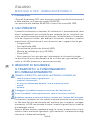
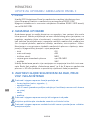
GCE AMBULANCE PANEL II Istruzioni per l'uso
- Tipo
- Istruzioni per l'uso
in altre lingue
Documenti correlati
-
GCE MEDIFLOWTEC, MEDIFLOW II, MEDIFLOW + Istruzioni per l'uso
-
-
-
-
-
-
-
-
-