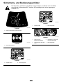
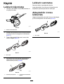
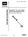
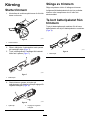
Toro PowerPlex 33cm 40V MAX String Trimmer Manuale utente
- Categoria
- Tagliaerba
- Tipo
- Manuale utente

FormNo.3418-116RevB
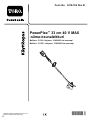
PowerPlex™33cm40VMAXStringTrimmer
51130,51130T
StrunovývyžínačPowerPlex™,33cm,40V
MAX.
51130,51130T
Faden-FreischneiderPowerPlex™,33cm,
max.40Volt
51130,51130T
CortasetosPowerPlex™40VMAXde33cm
51130,51130T
PowerPlex™33cm40VMAX-siimaleikkuri
51130,51130T
DébroussailleuseàlPowerPlex™33cm40V
MAX
51130,51130T
DecespugliatorePowerPlex™33cm40VMAX
51130,51130T
PowerPlex™33cm40VMAXdraadtrimmer
51130,51130T
PowerPlex™33cm40VMAX-gresstrimmer
51130,51130T
www.T oro.com.
*3418-116*B

FormNo.3418-116RevB
KosażyłkowaPowerPlex™33cm40VMAX
51130,51130T
PowerPlex™33cm40VMAXtrådtrimmer
51130,51130T
www.T oro.com.
*3418-116*B


ThisproductcomplieswithallrelevantEuropean
directives.Fordetails,pleaseseetheseparate
productspecicDeclarationofConformity(DOC)
sheet.
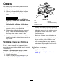
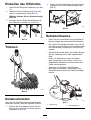
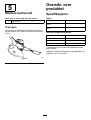
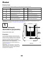
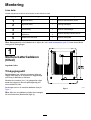
Introduction
Thistrimmerisintendedtobeusedbyresidential
homeownerstotrimgrassasneeded.Itisdesigned
touseonlybatterypackmodels88525(providedwith
model51130)or88526.
Readthisinformationcarefullytolearnhowtooperate
andmaintainyourproductproperlyandtoavoid
injuryandproductdamage.Youareresponsiblefor
operatingtheproductproperlyandsafely.
YoumaycontactT orodirectlyatwww.Toro.comfor
productandaccessoryinformation,helpndinga
dealer,completewarrantydetails,ortoregisteryour
product.
Model51130Tdoesnotincludeabatteryora
charger.
Safety
WARNING:Whenusingelectricgardeningappliances,
alwaysfollowbasicsafetyprecautionstoreduce
theriskofre,electricshock,andpersonalinjury,
includingthefollowing:
WARNING
Failuretofollowallwarningsandinstructions
mayresultinelectricshock,reand/or
seriouspersonalinjury.
Readallsafetywarningsandallinstructions.
Saveallwarningsandinstructionsforfuture
reference.
Theterm“powertool”inallthewarningsrefers
toyourmains-operated(corded)powertoolor
battery-operated(cordless)powertool.
1.Workareasafety
A.Keeptheworkareacleanandwelllit.
Clutteredordarkareasinviteaccidents.
B.Donotoperatepowertoolsinexplosive
atmospheres,suchasinthepresence
ofammableliquids,gasses,ordust.
Powertoolscreatesparks,whichmayignite
thedustorfumes.
C.Keepchildrenandbystandersaway
whileoperatingapowertool.Distractions
cancauseyoutolosecontrol.
D.Avoiddangerousenvironments.Donot
useappliancesindamporwetlocations.
2.Personalsafety
A.Stayalert;watchwhatyouaredoing
andusecommonsensewhenoperating
apowertool.Donotuseapowertool
whileyouaretiredorundertheinuence
ofdrugs,alcohol,ormedication.A
momentofinattentionwhileoperatingpower
toolsmayresultinseriouspersonalinjury.
B.Usepersonalprotectiveequipment.
Alwaysweareyeprotection.Protective
equipmentsuchasadustmask,non-skid
safetyshoes,ahardhat,orhearing
protectionusedforappropriateconditions
willreducepersonalinjuries.
C.Preventunintentionalstarting.Ensure
theswitchisintheOFFpositionbefore
connectingtopowersourceand/or
batterypackandpickinguporcarrying
thetool.Carryingpowertoolswithyour
ngerontheswitchorenergizingpower
toolsthathavetheswitchoninvites
accidents.
©2018—TheToro®Company
8111LyndaleAvenueSouth
Bloomington,MN55420
2
Contactusatwww.Toro.com.
PrintedinChina
AllRightsReserved

D.Donotoverreach.Keepproper
footingandbalanceatalltimes.This
enablesbettercontrolofthepowertoolin
unexpectedsituations.
E.Dressproperly.Donotwearloose
clothingorjewelry.Keepyourhair,
clothing,andglovesawayfrommoving
parts.Looseclothes,jewelry,orlonghair
canbecaughtinmovingparts.
F.Keepyourhandsandfeetawayfromthe
cuttingarea.
3.Powertooluseandcare
A.Donotforcethepowertool.Usethe
correctpowertoolforyourapplication.
Thecorrectpowertoolwilldothejob
betterandsaferattherateforwhichitwas
designed.
B.Donotusethepowertooliftheswitch
doesnotturnitonandoff.Anypowertool
thatcannotbecontrolledwiththeswitchis
dangerousandmustberepaired.
C.Removethebatterypackfromthepower
toolbeforemakinganyadjustments,
changingaccessories,orstoringpower
tools.Suchpreventivesafetymeasures
reducetheriskofstartingthepowertool
accidentally.
D.Storeidlepowertoolsoutofthereach
ofchildrenanddonotallowpersons
unfamiliarwiththepowertoolorthese
instructionstooperatethepowertool.
Powertoolsaredangerousinthehandsof
untrainedusers.
E.Storeidleappliancesindoors.Whennot
inuse,appliancesshouldbestoredindoors
inadryandhighorlocked-upplace,outof
thereachofchildren.
F.Maintainpowertools.Checkfor
misalignmentorbindingofmoving
parts,breakageofparts,andanyother
conditionthatmayaffecttheoperation
ofpowertools.Ifdamaged,havethe
powertoolrepairedbeforeuse.Many
accidentsarecausedbypoorlymaintained
powertools.
G.Maintainappliancewithcare.Keep
cuttingedgesharpandcleanforbest
performanceandtoreducetheriskof
injury.Followinstructionsforlubricatingand
changingaccessories.Keephandlesdry,
clean,andfreefromoilandgrease.
H.Keepcuttingtoolssharpandclean.
Properlymaintainedcuttingtoolswithsharp
cuttingedgesarelesslikelytobindandare
easiertocontrol.
I.Usethepowertoolinaccordancewith
theseinstructionsandinthemanner
intendedfortheparticulartypeofpower
tool,takingintoaccounttheworking
conditionsandtheworktobeperformed.
Usingthepowertoolforoperationsdifferent
fromthoseintendedcouldresultina
hazardoussituation.
J.Keepguardsinplaceandinworking
order.
K.Checkfordamagedparts.Beforeusing
theappliance,carefullycheckaguardor
otherpartthatisdamagedtodetermine
thatitwilloperateproperlyandperform
itsintendedfunction.Checkforalignment
ofmovingparts,bindingofmovingparts,
breakageofparts,mounting,andanyother
conditionthatmayaffectitsoperation.A
guardorotherpartthatisdamagedshould
beproperlyrepairedorreplacedbyan
authorizedservicecenterunlessindicated
elsewhereinthismanual.
4.Service
Haveyourpowertoolservicedbya
qualiedrepairpersonusingonlyidentical
replacementparts.Thiswillensurethatthe
safetyofthepowertoolismaintained.
5.BatterySafety
A.Donotchargeapplianceinrainorinwet
locations.
B.Donotusebattery-operatedappliancein
therain.
C.Useonlythefollowingtypeandsize
battery(ies):TorobatteryModel88525or
88526.
D.Removeordisconnectthebatterybefore
servicing,cleaning,orremovingmaterial
fromthegardeningappliance.
E.Donotdisposeofthebattery(ies)ina
re.Thecellmayexplode.Checkwith
localcodesforpossiblespecialdisposal
instructions.
F.Donotopenormutilatethebattery(ies).
Releasedelectrolyteiscorrosiveandmay
causedamagetotheeyesorskin.Itmay
betoxicifswallowed.
G.Exercisecareinhandlingbatteriesinorder
nottoshortthebatterywithconducting
materialssuchasrings,bracelets,andkeys.
Thebatteryorconductormayoverheatand
causeburns.
SAVETHESEINSTRUCTIONS
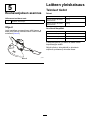
3

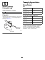
SoundPressure
Thisunithasasoundpressurelevelattheoperator’s
earof83.1dBA,withanUncertaintyValue(K)of3
dBA.
Thesoundpressurelevelwasdeterminedaccording
totheproceduresoutlinedinENISO11201.
SoundPower
Thisunithasaguaranteedsoundpowerlevelof96
dBA,whichincludesanUncertaintyValue(K)of1.02
dBA.
Thesoundpowerlevelwasdeterminedaccordingto
theproceduresoutlinedinENISO11094.
Hand/ArmVibration
Measuredvibrationlevelforrighthand=2.19m/s
2
Measuredvibrationlevelforlefthand=2.06m/s
2
UncertaintyValue(K)=1.5m/s
2
Themeasuredvaluesweredeterminedaccordingto
theproceduresoutlinedinENISO20643.
Important:Thevibrationemissionduringactual
useofthepowertoolcandifferfromthedeclared
totalvaluedependingonthewaythetoolis
used.Theoperatorshouldtakesafetymeasures
basedonanestimationofexposureintheactual
conditionsofuse.
4

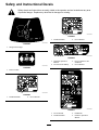
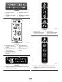
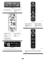
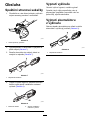
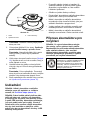
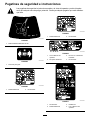
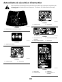
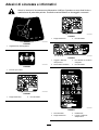
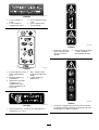
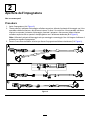
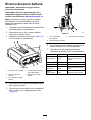
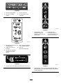
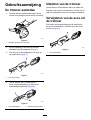
SafetyandInstructionalDecals
Safetydecalsandinstructionsareeasilyvisibletotheoperatorandarelocatednearanyarea
ofpotentialdanger.Replaceanydecalthatisdamagedormissing.
decal136-2482
136-2482
1.Stringtrimmeredger
decal136-2484
136-2484
1.Presstorotate.
decal136-2489
136-2489
1.Doubleinsulated2.Donotdiscard.
decal136-2490
136-2490
1.Doubleinsulated2.Donotdiscard.
decal136-2499
136-2499
1.ReadtheOperator’s
Manual.
3.Donotoperateinwet
conditions.
2.Donotburnthebattery.4.Donotdiscard.
decal136-2501
136-2501
1.Donotdiscard.3.Residential
2.Doubleinsulated
4.ReadtheOperator’s
Manual.
5

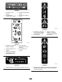
decal136-2504
136-2504
1.Thebatterypackis
charging.
3.Thebatterypackistoo
warm.
2.Thebatterypackisfully
charged.
4.Thebatterypackneedsto
bereplaced.
decal136-2534
136-2534
1.Thebatterydoesnot
comeoutoftheboxfully
charged.
4.Stop—followthese
instructionsbeforerst
use.
2.Placethebatteryinthe
batterycharger.
5.ReadtheOperator’s
Manual.
3.Waituntilthebatteryis
fullychargedbeforethe
rstuse.
decal136-2539
136–2539
1.Chargethebatterywherethetemperatureisbetween0°C
and40°C(32°Fand104°F).
decal136-2535
136-2535
1.Warning—keep
bystandersawayfromthe
machineinalldirections.
2.Thrownobject
hazard—keepbystanders
awayfromthemachine.
decal136-2537
136-2537
1.Warning—readtheOperator’sManual;wearhearing
protection;weareyeprotection;donotoperateinwet
conditions.
6

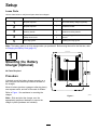
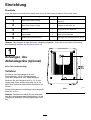
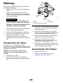
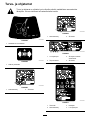
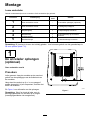
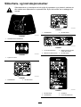
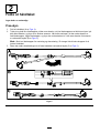
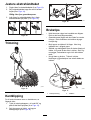
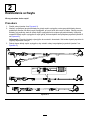
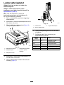
Setup
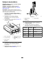
LooseParts
Usethechartbelowtoverifythatallpartshavebeenshipped.
ProcedureDescription
Qty.
Use
1
Nopartsrequired
–
Mountthebatterycharger(optional).
2
Nopartsrequired
–
Unfoldthehandle.
3
Auxiliaryhandle1Installtheauxiliaryhandle.
Guard
1
4
Phillipsheadscrew3
Mountingtheguardtothebaseofthe
trimmer.
5
Wireedgeguard1Installingtheedgeguard
Note:Thebatterypackisnotfullychargedwhenyoupurchaseit.Beforeusingthetoolforthersttime,refer
toChargingtheBatteryPack(page12).
1
MountingtheBattery
Charger(Optional)
NoPartsRequired
Procedure
Ifdesired,mountthebatterychargersecurelyona
wallusingthewall-mountkeyholesonthebackof
thecharger.
Mountitindoors(suchasagarageorotherdryplace),
nearapoweroutlet,andoutofthereachofchildren.
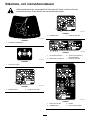
RefertoFigure1forassistanceinmountingthe
charger.
Note:Slideandtwistthechargeroverthe
appropriatelypositionedhardwaretosecurethe
chargerinplace(hardwarenotincluded).
g194202
Figure1
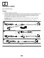
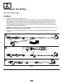
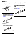
7

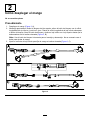
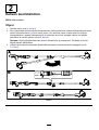
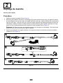
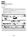
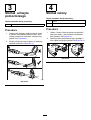
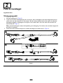
2
UnfoldingtheHandle
NoPartsRequired
Procedure
1.Unfoldthehandle(AofFigure2).
2.Pressandholdthelockingbuttonontheuppershaft,alignthelockingbuttonwiththeslottedholeonthe
lowershaft,andslidethe2shaftstogether.Oncetheslottedholeonthelowershaftispastthelocking
button,releasethelockingbutton,andslidethelowershaftintotheuppershaftuntilthetrimmeris
atthedesiredheight(BofFigure2).
Note:Usethelockingbuttononlyforassemblyanddisassembly.Youdonotneedtousethebuttonto
adjustthehandle.
3.Tightenthelowershaftconnectortosecurethehandleatthedesiredheight(CofFigure2).
g195351
Figure2
8

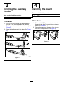
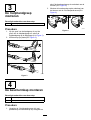
3
InstallingtheAuxiliary
Handle
Partsneededforthisprocedure:
1Auxiliaryhandle
Procedure
1.Lineupthegroovealongthehandlewiththe
grooveontheauxiliaryhandleandslidethe
auxiliaryhandletowardthetrimmerhandle(Aof
Figure3).
2.Snapthehandlesecurelyintoplace(BofFigure
3).
g195362
Figure3
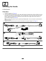
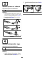
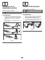
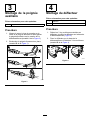
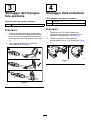
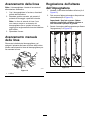
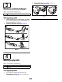
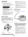
4
InstallingtheGuard
Partsneededforthisprocedure:
1
Guard
3Phillipsheadscrew
Procedure
1.Removethe3Phillipsscrewsthataretapedto
theguardandslidetheguardontothetrimmer
base(AofFigure4).
2.Securetheguardontothebaseofthetrimmer
withthe3Phillipsscrews(BofFigure4).
g195743
Figure4
9

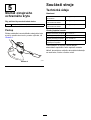
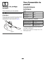
5
InstallingtheEdgeGuard
Partsneededforthisprocedure:
1Wireedgeguard
Procedure
Slightlyspreadtheendsofthewireedgeguardapart
andtheninserttheendsintotheholesinthetrimmer
housingasshowninFigure5.
g189882
Figure5
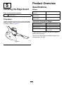
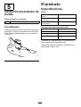
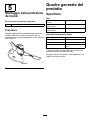
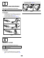
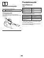
ProductOverview
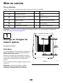
Specications
Weights
Massofthemachinewithout
thebattery
3.2kg(7.0lb)
Massofthemachinewith
battery88525
4.2kg(9.2lb)
Massofthemachinewith
battery88526
4.8kg(10.5lb)
AppropriateTemperatureRanges
Chargethebatteryat0°C(32°F)to40°C(104°F)*
Useproductsat
-15°C(5°F)to60°C(140°F)
Storeproductsat-15°C(5°F)to60°C(140°F)
UnplugthechargerifBelow0°C(32°F)orabove
40°C(104°F)
*Chargingtimewillincreaseifyoudonotchargethe
batterywithinthisrange.
Storethetool,batterypackandbatterychargerinan
enclosedclean,dryarea.
10

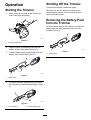
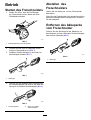
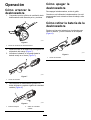
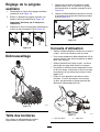
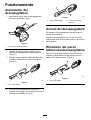
Operation
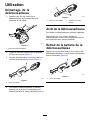
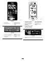
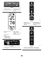
StartingtheTrimmer
1.Makesurethattheventsonthetrimmerare
clearofanydustanddebris.
g194612
Figure6
1.Trimmerventingareas
2.Alignthecavityinthebatterypackwiththe
tongueonthehandlehousing(Figure7).
3.Pushthebatterypackintothehandleuntilthe
batterylocksintothelatch(Figure7).
g189881
Figure7
1.Batterylatch
4.Tostartthetrimmer,pressthelock-outbutton,
thensqueezethevariable-speedtrigger(Figure
8).
g189886
Figure8
1.Lock-outbutton2.Variable-speedtrigger
ShuttingOfftheTrimmer
Toshutoffthetrimmer,releasethetrigger.
Wheneveryouarenotusingthetrimmerorare
transportingthetrimmertoorfromtheworkarea,
removethebatterypack.
RemovingtheBatteryPack
fromtheTrimmer
Pressthebatterylatchonthemachinetoreleasethe
batterypackandslidethebatterypackoutofthe
machine(Figure9).
g192774
Figure9
1.Batterylatch
11

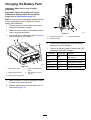
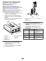
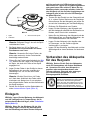
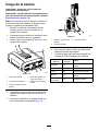
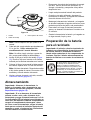
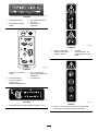
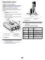
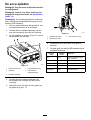
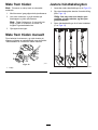
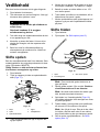
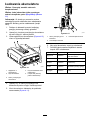
ChargingtheBatteryPack
Important:Makesuretoreadallsafety
precautions.
Important:Chargethebatterypackonlyin
temperaturesthatarewithintheappropriate
range;refertoSpecications(page10).
Note:Atanytime,pressthebattery-charge-indicator
buttononthebatterypacktodisplaythecurrent
charge(LEDindicators).
1.Plugthepowercordthatmatchesyourpower
outletsintothebatterycharger.
2.Makesurethattheventsonthebatterypackare
clearofanydustanddebris.
3.Lineupthecavityinthebatterypack(Figure10)
withthetongueonthecharger.
g228487
Figure10
1.Batterypackcavity4.Battery-charge-indicator
button
2.Batterypackterminals
5.LEDindicators(current
charge)
3.Batterypackventingareas
4.Makesurethattheventsonthebatterycharger
areclearofanydustanddebris.
5.Slidethebatterypackintothechargeruntilitis
fullyseated(Figure11).
g194423
Figure11
1.Chargerventingareas
3.Rightindicatorlight
2.Leftindicatorlight
6.Toremovethebatterypack,slidethebattery
backwardoutofthecharger.
7.RefertothefollowingtabletointerprettheLED
indicatorsonthebatterycharger.
LeftLight
RightLight
Indicates:
Off
Red
Chargerison;nobattery
packinserted
RedRedBatterypackischarging
Green
RedBatterypackischarged
Orange
RedBatterypackistoowarm
RedBlinkingRedReplacethebatterypack
12

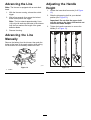
AdvancingtheLine
Note:Thetrimmerisequippedwithanauto-feed
head.
1.Withthetrimmerrunning,releasetheswitch
trigger.
2.Waitafewseconds,thenpressthelockout
buttonandsqueezethetrigger.
Note:Thelineextendsapproximately6mm
(1/4inch)witheachstopandstartofthetrimmer
untilthelinereachesthelengthofthegrass
deectorblade.
3.Resumetrimming.
AdvancingtheLine
Manually
Removethebatteryfromthetrimmer,thenpushthe
buttonatthebaseofthespoolretainerwhilepulling
onthetrimmerlinetomanuallyadvancetheline.
g203810
Figure12
1.Button
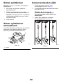
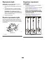
AdjustingtheHandle
Height
1.Loosenthelowershaftconnector(AofFigure
13).
2.Slidethetelescopingshafttoyourdesired
position(BofFigure13).
Important:Donotslidetheuppershaft
overtheventsonthelowershaftanddonot
removetherubberbumper.
3.Tightenthehandleconnectortosecurethe
handle(CofFigure13).
g189876
Figure13
13

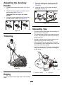
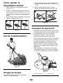
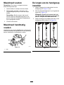
AdjustingtheAuxiliary
Handle
1.Releasetheauxiliary-handlelatch(AofFigure
14).
2.Slidetheauxiliaryhandleupordowntoyour
desiredheight(BofFigure14).
Important:Donotremovetherubber
bumper.
3.Closetheauxiliary-handlelatchtosecurethe
auxiliaryhandleinplace(CofFigure14).
g189875
Figure14
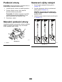
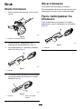
Trimming
g189888
Figure15
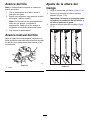
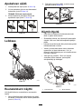
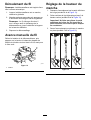
Edging
Tousethetrimmerasanedger,refertothefollowing
steps:
1.Presstherotatorbutton,rotatethehead90°,
andmakesurethatitlocksintoplace(Aof
Figure16).
2.Standthetrimmeronthewheelandbegin
edging(BofFigure16).
g189885
Figure16
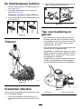
OperatingTips
•Keepthetrimmertiltedtowardtheareabeingcut;
thisisthebestcuttingarea.
•Thestringtrimmercutswhenyoupassitfromleft
toright.Thispreventsthetrimmerfromthrowing
debrisattheyou.
•Usethetipofthestringtodothecutting;donot
forcethestringheadintouncutgrass.
•Wireandpicketfencescauseextrastringwear,
evenbreakage.Stoneandbrickwalls,curbs,and
woodmaywearstringrapidly.
•Avoidtreesandshrubs.Treebark,woodmoldings,
siding,andfencepostscaneasilybedamaged
bythestrings.
g189887
Figure17
1.Directionofrotation2.Stringpath
14

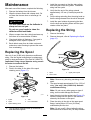
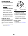
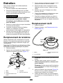
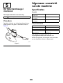
Maintenance
Aftereachuseofthetrimmer,completethefollowing:
1.Removethebatteryfromthetrimmer.
2.Wipethetrimmercleanwithadampcloth.Do
nothosethetrimmerdownorsubmergeitin
water.
CAUTION
Thelinecutoffbladeonthedeectoris
sharpandcancutyou.
Donotuseyourhandstocleanthe
deectorshieldandblade.
3.Wipeorscrapecleanthecuttingheadareaany
timethereisanaccumulationofdebris.
4.Checkandtightenallfasteners.Ifanypartis
damagedorlost,repairorreplaceit.
5.Brushdebrisawayfromairintakeventsand
exhaustonmotorhousingtopreventthemotor
fromoverheating.
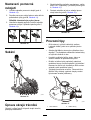
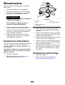
ReplacingtheSpool
Useonly2mm(0.080inch)diametermonolament
string.Usetheoriginalmanufacturer’sreplacement
stringforbestperformance(T oroPartNo.88545TE).
Important:Usingalargerdiameterstringcauses
themotortooverheatandfail.
1.Removethebattery.
2.Pushinthetabsonthesideofthespool
retainingcover(Figure17).
g194053
Figure18
1.Eyelet4.Tabs
2.Spool5.Linecutoffblade
3.Spoolretainingcover
3.Pullthespoolretainingcoveruptoremoveit
andremovethespool.
4.Installthenewspoolsothatthestringaligns
withtheeyeletinthestringhead.Threadthe
stringintotheeyelet.
5.Verifythattheendofthestringextends
approximately152mm(6inches)beyondthe
slot.
6.Pullthestringextendingfromthestringheadso
thatthestringreleasesfromtheslotinthespool.
7.Installthespoolretainerbypressingthetabs
intotheslotsandpushingdownuntilthespool
retainerclicksintoplace.
ReplacingtheString
1.Removethebattery.
2.Removethespool;refertoReplacingtheSpool
(page15).
g015662
Figure19
1.Spool3.Upperpartofspool
2.Anchorhole
Note:Removeanyoldstringremainingonthe
spool.
3.Thespoolacceptsapproximately3.9m(13ft)of
string.Useonly2mm(0.080inch)diameter
monolamentstring.
Note:Donotuseanyothergaugeortypeof
string,asthiscoulddamagethetrimmer.
4.Insertthestringintotheanchorhole(Figure19).
Windthestringontothespoolinthedirection
shownbythearrowsonthespool.
5.Placethestringintheslotontheupperspool
ange,leavingabout152mm(6inches)
extendedbeyondtheslot.
Note:Donotoverll.Afterwindingthestring,
thereshouldbeatleast6mm(1/4inch)between
15
La pagina sta caricando ...
La pagina sta caricando ...
La pagina sta caricando ...
La pagina sta caricando ...
La pagina sta caricando ...
La pagina sta caricando ...
La pagina sta caricando ...
La pagina sta caricando ...
La pagina sta caricando ...
La pagina sta caricando ...
La pagina sta caricando ...
La pagina sta caricando ...
La pagina sta caricando ...
La pagina sta caricando ...
La pagina sta caricando ...
La pagina sta caricando ...
La pagina sta caricando ...
La pagina sta caricando ...
La pagina sta caricando ...
La pagina sta caricando ...
La pagina sta caricando ...
La pagina sta caricando ...
La pagina sta caricando ...
La pagina sta caricando ...
La pagina sta caricando ...
La pagina sta caricando ...
La pagina sta caricando ...
La pagina sta caricando ...
La pagina sta caricando ...
La pagina sta caricando ...
La pagina sta caricando ...
La pagina sta caricando ...
La pagina sta caricando ...
La pagina sta caricando ...
La pagina sta caricando ...
La pagina sta caricando ...
La pagina sta caricando ...
La pagina sta caricando ...
La pagina sta caricando ...
La pagina sta caricando ...
La pagina sta caricando ...
La pagina sta caricando ...
La pagina sta caricando ...
La pagina sta caricando ...
La pagina sta caricando ...
La pagina sta caricando ...
La pagina sta caricando ...
La pagina sta caricando ...
La pagina sta caricando ...
La pagina sta caricando ...
La pagina sta caricando ...
La pagina sta caricando ...
La pagina sta caricando ...
La pagina sta caricando ...
La pagina sta caricando ...
La pagina sta caricando ...
La pagina sta caricando ...
La pagina sta caricando ...
La pagina sta caricando ...
La pagina sta caricando ...
La pagina sta caricando ...
La pagina sta caricando ...
La pagina sta caricando ...
La pagina sta caricando ...
La pagina sta caricando ...
La pagina sta caricando ...
La pagina sta caricando ...
La pagina sta caricando ...
La pagina sta caricando ...
La pagina sta caricando ...
La pagina sta caricando ...
La pagina sta caricando ...
La pagina sta caricando ...
La pagina sta caricando ...
La pagina sta caricando ...
La pagina sta caricando ...
La pagina sta caricando ...
La pagina sta caricando ...
La pagina sta caricando ...
La pagina sta caricando ...
La pagina sta caricando ...
La pagina sta caricando ...
La pagina sta caricando ...
La pagina sta caricando ...
La pagina sta caricando ...
La pagina sta caricando ...
La pagina sta caricando ...
La pagina sta caricando ...
La pagina sta caricando ...
La pagina sta caricando ...
La pagina sta caricando ...
La pagina sta caricando ...
La pagina sta caricando ...
La pagina sta caricando ...
La pagina sta caricando ...
La pagina sta caricando ...
La pagina sta caricando ...
La pagina sta caricando ...
La pagina sta caricando ...
La pagina sta caricando ...
La pagina sta caricando ...
La pagina sta caricando ...
La pagina sta caricando ...
La pagina sta caricando ...
La pagina sta caricando ...
La pagina sta caricando ...
La pagina sta caricando ...
La pagina sta caricando ...
La pagina sta caricando ...
La pagina sta caricando ...
La pagina sta caricando ...
La pagina sta caricando ...
La pagina sta caricando ...
La pagina sta caricando ...
La pagina sta caricando ...
La pagina sta caricando ...
La pagina sta caricando ...
La pagina sta caricando ...
La pagina sta caricando ...
La pagina sta caricando ...
La pagina sta caricando ...
La pagina sta caricando ...
La pagina sta caricando ...
La pagina sta caricando ...
La pagina sta caricando ...
La pagina sta caricando ...
La pagina sta caricando ...
La pagina sta caricando ...
La pagina sta caricando ...
La pagina sta caricando ...
La pagina sta caricando ...
La pagina sta caricando ...
La pagina sta caricando ...
La pagina sta caricando ...
La pagina sta caricando ...
La pagina sta caricando ...
La pagina sta caricando ...
La pagina sta caricando ...
La pagina sta caricando ...
La pagina sta caricando ...
La pagina sta caricando ...
La pagina sta caricando ...
La pagina sta caricando ...
La pagina sta caricando ...
La pagina sta caricando ...
La pagina sta caricando ...
La pagina sta caricando ...
La pagina sta caricando ...
La pagina sta caricando ...
La pagina sta caricando ...
La pagina sta caricando ...
La pagina sta caricando ...
La pagina sta caricando ...
La pagina sta caricando ...
La pagina sta caricando ...
La pagina sta caricando ...
La pagina sta caricando ...
La pagina sta caricando ...
La pagina sta caricando ...
La pagina sta caricando ...
La pagina sta caricando ...
La pagina sta caricando ...
La pagina sta caricando ...
La pagina sta caricando ...
La pagina sta caricando ...
La pagina sta caricando ...
La pagina sta caricando ...
La pagina sta caricando ...
La pagina sta caricando ...
La pagina sta caricando ...
La pagina sta caricando ...
La pagina sta caricando ...
La pagina sta caricando ...
La pagina sta caricando ...
La pagina sta caricando ...
La pagina sta caricando ...
La pagina sta caricando ...
La pagina sta caricando ...
La pagina sta caricando ...
La pagina sta caricando ...
La pagina sta caricando ...
La pagina sta caricando ...
La pagina sta caricando ...
La pagina sta caricando ...
La pagina sta caricando ...
La pagina sta caricando ...
La pagina sta caricando ...
La pagina sta caricando ...
La pagina sta caricando ...
La pagina sta caricando ...
La pagina sta caricando ...
La pagina sta caricando ...
La pagina sta caricando ...
La pagina sta caricando ...
La pagina sta caricando ...
La pagina sta caricando ...
La pagina sta caricando ...
La pagina sta caricando ...
La pagina sta caricando ...
La pagina sta caricando ...
La pagina sta caricando ...
La pagina sta caricando ...
La pagina sta caricando ...
La pagina sta caricando ...
La pagina sta caricando ...
La pagina sta caricando ...
La pagina sta caricando ...
La pagina sta caricando ...
-
 1
1
-
 2
2
-
 3
3
-
 4
4
-
 5
5
-
 6
6
-
 7
7
-
 8
8
-
 9
9
-
 10
10
-
 11
11
-
 12
12
-
 13
13
-
 14
14
-
 15
15
-
 16
16
-
 17
17
-
 18
18
-
 19
19
-
 20
20
-
 21
21
-
 22
22
-
 23
23
-
 24
24
-
 25
25
-
 26
26
-
 27
27
-
 28
28
-
 29
29
-
 30
30
-
 31
31
-
 32
32
-
 33
33
-
 34
34
-
 35
35
-
 36
36
-
 37
37
-
 38
38
-
 39
39
-
 40
40
-
 41
41
-
 42
42
-
 43
43
-
 44
44
-
 45
45
-
 46
46
-
 47
47
-
 48
48
-
 49
49
-
 50
50
-
 51
51
-
 52
52
-
 53
53
-
 54
54
-
 55
55
-
 56
56
-
 57
57
-
 58
58
-
 59
59
-
 60
60
-
 61
61
-
 62
62
-
 63
63
-
 64
64
-
 65
65
-
 66
66
-
 67
67
-
 68
68
-
 69
69
-
 70
70
-
 71
71
-
 72
72
-
 73
73
-
 74
74
-
 75
75
-
 76
76
-
 77
77
-
 78
78
-
 79
79
-
 80
80
-
 81
81
-
 82
82
-
 83
83
-
 84
84
-
 85
85
-
 86
86
-
 87
87
-
 88
88
-
 89
89
-
 90
90
-
 91
91
-
 92
92
-
 93
93
-
 94
94
-
 95
95
-
 96
96
-
 97
97
-
 98
98
-
 99
99
-
 100
100
-
 101
101
-
 102
102
-
 103
103
-
 104
104
-
 105
105
-
 106
106
-
 107
107
-
 108
108
-
 109
109
-
 110
110
-
 111
111
-
 112
112
-
 113
113
-
 114
114
-
 115
115
-
 116
116
-
 117
117
-
 118
118
-
 119
119
-
 120
120
-
 121
121
-
 122
122
-
 123
123
-
 124
124
-
 125
125
-
 126
126
-
 127
127
-
 128
128
-
 129
129
-
 130
130
-
 131
131
-
 132
132
-
 133
133
-
 134
134
-
 135
135
-
 136
136
-
 137
137
-
 138
138
-
 139
139
-
 140
140
-
 141
141
-
 142
142
-
 143
143
-
 144
144
-
 145
145
-
 146
146
-
 147
147
-
 148
148
-
 149
149
-
 150
150
-
 151
151
-
 152
152
-
 153
153
-
 154
154
-
 155
155
-
 156
156
-
 157
157
-
 158
158
-
 159
159
-
 160
160
-
 161
161
-
 162
162
-
 163
163
-
 164
164
-
 165
165
-
 166
166
-
 167
167
-
 168
168
-
 169
169
-
 170
170
-
 171
171
-
 172
172
-
 173
173
-
 174
174
-
 175
175
-
 176
176
-
 177
177
-
 178
178
-
 179
179
-
 180
180
-
 181
181
-
 182
182
-
 183
183
-
 184
184
-
 185
185
-
 186
186
-
 187
187
-
 188
188
-
 189
189
-
 190
190
-
 191
191
-
 192
192
-
 193
193
-
 194
194
-
 195
195
-
 196
196
-
 197
197
-
 198
198
-
 199
199
-
 200
200
-
 201
201
-
 202
202
-
 203
203
-
 204
204
-
 205
205
-
 206
206
-
 207
207
-
 208
208
-
 209
209
-
 210
210
-
 211
211
-
 212
212
-
 213
213
-
 214
214
-
 215
215
-
 216
216
-
 217
217
-
 218
218
-
 219
219
-
 220
220
-
 221
221
-
 222
222
-
 223
223
-
 224
224
-
 225
225
-
 226
226
-
 227
227
-
 228
228


Toro PowerPlex 33cm 40V MAX String Trimmer Manuale utente
- Categoria
- Tagliaerba
- Tipo
- Manuale utente
in altre lingue
- français: Toro PowerPlex 33cm 40V MAX String Trimmer Manuel utilisateur
- Deutsch: Toro PowerPlex 33cm 40V MAX String Trimmer Benutzerhandbuch
- Nederlands: Toro PowerPlex 33cm 40V MAX String Trimmer Handleiding
- dansk: Toro PowerPlex 33cm 40V MAX String Trimmer Brugermanual
- polski: Toro PowerPlex 33cm 40V MAX String Trimmer Instrukcja obsługi
- eesti: Toro PowerPlex 33cm 40V MAX String Trimmer Kasutusjuhend
- svenska: Toro PowerPlex 33cm 40V MAX String Trimmer Användarmanual
Documenti correlati
-
Toro PowerPlex 33cm 40V MAX String Trimmer/Edger Manuale utente
-
-
-
-
-
-
-
Toro PowerPlex 40V Max Standard 90 WH Battery Pack Manuale utente
-
-