Yamaha NS-P270 Manuale del proprietario
- Categoria
- Subwoofer
- Tipo
- Manuale del proprietario
Questo manuale è adatto anche per

YAMAHA ELECTRONICS CORPORATION, USA
6660 ORANGETHORPE AVE., BUENA PARK, CALIF. 90620, U.S.A.
YAMAHA CANADA MUSIC LTD.
135 MILNER AVE., SCARBOROUGH, ONTARIO M1S 3R1, CANADA
YAMAHA ELECTRONIK EUROPA G.m.b.H.
SIEMENSSTR. 22-34, 25462 RELLINGEN BEI HAMBURG, GERMANY
YAMAHA ELECTRONIQUE FRANCE S.A.
RUE AMBROISE CROIZAT BP70 CROISSY-BEAUBOURG 77312 MARNE-LA-VALLEE CEDEX02, FRANCE
YAMAHA ELECTRONICS (UK) LTD.
YAMAHA HOUSE, 200 RICKMANSWORTH ROAD WATFORD, HERTS WD18 7GQ, ENGLAND
YAMAHA SCANDINAVIA A.B.
J A WETTERGRENS GATA 1, BOX 30053, 400 43 VÄSTRA FRÖLUNDA, SWEDEN
YAMAHA MUSIC AUSTRALIA PTY, LTD.
17-33 MARKET ST., SOUTH MELBOURNE, 3205 VIC., AUSTRALIA
©
2006 All rights reserved.
Printed in China WG84260
(NS-P270 / NS-P276: NX-E270 + NX-C270 + SW-P270)
G
OWNER'S MANUAL
MODE D'EMPLOI
BEDIENUNGSANLEITUNG
BRUKSANVISNING
MANUALE DI ISTRUZIONI
MANUAL DE INSTRUCCIONES
GEBRUIKSAANWIJZING
000_cv_NS-P270_276_G.fm Page 1 Friday, December 2, 2005 9:55 AM

i
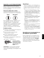
Precautions
1 To assure the finest performance, please read this manual
carefully. Keep it in a safe place for future reference.
2 Install the speakers in a cool, dry, clean place – away from
windows, sources of heat, sources of excessive vibration,
dust, moisture or cold. Avoid sources of electrical
humming (e.g., transformers and motors). To prevent fire or
electric shock, do not expose the speakers to rain or water.
3 To prevent the enclosure from warping or discoloring, do
not expose the speakers to direct sunlight or excessive
humidity.
4 Avoid installing the speakers where foreign objects may
fall onto them and/or where they may be exposed to liquid
dripping or splashing.
5 Do not place the following objects on top of the speakers:
– Other components, as they might damage or discolor
the surface of the speakers.
– Burning objects (e.g., candles), as they might cause fire,
damage to the speakers or personal injury.
– Containers of liquid, as they might spill and cause
electric shock to the user or damage to the speakers.
6 Do not place the speakers where they are liable to be
knocked over or struck by falling objects. Stable placement
will also ensure better sound performance.
7 Placing the speakers on the same shelf or rack as the
turntable can result in feedback.
8
Secure placement or installation is the owner’s responsibility.
YAMAHA
is not liable for accidents caused by improper
placement or installation of speakers.
9 Any time you note distortion, reduce the volume control on
your amplifier to lower setting. Never allow your amplifier
to be driven into “clipping”. Otherwise, the speakers may
be damaged.
10 When using an amplifier with a rated output power higher
than the nominal input power of the speakers, care should
be taken not to exceed the maximum input of the speakers.
11 Do not attempt to clean the speakers with chemical solvents
as this might damage the finish. Use a clean, dry cloth.
12 Do not attempt to modify or fix the speakers. Contact
qualified YAMAHA service personnel when service is
needed. The cabinet should never be opened for any reason.
13 Be sure to read the “Troubleshooting” section regarding
common operating errors before concluding that the
speakers are faulty.
For SW-P270
1 Do not operate this unit upside down. It may overheat,
possibly causing damage.
2 Do not use excessive force on switches, controls or
connection wires. When moving this unit, first disconnect
the power plug and the wires connected to other equipment.
Never pull the wires themselves.
3 Since this unit has a built-in power amplifier, heat radiates
from the rear panel. Place the unit away from walls,
allowing at least 20 cm of space above, behind and on both
sides of the unit to prevent fire or damage. Furthermore, do
not position the unit with the rear panel facing down on the
floor or other surfaces.
4 When using a humidifier, be sure to avoid condensation
inside this unit by allowing enough space around the unit
and avoiding excess humidification. Condensation might
cause fire, damage to the unit, and/or electric shock.
5 Do not cover the rear panel of this unit with a newspaper,
tablecloth, curtain, etc. to avoid obstructing heat radiation.
If the temperature inside the unit rises, it may cause fire,
damage to the unit, or personal injury.
6 Do not plug this unit into a wall outlet until all connections
are complete.
7 The voltage to be used must match that specified on the
rear panel. Using this unit with a voltage higher than
specified is dangerous and may cause fire, damage to the
unit, and/or personal injury. YAMAHA is not responsible
for damage resulting from use of this unit with a voltage
other than specified.
8 Super-bass sound reproduced by this unit may cause a
turntable to generate audio feedback. In this case, move the
unit away from the turntable.
9 This unit may be damaged if certain sounds are
continuously output at high volume level. For example, if
20 Hz–50 Hz sine waves from a test disc or bass sounds
from an electronic instrument, etc. are continuously output,
or if a turntable stylus touches the surface of a disc, reduce
the volume level to prevent the unit from being damaged.
10 If you hear distorted noise (i.e., unnatural, intermittent
“rapping” or “hammering” sounds) from this unit, reduce
the volume level. Extremely loud movie soundtrack low
frequency, bass-heavy sounds, or similarly loud popular
music passages can damage this unit.
11 Vibration generated by super-bass sound may distort
images on a TV. In this case, move the unit away from the
TV set.
12 When disconnecting the power cord from the wall outlet,
grasp the plug; do not pull the cord.
13 When you plan not to use this unit for a long period of time
(i.e. vacation, etc.), disconnect the AC power plug from the
wall outlet.
14 Install this unit near the wall outlet and where the AC
power plug can be reached easily.
This unit features a magnetically shielded design, but there
is still a chance that placing it too close to a TV set might
impair picture color. Should this happen, move this unit
away from the TV set.
As long as this unit is connected to the AC wall outlet, it is
not disconnected from the AC power source even if you turn
off this unit by POWER.

1
English
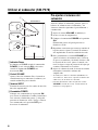
• VOLTAGE SELECTOR
(For China, Korea, Asia and General models)
The voltage selector switch on the rear panel of this unit must be set for your local main voltage BEFORE
plugging this unit into the AC main supply. Voltages are 110-120/220-240 V AC, 50/60 Hz.
Table of contents
Precautions . . . . . . . . . . . . . . . . . . . . . . . . . . . . . . . . . . . . . . . . . . . . i
Introduction . . . . . . . . . . . . . . . . . . . . . . . . . . . . . . . . . . . . . . . . . . . . 2
Package contents. . . . . . . . . . . . . . . . . . . . . . . . . . . . . . . . . . . . . . . . . . . . . . . . . . . . . . . . . 2
Setting up the speakers . . . . . . . . . . . . . . . . . . . . . . . . . . . . . . . . . . . . 3
Positioning the front and surround speakers (NX-E270) . . . . . . . . . . . . . . . . . . . . . . . . . . . 3
Positioning the center speaker (NX-C270). . . . . . . . . . . . . . . . . . . . . . . . . . . . . . . . . . . . . . 4
Positioning the subwoofer (SW-P270) . . . . . . . . . . . . . . . . . . . . . . . . . . . . . . . . . . . . . . . . 4
Mounting the front and surround speakers . . . . . . . . . . . . . . . . . . . . . . . . . . . . . . . . . . . . . 5
Connections . . . . . . . . . . . . . . . . . . . . . . . . . . . . . . . . . . . . . . . . . . . . 6
Basic connection example . . . . . . . . . . . . . . . . . . . . . . . . . . . . . . . . . . . . . . . . . . . . . . . . . . 6
Connecting speaker cables . . . . . . . . . . . . . . . . . . . . . . . . . . . . . . . . . . . . . . . . . . . . . . . . . 7
Connecting components and the subwoofer to AC power . . . . . . . . . . . . . . . . . . . . . . . . . . 7
Using the subwoofer (SW-P270) . . . . . . . . . . . . . . . . . . . . . . . . . . . . . . 8
Pre-adjusting the subwoofer volume . . . . . . . . . . . . . . . . . . . . . . . . . . . . . . . . . . . . . . . . . . 8
Advanced YAMAHA Active Servo Technology (on the SW-P270). . . . . . . . .9
Troubleshooting . . . . . . . . . . . . . . . . . . . . . . . . . . . . . . . . . . . . . . . . 10
Specifications . . . . . . . . . . . . . . . . . . . . . . . . . . . . . . . . . . . . . . . . . 11
Frequency characteristics . . . . . . . . . . . . . . . . . . . . . . . . . . . . . . . . . . . . . . . . . . . . . . . . . 11

2
Introduction
Thank you for choosing a YAMAHA NS-P270 or NS-P276 Home Cinema 5.1/6.1 Channel Speaker System.
Each of these systems includes the following speakers:
• NX-E270
The NX-E270 are full-range acoustic-suspension speakers. Each system includes two (2) front and two
(2) surround speakers. In addition, the NS-P276 system includes an additional NX-E270 that serves as a
surround back speaker.
•NX-C270
The NX-C270 is a full-range acoustic-suspension center speaker.
•SW-P270
The SW-P270 is a subwoofer that features a built-in power amplifier. It utilizes Advanced YAMAHA
Active Servo Technology to reproduce extremely high quality super-bass range sounds that add a rich,
realistic dimension to your home theater. (Refer to page 9 for detailed information on Advanced
YAMAHA Active Servo Technology.)
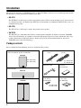
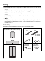
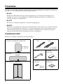
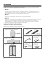
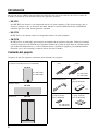
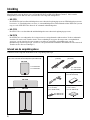
Package contents
Please confirm that the following items are included in the package.
Front and surround speakers
(and surround back speaker in NS-P276)
Center speaker
Subwoofer
NX-E270
X 4 <NS-P270>
X 5 <NS-P276>
NX-C270
SW-P270
Speaker cables
Subwoofer cable Fasteners
(for NX-C270)
Non-skid pads
[1 set, 8 pcs]
(for NX-E270)
Non-skid pads
[1 set, 4 pcs]
(for SW-P270)
X 2
[4 m]
X2 <NS-P270>
X3 <NS-P276>
X 2 <NS-P270>
X 3 <NS-P276>
[10 m]
X 3

3
English
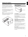
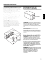
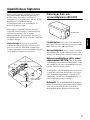
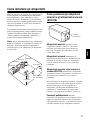
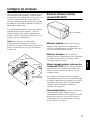
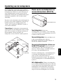
Setting up the speakers
Before you connect the speakers, place each
speaker in its respective location. Speaker
positioning is very important as it affects the
overall sound quality of the system. Place the
speakers in locations that will optimize the sound
quality at your listening position. Refer to the
illustration below.
The position of the subwoofer is not as critical as
the position of the other speakers because low bass
tones are not highly directional. Refer to
“Positioning the subwoofer (SW-P270)” on page 4
for more information.
Note: These speakers are magnetically shielded.
However, if you place them too close to a TV, they
may impair picture color. In this case, move the
speakers further away from the TV.
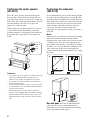
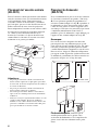
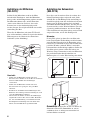
Positioning the front and surround
speakers (NX-E270)
Front speakers: Place the two front speakers on
the left and right sides of the TV, at approximately
the same height as the TV, facing directly forward.
Surround speakers: Place the left and right
surround speakers behind your listening position,
facing slightly inward, about 1.8 m (approx. 6 feet)
above the floor.
Surround back speaker (for NS-P276
systems only): Position the surround back
speaker behind your listening position, precisely
between the surround speakers, about 1.8 m
(approx. 6 feet) above the floor.
You can set the front, surround, and surround back
speakers on tables or other supports, or mount
them on a wall or speaker stand. (For more
information, see “Mounting the front and surround
speakers” on page 5.)
Non-skid pads: When placing the speakers on a
flat surface, attach the included non-skid pads to
the corners of the speaker bottoms, as shown
above. The non-skid pads will prevent the speakers
from sliding.
Center
Front R
Subwoofer
TV-set
Front L
Surround back
(for NS-P276)
Surround R
Surround L
Non-skid pad

4
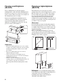
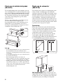
Positioning the center speaker
(NX-C270)
Place the center speaker precisely between the
front speakers, facing directly forward. You can
place the center speaker on top of a TV (if the top
of the TV is flat), on the floor beneath the TV, or in
an entertainment center. Be sure to place the
speaker in a stable location.
When placing the speaker on top of a TV rack, etc.,
to prevent the speaker from falling, attach the
provided fasteners at two points on the bottom of
the speaker and on top of the TV, as illustrated
below.
Cautions:
• Do not place the center speaker on a TV that has a top
surface area smaller than the speaker bottom.
Otherwise, the speaker may fall and cause injury.
• Do not place the center speaker on a TV that has a
slanted or inclined top.
• Do not touch the adhesive surface of a fastener after
you peel off the seal, as this will weaken the adhesive
strength of the fastener.
• Thoroughly wipe to clean the surface where the
fastener is to be applied. Note that adhesive strength
will be weakened if the surface is dirty, oily or wet.
Weakened adhesive may cause the center speaker to
fall.
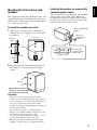
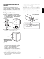
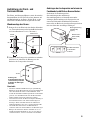
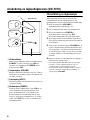
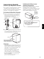
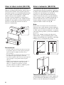
Positioning the subwoofer
(SW-P270)
It is recommended to place it on the outside of either
the right or the left front speaker. (See fig.
A
.) The
placement shown in fig.
B
is also possible, however,
if the subwoofer system is placed directly facing the
wall, the bass effect may lessen because the sound
from it and the sound reflected by the wall may
cancel out each other. To prevent this from
happening, face the subwoofer system at an angle as
in fig.
A.
Note:
There may be a case that you cannot obtain enough
super-bass sounds from the subwoofer when
listening in the center of the room. This is because
"standing waves" have been developed between
two parallel walls and they cancel the bass sounds.
In such a case, face the subwoofer obliquely to the
wall. It also may be necessary to break up the
parallel surfaces by placing bookshelves etc. along
the walls.
Non-skid pads: Place the included non-skid
pads at the four corners of the bottom of the
subwoofer to prevent the subwoofer from sliding
due to vibration or minor impact.
Peel off
the
seal.
AB
: Subwoofer : Front speaker

5
English
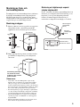
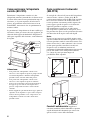
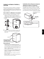
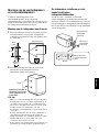
Mounting the front and surround
speakers
You can place the front and surround speakers (and
surround back speaker in an NS-P276 system) on a
shelf or rack, set them on the floor, or mount them
on a wall or speaker stand.
To mount the speakers on a wall:
1.Affix screws to a firm wall or wall support as
shown below. (Use tapping screws 3.5 to 4mm
in diameter.)
2.Suspend the speaker by mounting the holes in
the speaker’s rear panels on the protruding
screws.
Cautions
:
• Each front or surround speaker weighs 0.8 kg
(1.8 lbs.). Do not mount the speakers on thin plywood
or on a wall made of soft surface material. Otherwise,
the screws may pull out of the surface and the
speakers may fall, possibly damaging the speakers or
causing personal injury.
• Do not affix the speakers to a wall using nails,
adhesives, or unstable hardware. Long term use and
vibration may cause the speakers to fall.
• To avoid accidents resulting from tripping over loose
speaker cables, affix the cables to the wall.
• Mount the speakers in a wall location that will be
unlikely to result in injury to an individual’s head.
Installing the speakers on commercially
available speaker stands:
You can mount the front, surround, and surround
back speakers on a speaker stand. When you
installing the speaker on commercially available
speaker stand, you need to attach a bracket to the
bottom of the speaker using a screw.
Holes
10 mm
Minimum
20 mm
70 mm
70 mm
Wall/ wall
support
Rear view
Note: Make sure that the
screws are securely affixed in
the narrow part of the holes.
70 mm
Insert only M4
screws through the
outside holes.
60 mm (2-3/8”)
Bracket (AAX34790)
(option)
M4 screw
(AAX12390)
(option)

6
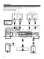
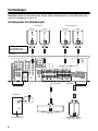
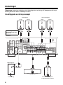
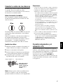
Connections
Caution: Plug the power cables for the subwoofer and other audio/video components into an AC
outlet only after you complete all other connections.
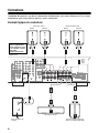
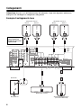
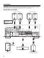
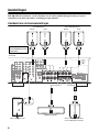
Basic connection example
To AC outlet
Center speaker
Surround back speaker
(in NS-P276 systems)
Subwoofer
Amplifier
Front speakers
Surround speakers
Right
Right
Left
Left
Note: The rear panel
of various amplifiers
may differ in
appearance.

7
English
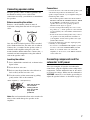
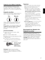
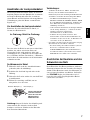
Connecting speaker cables
Keep the speaker cables as short as possible. Do
not bundle or roll up excess cable. If the
connections are faulty, you will hear no sound from
the speakers.
Before connecting the cables:
Remove a small amount (about 10 mm) of
insulation coating from the end of each speaker
cable.
One side of the included speaker cable is marked
with a broken white line; the other side is unlined.
Connect the (+) terminal on the speaker to the (+)
terminal on the amplifier using the cable side
marked with the broken white line. Connect the (–)
terminals on both components using the unlined
side of the speaker cable.
Inserting the cables:
1.Press and hold the terminal tab, as shown in the
figure below.
2.Insert the bare wire core.
3.Release your finger from the tab to allow it to
lock securely on the bare wire core.
4.Test the security of the connection by pulling
gently on the cable at the terminal.
Note: Do not let uninsulated bare wires touch each
other as this could damage the speaker or the
amplifier.
Connections:
• Connect the front, center and surround speakers (and
surround back speaker for the NS-P276) to the
speaker output terminals on your amplifier using the
included speaker cables.
– The included speaker cables have labels marked
FRONT L, FRONT R, CENTER, REAR L, REAR
R (and REAR C for NS-P276). Connect each
speaker cable to the corresponding speaker as
illustrated in the figure on page 6.
– Connect each speaker making sure not to reverse
the polarity (+, –). If the speaker is connected with
reversed polarity, the sound will be unnatural and
lack bass.
– For the front and surround speakers only, connect
one speaker to the left (marked L) terminals on
your amplifier, and the other speaker to the right
(marked R) terminals.
• Connect the subwoofer to the line output (pin jack)
terminal(s) on the amplifier.
– To connect to a YAMAHA DSP amplifier (or AV
receiver), connect the SUBWOOFER (or LOW
PASS, etc.) terminal on the rear of the DSP
amplifier (or AV receiver) to the INPUT terminal
on the subwoofer.
Connecting components and the
subwoofer to AC power
After you complete all speaker and subwoofer
connections, plug the amplifier, other audio/video
components, and the subwoofer into an AC outlet
of appropriate voltage. Make sure the subwoofer’s
VOLUME control is set to 0 before proceeding to
adjust the speaker balance as described on page 8.
Good
Not Good
3
1
2
Red: positive (+)
Black: negative (–)
Note: Do not insert
the insulation
coating into the
hole. The sound
may not be
produced.

8
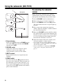
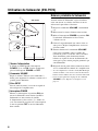
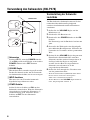
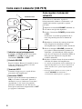
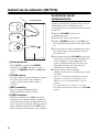
Using the subwoofer (SW-P270)
1Power indicator
Lights up in GREEN when the POWER switch
4 is turned ON; turns off when the POWER
switch is turned OFF.
2VOLUME control
Adjusts the volume level. Turn the control
clockwise to increase the volume, and
counterclockwise to decrease the volume.
3INPUT terminal
Input terminal for line level signals from the
amplifier.
4POWER switch
Press this switch to the ON position to turn on
the power to the subwoofer. When the power of
the subwoofer is on, the power indicator 1 on
the rear panel lights up green. Press this switch
again to set it to the OFF position to turn off the
power of the subwoofer.
Pre-adjusting the subwoofer
volume
Before you use the subwoofer, first adjust the
volume balance between the subwoofer and the
front speakers by following the procedure below.
1.Set the VOLUME control to minimum (0).
2.Turn on the power to all other components.
3.Press the POWER switch to the ON position.
The power indicator on the rear panel lights up
in green.
4.Play a source that contains low-frequency
sounds. Adjust the amplifier’s volume control to
the desired listening level.
5.Rotate the VOLUME control gradually to adjust
the volume balance between the subwoofer and
the other speakers. In most cases, set the control
to a level at which you hear slightly more bass
than when the subwoofer is not used.
6.Adjust the volume of the entire sound system
using the amplifier’s volume control.
• If you replace the front speakers (NX-E270) with
other speakers, you must again balance the subwoofer
and surround speaker volume.
• For more information on adjusting the VOLUME
control, refer to “Frequency characteristics” on
page 11.
O
FF
P
O
W
E
R
O
N
4
V
O
L
UM
E
2
1
3
I
NPU
T
Rear panel

9
English
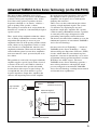
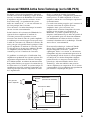
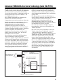
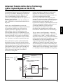
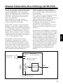
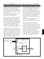
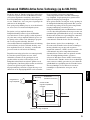
Advanced YAMAHA Active Servo Technology (on the SW-P270)
The theory behind YAMAHA Active Servo
Technology is based on two factors: the Helmholtz
resonator and negative-impedance drive. Active
Servo Processing speakers reproduce the bass
frequencies through an “air woofer,” which is a
port or opening in the speaker’s cabinet.
This opening is used instead of, and performs the
functions of, a woofer in a conventionally designed
speaker system.
Thus, signals of low amplitude within the cabinet
can, according to Helmholtz resonance theory, be
output from this opening as waves of great
amplitude if the size of the opening and the volume
of the cabinet are in proportion to satisfy a certain
ratio. In order to accomplish this, moreover, the
amplitudes within the cabinet must be both precise
and of sufficient power because these amplitudes
must overcome the “load” presented by the air in
the cabinet.
This problem is resolved by a design in which the
amplifier supplies special signals. If the electrical
resistance of the voice coil could be reduced to
zero, the movement of the speaker unit would
become linear with respect to signal voltage. To
accomplish this, the system utilizes a special
negative-impedance output-drive amplifier that
subtracts the output impedance of the amplifier.
By employing negative-impedance drive circuits,
the amplifier is able to generate precise, low-
amplitude, low frequency waves with superior
damping characteristics.
These waves are then radiated from the cabinet
opening as high-amplitude signals. The system
can, therefore, by employing the negative-
impedance output drive amplifier and a speaker
cabinet featuring a Helmholtz resonator, reproduce
an extremely wide range of frequencies with
outstanding sound quality and low distortion.
The features described above combine to create the
fundamental structure of conventional YAMAHA
Active Servo Technology.
Our new Active Servo Technology — Advanced
YAMAHA Active Servo Technology — adopts
Advanced Negative Impedance Converter (ANIC)
circuits, which allow the conventional negative
impedance converter to dynamically vary to select
an optimum value for speaker impedance variation.
With these new ANIC circuits, Advanced
YAMAHA Active Servo Technology provides a
more stable performance and improved sound
pressure compared to conventional YAMAHA
Active Servo Technology, resulting in more natural
and dynamic bass reproduction.
High-amplitude
bass sound
Cabinet
Port
Air woofer
(Helmholtz resonator)
Advanced Negative
impedance Converter
Active Servo
Processing
Amplifier
Signals of low amplitude
Signals

10
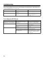
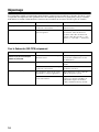
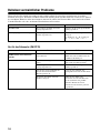
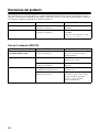
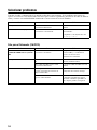
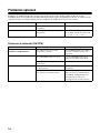
Troubleshooting
Refer to the chart below if the unit does not function properly. If the problem you are experiencing is not
listed, or if the instructions fail to help you resolve the problem, disconnect the power cord and contact your
authorized YAMAHA dealer or service center.
For the Subwoofer (SW-P270) only
Problem Cause What to Do
No sound.
Speaker cables are not connected
securely.
Connect the speaker cables securely.
Sound level is too low.
Speaker cables are not connected
correctly.
Connect the speaker cables correctly:
L (left) to L, R (right) to R, “+” to
“+” and “–” to “–”.
Problem Cause What to Do
Power is not supplied even though the
POWER switch is set to the ON position.
The power plug is not securely
connected.
Turn the power switch OFF, then
connect the power plug securely.
No sound.
The VOLUME control is set to 0. Turn the VOLUME control to the
right (clockwise).
The subwoofer cable is not connected
securely.
Connect the subwoofer cable
securely.
Sound level is too low.
You are playing a sound source that
includes inadequate bass frequencies.
Play a sound source that includes
more bass frequencies.
The sound level has been diminished
by standing waves.
Reposition the subwoofer, or break
up the parallel wall surface by placing
bookshelves or other large objects
along the wall.

11
English
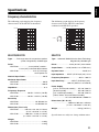
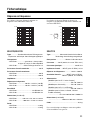
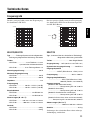
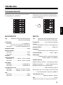
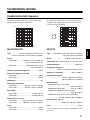
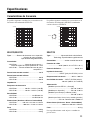
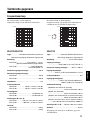
Specifications
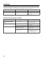
Frequency characteristics
The following graph displays the frequency
characteristics of the SW-P270 subwoofer.
The following graph displays the frequency
characteristics of the SW-P270 subwoofer
combined with NX-E270 speakers.
NX-E270/NX-C270
Type .........Full-range acoustic-suspension speaker
system, Magnetically shielded type
Driver
<NX-E270> .....................8 cm (8-5/32”) woofer +
1.9 cm (3/4”) balanced-dome tweeter
<NX-C270>
.............................. 5 cm (2") full-range
cone speaker x 2
Nominal Input Power.....................................30 W
Maximum Input Power
<NX-E270> ................................................. 80 W
<NX-C270> ................................................100 W
Impedance........................................................ 6 Ω
Frequency Response
<NX-E270> ................ 100 Hz – 25 kHz (–10 dB)
<NX-C270> .................130 Hz – 20 kHz (–10 dB)
Sensitivity
<NX-E270> ................................. 85 dB/2.83 Vm
<NX-C270> .................................. 85 dB/2.83 Vm
Dimensions (W x H x D)
<NX-E270> ........... 105 mm x 151 mm x 113 mm
(4-1/8” x 5-15/16” x 4-7/16”)
<NX-C270> ..............300 mm x 72 mm x 113 mm
(11-13/16” x 2-27/32” x 4-7/16”)
Weight
<NX-E270> ................................................ 0.8 kg
<NX-C270> ................................................ 0.9 kg
SW-P270
Type
... Advanced
YAMA H A
Active Servo Technology
Magnetically shielded type
Driver .........................16 cm (6-5/16") cone woofer
Output Power
......... 50 W (100 Hz, 5
Ω
at THD=10%)
Dynamic Power
........................................ 100 W, 5
Ω
Input Impedance
...... INPUT (1P RCA pin jack): 12 k
Ω
Frequency Response ................... 30 Hz – 200 Hz
Input Sensitivity
................INPUT (1P RCA pin jack):
100 mV (100 Hz, 5 Ω at 50 W)
Power Supply
[U.S.A. and Canada models] ......AC 120 V, 60 Hz
[Australia model].........................AC 240 V, 50 Hz
[U.K. and Europe models] ..........AC 230 V, 50 Hz
[China, Korea, Asia and General models]
........................ AC 110-120/220-240 V, 50/60 Hz
Dimensions (W x H x D)
.............................. 200 mm x 365 mm x 370 mm
(7-7/8” x 143-23/32” x 14-9/16”)
Weight .......................................... 8.5 kg (18.7 lbs.)
Specifications are subject to change without notice.
20 50 100 200 500 Hz
40
50
60
70
80
90
100 dB
20 50 100 200 500 Hz
40
50
60
70
80
90
100 dB
SW-P270
NX-E270
V
O
L
UM
E

i
Précautions
1 Pour profiter au mieux de votre acquisition, lisez attentivement
ce mode d’emploi. Conservez-le soigneusement pour référence.
2 Installez les enceintes dans un endroit frais, sec, loin des fenêtres
et des sources de chaleur et de vibration, des poussières, de
l’humidité et du froid. Évitez les sources de ronflements
électriques que sont les transformateurs et les moteurs. Pour
éviter les risques d’incendie et de secousses électriques,
n’exposez pas les enceintes à la pluie ni à l’humidité.
3 Pour éviter que la menuiserie des enceintes ne se déforme
ou ne se décolore, n’exposez pas les enceintes à la lumière
directe du soleil ni à une humidité excessive.
4 Évitez d’installer les enceintes dans un endroit exposé à la
chute d’objets ou encore à l’écoulement ou aux
éclaboussures de liquides.
5 Ne posez pas les objets suivants sur le dessus des enceintes:
– D’autres appareils qui pourraient endommager ou
décolorer la menuiserie des enceintes;
– Des objets enflammés (par exemple, des bougies) qui
pourraient endommager les enceintes, provoquer une
blessure, voire un incendie;
– Des récipients contenant des liquides qui pourraient se
renverser, endommager les enceintes ou être à l’origine
d’une secousse électrique.
6 Ne placez pas les enceintes dans un endroit où elles
peuvent être heurtées, directement ou par la chute d’objets.
Un emplacement stable garantit l’obtention de meilleures
sonorités.
7 Placer les enceintes sur des étagères ou dans un meuble qui
contient également la platine de lecture, peut entraîner un
phénomène de bouclage.
8 La détermination d’un endroit convenable est de votre
responsabilité. YAMAHA ne saurait être responsable des
accidents provoqués par le choix d’un emplacement qui ne
conviendrait pas, ni par l’installation incorrecte des enceintes.
9 En cas de distorsion, réduisez le niveau de sortie de
l’amplificateur. N’excitez pas l’amplificateur au point qu’il
écrête. Dans ce cas en effet, les enceintes pourraient être
endommagées.
10 Vous devez être très attentif, si l’amplificateur peut délivrer
une puissance supérieure à la puissance maximale admissible
par les enceintes, à ce que cela ne se produise pas.
11 Ne nettoyez pas la menuiserie des enceintes avec un produit
chimique qui peut endommager leur finition. Utilisez un
chiffon sec et propre.
12 Ne tentez pas de modifier les enceintes ni de les réparer.
Consultez le service YAMAHA compétent si une
réparation est nécessaire. Pour quelque raison que ce soit,
ne démontez pas la menuiserie des enceintes.
13 Prenez connaissance des erreurs fréquentes, mentionnées
dans la section “Dépannage”, avant de conclure que les
enceintes sont défectueuses.
En ce qui concerne le SW-P270
1 Ne le faites pas fonctionner à l’envers. Il peut surchauffer et
être endommagé.
2 Manœuvrez les commutateurs et les commandes avec
précaution, veillez aux câbles de liaison. Avant de déplacer
cet appareil, débranchez la fiche du cordon d’alimentation
et les câbles qui le relient aux autres appareils. Ne tirez pas
sur les câbles.
3 Cet appareil étant doté d’un amplificateur de puissance, il
rayonne de la chaleur, à travers son panneau arrière. Placez
cet appareil loin des murs et ménagez au moins 20 cm
au-dessus, derrière et sur chaque côté pour réduire les
risques d’incendie ou d’endommagement. Par ailleurs, ne
positionnez pas cet appareil de telle manière que son
panneau arrière soit tourné vers le plancher ou en contact
avec une paroi.
4 Si vous utilisez un humidificateur, veillez à réduire les
risques de condensation à l’intérieur de cet appareil en
ménageant suffisamment d’espace libre autour de lui et en
réglant l’humidificateur à une valeur convenable. La
condensation peut provoquer un incendie, endommager
l’appareil et/ou être la cause d’une secousse électrique.
5 Ne couvrez pas le panneau arrière d’un journal, d’une
nappe, d’un rideau, etc., ce qui pourrait empêcher la
chaleur de s’évacuer. Une augmentation anormale de la
température intérieure de l’appareil peut provoquer un
incendie, endommager l’appareil ou entraîner des
blessures.
6 Ne branchez pas la fiche du cordon d’alimentation sur une
prise secteur aussi longtemps que tous les raccordements ne
sont pas terminés.
7 La tension à utiliser est indiquée sur le panneau arrière.
Alimenter cet appareil sous une tension supérieure à la
tension prescrite, peut provoquer un incendie, endommager
l’appareil et/ou entraîner des blessures. YAMAHA ne
saurait être responsable des dommages résultant de
l’utilisation d’une tension d’alimentation différente de la
tension prescrite.
8 Le son à fréquences très graves produites par cet appareil
peut agir sur la platine de lecture et provoquer un bouclage.
Dans ce cas, éloignez l’appareil de la platine de lecture.
9 Cet appareil peut être endommagé par la production
permanente de certaines fréquences. Par exemple, si un
signal sinusoïdal entre 20 et 50 Hz est produit par un disque
d’essai ou des sons très graves sont générés par un
instrument de musique électronique, etc., ou encore si le
saphir de la platine de lecture frotte sur le microsillon, il
sera bon de réduire le niveau de sortie pour éviter les
dommages.
10 Si vous notez que cet appareil produit de la distorsion (par
exemple, des bruits secs et répétés, un martèlement),
réduisez le niveau de sortie. Les fréquences très graves que
contiennent certaines pistes sonores de film ou certains
passages de musique populaire, peuvent endommager cet
appareil.
11 Les vibrations produites par le son à fréquences très graves
peuvent déformer les images affichées sur le téléviseur.
Dans ce cas, éloignez l’appareil du téléviseur.
12 Pour débrancher la fiche du cordon d’alimentation,
saisissez la fiche mais ne tirez pas sur le cordon.
13 Si vous envisagez de ne pas utiliser cet appareil pendant
une longue période (par exemple, pendant des congés),
débranchez la fiche du cordon d’alimentation au niveau de
la prise secteur.
14 Installez l’appareil près de la prise secteur et à un endroit
tel que la fiche secteur soit facilement accessible.
Même si cette unité dispose d’une conception à blindage
magnétique, il y a un risque possible de création
d’interférences, visibles sur les images en couleurs si elle
est placée à côté d’un téléviseur. Dans ce cas, éloigner
l’unité du téléviseur.
Tant que l’appareil est raccordé à la prise secteur, il reste
connecté au secteur même si vous le mettez hors tension
avec POWER.

1
Français
• VOLTAGE SELECTOR
(Pour les modeles a destination de la Chine, de la Coree, de l’Asie et les modeles generaux)
Le commutateur de tension situe sur le panneau arriere de l’unite doit etre place dans la position adequate
AVANT de brancher l’unite dans la prise CA du secteur. Les tensions sont de 110-120/220-240 V CA, 50/60 Hz.
Table des matières
Précautions . . . . . . . . . . . . . . . . . . . . . . . . . . . . . . . . . . . . . . . . . . . . i
Introduction . . . . . . . . . . . . . . . . . . . . . . . . . . . . . . . . . . . . . . . . . . . . 2
Contenu de l’emballage . . . . . . . . . . . . . . . . . . . . . . . . . . . . . . . . . . . . . . . . . . . . . . . . . . . . 2
Placement des enceintes . . . . . . . . . . . . . . . . . . . . . . . . . . . . . . . . . . . 3
Placement des enceintes avant et Surround (NX-E270). . . . . . . . . . . . . . . . . . . . . . . . . . . . 3
Placement de l’enceinte centrale (NX-C270) . . . . . . . . . . . . . . . . . . . . . . . . . . . . . . . . . . . . 4
Placement du Subwoofer (SW-P270) . . . . . . . . . . . . . . . . . . . . . . . . . . . . . . . . . . . . . . . . . 4
Montage des enceintes avant et Surround . . . . . . . . . . . . . . . . . . . . . . . . . . . . . . . . . . . . . . 5
Connexions . . . . . . . . . . . . . . . . . . . . . . . . . . . . . . . . . . . . . . . . . . . .6
Exemple typique de connexions. . . . . . . . . . . . . . . . . . . . . . . . . . . . . . . . . . . . . . . . . . . . . . 6
Connexion des câbles d’enceintes . . . . . . . . . . . . . . . . . . . . . . . . . . . . . . . . . . . . . . . . . . . . 7
Branchement des éléments et du Subwoofer au secteur . . . . . . . . . . . . . . . . . . . . . . . . . . . 7
Utilisation du Subwoofer (SW-P270) . . . . . . . . . . . . . . . . . . . . . . . . . . . 8
Balance préalable du Subwoofer . . . . . . . . . . . . . . . . . . . . . . . . . . . . . . . . . . . . . . . . . . . . . 8
Advanced YAMAHA Active Servo Technology (sur le SW-P270) . . . . . . . . . 9
Dépannage . . . . . . . . . . . . . . . . . . . . . . . . . . . . . . . . . . . . . . . . . . . 10
Fiche technique . . . . . . . . . . . . . . . . . . . . . . . . . . . . . . . . . . . . . . . . 11
Réponse en fréquences . . . . . . . . . . . . . . . . . . . . . . . . . . . . . . . . . . . . . . . . . . . . . . . . . . . 11

2
Introduction
Nous vous remercions d’avoir opté pour le système d’enceintes Home Cinema 5.1/6.1 NS-P270 ou
NS-P276 Yamaha. Chacun de ces systèmes se compose des enceintes suivantes:
• NX-E270
Les NX-E270 sont des enceintes Fullrange à suspension acoustique. Chaque système inclut deux (2)
enceintes avant et deux (2) enceintes Surround. Le système NS-P276 comprend une NX-E270
supplémentaire qui fait office d’enceinte Surround arrière.
•NX-C270
La NX-C270 est une enceinte Fullrange à suspension acoustique.
•SW-P270
Le SW-P270 est un Subwoofer doté d’un amplificateur de puissance. Grâce à la technologie “Advanced
Yamaha Active Servo Technology” dont il bénéficie, ce Subwoofer reproduit des sons ultra-graves de
superbe qualité et accroît la richesse et le réalisme sonores de votre installation Home Theater. (Voyez
page 9 pour en savoir plus sur la technologie “Advanced Yamaha Active Servo Technology”.)
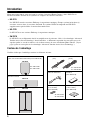
Contenu de l’emballage
Veuillez vérifier que l’emballage contient les éléments suivants.
Enceintes avant et enceintes Surround
(plus une enceinte Surround arrière pour le NS-P276)
Enceinte centrale
Subwoofer
NX-E270
X 4 <NS-P270>
X 5 <NS-P276>
NX-C270
SW-P270
Câbles d’enceintes
Câble du Subwoofer Fixations
(pour NX-C270)
Pieds antidérapants
(1 set, 8 stuks)
(pour NX-E270)
Pieds antidérapants
(1 set, 4 stuks)
(pour SW-P270)
X 2
[4 m]
X2 <NS-P270>
X3 <NS-P276>
X 2 <NS-P270>
X 3 <NS-P276>
[10 m]
X 3

3
Français
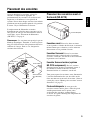
Placement des enceintes
Avant de brancher les enceintes, placez-les
chacune à l’emplacement approprié. Le
positionnement des enceintes est un facteur très
important car il influence le son général du
système. Placez donc chaque enceinte à un endroit
produisant un son de qualité optimale à la position
d’écoute. Voyez l’illustration ci-dessous.
L’emplacement du Subwoofer est moins
déterminant que celui des autres enceintes car les
sons graves ne sont pas très directionnels. Pour en
savoir plus, voyez “Placement du Subwoofer
(SW-P270)” à la page 4.
Remarque: Ces enceintes sont protégées par un
blindage magnétique. Toutefois, si vous les placez
trop près d’un téléviseur, elles pourraient altérer les
couleurs de l’image. Dans ce cas, éloignez les
enceintes du téléviseur.
Placement des enceintes avant et
Surround (NX-E270)
Enceintes avant: Placez les deux enceintes
avant à gauche et à droite du téléviseur, à environ la
même hauteur que ce dernier et en les orientant
directement vers la position d’écoute.
Enceintes Surround: Placez les enceintes
Surround gauche et droite derrière la position
d’écoute, à environ 1,8 m du sol et en les tournant
légèrement vers l’intérieur.
Enceinte Surround arrière (système
NS-P276 uniquement): Placez l’enceinte
Surround arrière derrière la position d’écoute, à
mi-chemin exactement entre les enceintes
Surround arrière et à environ 1,8 m du sol.
Vous pouvez poser les enceintes avant, Surround et
l’enceinte Surround arrière sur des tables ou les
fixer aux murs ou sur un socle d’enceinte. (Pour en
savoir plus, voyez “Montage des enceintes avant et
Surround” à la page 5.)
Pieds antidérapants: Si vous posez les
enceintes sur une surface plane, collez les pieds
antidérapants fournis sur les quatre coins
au-dessous des enceintes, comme illustré
ci-dessus. Les pieds antidérapants empêchent les
enceintes de glisser.
Avant D
Subwoofer
Téléviseur
Avant G
Surround arrière
(pour NS-P276)
Surround D
Surround G
Centrale
Pied antidérapant

4
Placement de l’enceinte centrale
(NX-C270)
Placez l’enceinte centrale précisément à mi-chemin
entre les enceintes avant, en l’orientant directement
vers la position d’écoute. Vous pouvez poser
l’enceinte centrale sur un téléviseur (à condition
qu’il soit plat), par terre à côté du téléviseur ou au
milieu en dessous de votre écran de projecteur.
Posez uniquement l’enceinte sur une surface stable.
Si vous posez l’enceinte sur le meuble téléviseur,
etc. collez les deux fixations fournies sur le
dessous de l’enceinte et le dessus du téléviseur,
comme illustré ci-dessous. L’enceinte sera alors
maintenue et ne pourra pas tomber.
Attentions:
• Ne posez pas l’enceinte centrale sur un téléviseur
dont la surface supérieure est plus petite que la base
de l’enceinte. L’enceinte risquerait alors de tomber et
de causer des blessures.
• Ne posez pas l’enceinte centrale sur un téléviseur
dont la surface supérieure est inclinée.
• Ne touchez pas la surface adhésive d’une fixation
après avoir ôté son film protecteur car cela diminue
l’adhésion.
• Nettoyez et essuyez soigneusement la surface où vous
comptez coller l’attache. Notez que l’adhésion
diminue si vous collez l’attache sur une surface sale,
graisseuse ou humide. Une fixation mal collée peut
provoquer la chute de l’enceinte centrale.
Placement du Subwoofer
(SW-P270)
Il est recommandé de le placer sur le côté extérieur
de l’enceinte avant droite ou gauche. (Voir la fig.
A.) Il est également possible de positionner les
enceintes comme indiqué à la fig. B; cependant, si
le subwoofer est placé directement contre le mur,
l’effet de basse pourra se trouver supprimé car le
son émis par l’enceinte et le son renvoyé par le mur
s’annuleront mutuellement. Pour éviter ce
problème, placer le subwoofer à angle oblique par
rapport au mur, comme indiqué sur la fig. A.
Remarque:
Les sons de très basses fréquences du subwoofer
peuvent parfois être trop faiblement perçus à partir
d’une position d’écoute en milieu de pièce. Les ondes
renvoyées par deux murs parallèles peuvent en effet
s’annuler mutuellement et supprimer les sons de basses.
Dans un tel cas, diriger le subwoofer obliquement
par rapport au mur. Il peut être également nécessaire
de modifier le parallélisme des surfaces murales en
plaçant des étagères etc. le long des murs.
Pieds antidérapants: Collez les pieds
antidérapants fournis sur les quatre coins
au-dessous du Subwoofer. Cela l’empêchera de
glisser sous l’effet des vibrations ou de petits
chocs.
Retirez
le film
protecteur.
AB
: Subwoofer
: Enceinte avant

5
Français
Montage des enceintes avant et
Surround
Vous pouvez poser les enceintes avant et les
enceintes Surround (et l’enceinte Surround arrière
pour un système NS-P276) sur une étagère ou un
rack, par terre ou les fixer aux murs ou sur un socle
d’enceinte.
Montage mural des enceintes:
1.
Fixez les vis sur un mur ou un renfort mural
résistant, comme illustré ci-dessous. (Utilisez des
vis autotaraudeuses de 3,5 ~ 4mm de diamètre
vendu dans le commerce.)
2.Fixez les enceintes en alignant les orifices à
l’arrière sur les vis ressortant du mur.
Attentions:
• Chaque enceinte avant ou Surround pèse 0,8 kg. Ne
montez pas les enceintes sur une paroi de
contreplaqué trop mince ni sur un mur en matériau
peu résistant. Les vis risqueraient alors d’être
arrachées du mur, provoquant la chute et
l’endommagement des enceintes ou des blessures.
• Ne fixez pas les enceintes au mur avec des clous, des
fixations adhésives ou toute autre méthode résultant
en un montage précaire. Avec le temps et les
vibrations, les enceintes risquent alors de tomber.
• Pour éviter de trébucher sur les câbles d’enceintes et
prévenir les accidents que cela peut causer, fixez les
câbles le long du mur.
• Fixez les enceintes au mur de sorte que personne ne
risque de les heurter de la tête.
Installation des enceintes sur des pieds
d’enceintes en vente dans le commerce:
Vous pouvez monter les enceintes avant,
d’ambiance et d’ambiance arrière sur des pieds
d’enceintes. Si vous les installez sur des pieds
vendus dans le commerce, vous devrez visser une
fixation sous les enceintes avec une vis.
Orifices
10 mm
20 mm
minimum
70 mm
70 mm
Mur/renfort
mural
Vue arrière
Remarque: Vérifiez que la
tête des vis est bien logée
dans la partie la plus étroite
des orifices.
70 mm
Insérez uniquement
des vis M4 dans les
orifices.
Fixation (AAX34790)
(option)
Vis M4
(AAX12390)
(option)
60 mm

6
Connexions
Attention: Branchez les cordons d’alimentation du Subwoofer et des autres éléments A/V au secteur
uniquement après avoir effectué toutes les autres connexions.
Exemple typique de connexions
Vers une prise de
courant
Enceinte centrale
Enceinte Surround arrière
(pour le système NS-P276)
Subwoofer
Amplificateur
Enceintes avant Enceintes Surround
Droite DroiteGauche Gauche
Remarque: Le panneau
arrière d’amplificateur
illustré ci-dessous n’est
qu’un exemple; l’aspect
varie selon
l’amplificateur utilisé.
La pagina si sta caricando...
La pagina si sta caricando...
La pagina si sta caricando...
La pagina si sta caricando...
La pagina si sta caricando...
La pagina si sta caricando...
La pagina si sta caricando...
La pagina si sta caricando...
La pagina si sta caricando...
La pagina si sta caricando...
La pagina si sta caricando...
La pagina si sta caricando...
La pagina si sta caricando...
La pagina si sta caricando...
La pagina si sta caricando...
La pagina si sta caricando...
La pagina si sta caricando...
La pagina si sta caricando...
La pagina si sta caricando...
La pagina si sta caricando...
La pagina si sta caricando...
La pagina si sta caricando...
La pagina si sta caricando...
La pagina si sta caricando...
La pagina si sta caricando...
La pagina si sta caricando...
La pagina si sta caricando...
La pagina si sta caricando...
La pagina si sta caricando...
La pagina si sta caricando...
La pagina si sta caricando...
La pagina si sta caricando...
La pagina si sta caricando...
La pagina si sta caricando...
La pagina si sta caricando...
La pagina si sta caricando...
La pagina si sta caricando...
La pagina si sta caricando...
La pagina si sta caricando...
La pagina si sta caricando...
La pagina si sta caricando...
La pagina si sta caricando...
La pagina si sta caricando...
La pagina si sta caricando...
La pagina si sta caricando...
La pagina si sta caricando...
La pagina si sta caricando...
La pagina si sta caricando...
La pagina si sta caricando...
La pagina si sta caricando...
La pagina si sta caricando...
La pagina si sta caricando...
La pagina si sta caricando...
La pagina si sta caricando...
La pagina si sta caricando...
La pagina si sta caricando...
La pagina si sta caricando...
La pagina si sta caricando...
La pagina si sta caricando...
La pagina si sta caricando...
La pagina si sta caricando...
La pagina si sta caricando...
La pagina si sta caricando...
La pagina si sta caricando...
La pagina si sta caricando...
La pagina si sta caricando...
La pagina si sta caricando...
La pagina si sta caricando...
-
 1
1
-
 2
2
-
 3
3
-
 4
4
-
 5
5
-
 6
6
-
 7
7
-
 8
8
-
 9
9
-
 10
10
-
 11
11
-
 12
12
-
 13
13
-
 14
14
-
 15
15
-
 16
16
-
 17
17
-
 18
18
-
 19
19
-
 20
20
-
 21
21
-
 22
22
-
 23
23
-
 24
24
-
 25
25
-
 26
26
-
 27
27
-
 28
28
-
 29
29
-
 30
30
-
 31
31
-
 32
32
-
 33
33
-
 34
34
-
 35
35
-
 36
36
-
 37
37
-
 38
38
-
 39
39
-
 40
40
-
 41
41
-
 42
42
-
 43
43
-
 44
44
-
 45
45
-
 46
46
-
 47
47
-
 48
48
-
 49
49
-
 50
50
-
 51
51
-
 52
52
-
 53
53
-
 54
54
-
 55
55
-
 56
56
-
 57
57
-
 58
58
-
 59
59
-
 60
60
-
 61
61
-
 62
62
-
 63
63
-
 64
64
-
 65
65
-
 66
66
-
 67
67
-
 68
68
-
 69
69
-
 70
70
-
 71
71
-
 72
72
-
 73
73
-
 74
74
-
 75
75
-
 76
76
-
 77
77
-
 78
78
-
 79
79
-
 80
80
-
 81
81
-
 82
82
-
 83
83
-
 84
84
-
 85
85
-
 86
86
-
 87
87
-
 88
88


Yamaha NS-P270 Manuale del proprietario
- Categoria
- Subwoofer
- Tipo
- Manuale del proprietario
- Questo manuale è adatto anche per
in altre lingue
- English: Yamaha NS-P270 Owner's manual
- français: Yamaha NS-P270 Le manuel du propriétaire
- español: Yamaha NS-P270 El manual del propietario
- Deutsch: Yamaha NS-P270 Bedienungsanleitung
- русский: Yamaha NS-P270 Инструкция по применению
- Nederlands: Yamaha NS-P270 de handleiding
- dansk: Yamaha NS-P270 Brugervejledning
- svenska: Yamaha NS-P270 Bruksanvisning
- Türkçe: Yamaha NS-P270 El kitabı
- suomi: Yamaha NS-P270 Omistajan opas
- română: Yamaha NS-P270 Manualul proprietarului
Documenti correlati
-
Yamaha NS-PZ20 Manuale del proprietario
-
-
-
-
-
-
-
-
Yamaha NS-P440 Manuale del proprietario
-
Yamaha NS-P51 Black Manuale utente
Altri documenti
-
Pioneer S-C73A Manuale utente
-
Sony SA-WX900 Manuale del proprietario
-
Sony SA-WX700 Manuale del proprietario
-
Kenwood KS-708HT Manuale utente
-
Sony SA-W3000 Manuale del proprietario
-
NAD C270 Manuale utente
-
Pioneer HTP-SLH500 Manuale del proprietario
-
Sony HT-SL5 Manuale del proprietario
-
Sony WAHT-SA1 Manuale del proprietario
-
Pioneer HTP-SL050 Manuale del proprietario