dBTechnologies GSA-IGA Manuale del proprietario
- Tipo
- Manuale del proprietario

FOT000088 REV.1.0
GSA-IGA
ISTRUZIONI DI UTILIZZO GSA-IGA
GSA-IGA INSTRUCTIONS
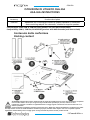
Contenuto della confezione
Packing content
ATTENZIONE: GSA-IGA deve essere utilizzato solo da personale qualicato! Assicurarsi che l’installazione sia posizio-
nata in modo stabile e sicuro per scongiurare ogni condizione di pericolo per persone, animali e/o cose.
L’utilizzatore è tenuto a vericare le regolamentazioni e le leggi cogenti in materia di sicurezza nel Paese in cui si
utilizza il prodotto.
Accessorio
Accessory
Descrizione del Prodotto
Product description
GSA-IGA Adattatore per il montaggio stacked di speaker INGENIA su subwoofer
Stack-mounting adapter on subwoofer, suitable for Ingenia speakers
Compatibilità: SERIE SUB H, SUB 600, DVA (modelli con foro pole-mount M20)
Compatibility: SUB H, SUB 600, DVA SERIES (product with M20 threaded pole-mount hole)
WARNING: GSA-IGA must be installed by experienced personnel only! Make sure that the installation is positioned in a stable
and safe manner in order to avoid hazardous conditions for people, animals and/or objects. The user is required to follow
regulations and mandatory laws on safety of the country in which the product is used. product is used.

GSA-IGA
FOT000088 REV.1.0
Istruzioni di utilizzo
Instructions for use
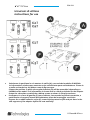
1 Selezionare la posizione in cui montare le staffe (A), a seconda del modello di INGENIA.
Le informazioni relative sono mostrate anche sull’etichetta posta sull’adattatore. Fissare le
2 staffe avvitando le 4 viti M6x12 come da gura sopra.
Choose the position in which the angular brackets (A) will be assembled, depending on
INGENIA series model. This information is shown also in a label positioned on the adapter.
Fasten the 2 brackets screwing the 4 M6x14 screws as shown in the picture above.
2 Predisporre le 2 fasce di gomma (F) come indicato, rimuovendo la pellicola protettiva, e
posizionarle sui supporti laterali dell’adattatore prima del montaggio successivo.
Prepare the 2 rubber adhesive strips (F), removing the protective lm and put them in the
side supports of the adapter before the next assembly.

FOT000088 REV.1.0
GSA-IGA
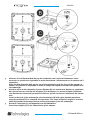
3 Allineare il foro lettato M20 del top del subwoofer con l’asola dell’adattatore come
mostrato. La posizione è regolabile in modo da adattare l’allineamento tra lo speaker ed il
subwoofer.
Align the M20 threaded hole on the top of the subwoofer with the loop of the adapter as
shown. The position is adjustable in order to adapt the aligment between the speaker and
the subwoofer.
4 Avvitare nel foro del subwoofer il perno lettato (B) con movimento destrorso, completan-
do l’operazione con l’ausilio del minipalo (C) in dotazione. Lo stesso minipalo (utilizzato
con movimento sinistrorso) permette di svitare e quindi rimuovere l’adattatore dal subwo-
ofer.
Screw in the hole of the wubwoofer the threaded pin (B) with right-handed movement,
using the minipole (C) to complete this operation. The same minipole is useful to unscrew
(with left-handed movement) and to remove the adapter from the subwoofer.
5 Avvitare il minipalo (C) nell’apposito foro dell’adattatore.
Screw the minipole (C) in the related hole of the adapter.

GSA-IGA
FOT000088 REV.1.0
A.E.B. Industriale Srl V ia Brodolini, 8 Località Crespellano 40053 VALSAMOGGIA BOLOGNA (ITALIA)
Tel +39 051 969870 Fax +39 051 969725 www.dbtechnologies.com info@dbtechnologies-aeb.com
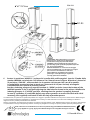
ATTENZIONE: Al ne dell’utilizzo in sicurezza
dell’accessorio, vericarne periodicamente
funzionalità e integrità prima dell’utilizzo.
WARNING: Check periodically the integrity and
functionality of this optional equipment before the
use, for a safe installation.
6 Portare in posizione “APERTO” i 4 pistoncini a molla delle staffe angolari. Inserire il fondo dello
speaker INGENIA nel minipalo C ed allineare i fori laterali come in gura. Rilasciare i pistoncini
in posizione “CHIUSO”, assicurandosi che lo speaker sia bloccato. Nel caso di 2 speaker,
è consigliabile preparare prima lo stack con l’accessorio LP-IG (non incluso) ed eseguire
l’installazione con l’ausilio di un’altra persona.
Put the 4 indexing plungers of angular brackets in “OPEN” position. Insert the bottom of the
INGENIA speaker in the C minipole aligning the side holes as shown in the picture. Release the
indexing plungers in “CLOSED” position, checking that the speaker is properly fastened.
In case of 2 speakers it is advisible before any other operation to mount the stack with LP-IG
accessory (not supplied) and install it with the help of another person.
Features, specication and appearance of products are subject to change without notice. dBTechnologies reserves the right to make changes
or improvements in design or mafacturing without assuming any obligation to change or improve products previously manufactured.
Le caratteristiche, le speciche e l’aspetto dei prodotti sono soggetti a possibili cambiamenti senza previa comunicazione. dBTechnologies
si riserva il diritto di apportare cambiamenti o miglioramenti nel design o nelle lavorazioni senza assumersi l’obbligo di cambiare o
migliorare anche i prodotti precedentemente realizzati.
NOTA DI SICUREZZA: E’ necessario un ssaggio
meccanico addizionale o un ssaggio con cinghie
per assicurare l’installazione in sicurezza.
SAFETY NOTICE: an additional mechanical
fastening or a belt fastening is required to
correctly fasten the installation.
LP-IG
-
 1
1
-
 2
2
-
 3
3
-
 4
4


dBTechnologies GSA-IGA Manuale del proprietario
- Tipo
- Manuale del proprietario
in altre lingue
Documenti correlati
-
dBTechnologies GSA-IG Manuale del proprietario
-
-
-
-
-
-
INGENIA IG3T Manuale utente
-
dB Technologies DRK-IG Manuale utente
-
-