dBTechnologies GSA-IG Manuale del proprietario
- Tipo
- Manuale del proprietario

GSA-IG Adapter
ISTRUZIONI DI UTILIZZO GSA-IG
GSA-IG INSTRUCTIONS
GSA-IG --> Adattatore per appoggio su subwoofer /
a terra per la serie INGENIA.
Modelli di subwoofer compatibili: DVA S09 DP, DVA S10 DP, DVA S1521 N, DVA S1518 N, DVA
S2585 N, SUB 15H, SUB 18H.
GSA-IG --> Subwoofer mounting / ground adapter for INGENIA series speaker.
Compatible Subwoofers: DVA S09 DP, DVA S10 DP, DVA S1521 N, DVA S1518 N, DVA S2585 N,
SUB 15H, SUB 18H.
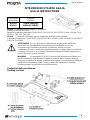
ATTENZIONE GSA-IG deve essere utilizzato solo da personale qualificato!
Assicurarsi che l’installazione sia posizionata in modo stabile e sicuro per
scongiurare ogni condizione di pericolo per persone, animali e/o cose.
L’utilizzatore è tenuto a verificare le regolamentazioni e le leggi cogenti in materia di
sicurezza nel Paese in cui si utilizza il prodotto. Installare il prodotto attenendosi a
quanto illustrato in queste istruzioni.
WARNING For installation of GSA-IG use only specialist personnel! Make sure
that the installation is positioned in a stable and secure way in order to avoid any
dangerous conditions for people, animals and/or objects. It is mandatory to follow the
safety law and regulations of the Country in which the equipment is installed.
Install the product as described in these instructions.
Contenuto della confezione
Packing content
Accessorio
Accessory
Prodotto
Product
GSA-IG
GSA-IG
SERIE INGENIA
INGENIA SERIES

GSA-IG Adapter
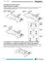
Montaggio delle staffe angolari
Angular brackets assembly
Avvitare le staffe con le 4 viti M6X12 nella posizione mostrata sotto, in base al modello di Ingenia.
Screw the 4 M6X12 screws, to mount the 2 angular brackets in the position shown below,
according with the speaker model.
1) Installazione su subwoofer (esempio con Ingenia IG4T e Sub 18H)
1) Installation on a subwoofer (Ingenia IG4T and Sub 18H example)
a) Dopo aver staccato la pellicola protettiva, apporre le strisce adesive di gomma sul lato inferiore
di GSA-IG per prevenire le vibrazioni, in una posizione che non occluda nessun foro.
a) After removing the protective film, put the adhesive rubber strips as shown on the lower side of
GSA-IG to prevent vibrations, in a position in which all the holes are clear.

GSA-IG Adapter
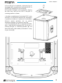
b) Porre GSA-IG sul subwoofer, centrando il foro di
montaggio M20 e posizionare il mini-palo DS2-S in
posizione di avvitamento come mostrato.
b) Put GSA-IG adapter on the subwoofer, aligning
the M20 hole, and put the DS2-S mini-pole in
screwing position as shown.
c) Avvitare completamente il mini-palo DS2-S come
mostrato, con movimento destrorso [1]. Allontanare
in posizione di sblocco i 4 pistoncini a molla [2], e
bloccare questa posizione con un piccolo
movimento rotatorio in uno dei due sensi [3].
c) Screw completely the DS2-S mini-pole as shown
with a right-handed movement [1]. Pull all the 4
indexing plungers in unblocking position [2], and
block them with a little rotatory movement in a way
of your choice [3].

GSA-IG Adapter
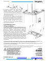
d) Inserire lo speaker IG4T nella sede di
fissaggio allineando i fori inferiori come
mostrato e rilasciare tutti e 4 i pistoncini tramite
un piccolo movimento rotatorio. Verificare che
i pistoncini siano correttamente inseriti e fissati
nelle sedi dello speaker.
d) Insert the IG4T speaker in the mounting
position, aligning the lower holes of the speaker
as shown and release all the 4 indexing
plungers with a little rotatory movement. Check
that the indexing plungers are inserted
correctly in the holes of the speaker and that
they are properly fastened.
2) Installazione a terra
2) Floor installation
a) Dopo aver staccato la pellicola protettiva, apporre le
strisce adesive di gomma sul lato inferiore di GSA-IG per
prevenire le vibrazioni, in una posizione che non occluda
nessun foro. Utilizzare i 4 fori mostrati in figura, per
ancorare a terra GSA-IG con opportuni mezzi di fissaggio
meccanico (non inclusi). Tali mezzi devono essere
compatibili con il tipo di pavimentazione presente.
a) After removing the protective film, put the adhesive
rubber strips as shown on the lower side of GSA-IG to
prevent vibrations, in a position in which all the holes are
clear. Use the 4 holes, as shown in picture, to secure GSA-
IG to the floor, with mechanical fastening system, not
included. The mechanical system must be suitable for the
floor material.
b) Seguire le istruzioni di montaggio 1-c) e 1-d), come nell’esempio di montaggio su subwoofer, ma
senza utilizzare il palo DS2-S, che non deve essere montato in questa applicazione.
b) Follow the 1-c) and 1-d) instructions, like in subwoofer mounting example, but do not use DS2-S
mini-pole in this kind of installation.
Features, specification and appearance of products are subject to change without notice.
dBTechnologies reserves the right to make changes or improvements in design or manufacturing without
assuming any obligation to change or improve products previously manufactured.
A.E.B. Industriale Srl
Via Brodolini, 8
Località Crespellano
40053 VALSAMOGGIA
BOLOGNA (ITALIA)
Tel +39 051 969870
Fax +39 051 969725
FOT000074 REV.1.0 www.dbtechnologies.com info@dbtechnologies-aeb.com
-
 1
1
-
 2
2
-
 3
3
-
 4
4


dBTechnologies GSA-IG Manuale del proprietario
- Tipo
- Manuale del proprietario
in altre lingue
- English: dBTechnologies GSA-IG Owner's manual
Documenti correlati
-
dBTechnologies GSA-IGA Manuale del proprietario
-
-
-
dB Technologies DRK-IG Manuale utente
-
INGENIA IG3T Manuale utente
-
-
-
-
-