
AMP100
Connection Box
Installation and Operating Manual . . . . . . 6
Anschlussbox
Montage- und Bedienungsanleitung . . . 15
Boîte de commande
Instructions de montage
et de service . . . . . . . . . . . . . . . . . . . . . . . 24
Caja de distribución
Instrucciones de montaje y de uso . . . . .33
Caixa de conexão
Instruções de montagem e manual de
instruções . . . . . . . . . . . . . . . . . . . . . . . . . 42
Scatola di comando
Istruzioni di montaggio e d’uso . . . . . . . . 51
Schakelbox
Montagehandleiding en
gebruiksaanwijzing. . . . . . . . . . . . . . . . . . 60
Kontrolboks
Monterings- og betjeningsvejledning. . . 69
Kopplingsbox
Monterings- och bruksanvisning. . . . . . . 78
Koblingsboks
Monterings- og bruksanvisning . . . . . . . 87
Kytkinrasia
Asennus- ja käyttöohje. . . . . . . . . . . . . . . 96
Клеммная коробка
Инструкция по монтажу
и эксплуатации. . . . . . . . . . . . . . . . . . . . 105
Skrzynka przyłączeniowa
Instrukcja montażu i obsługi . . . . . . . . . .114
Prípojný box
Návod na montáž a uvedenie
do prevádzky . . . . . . . . . . . . . . . . . . . . . 123
Rozvodná skříňka
Návod k montáži a obsluze . . . . . . . . . . 132
Csatlakozódoboz
Szerelési és használati útmutató . . . . . . .141
EN
DE
FR
ES
PT
IT
NL
DA
SV
NO
FI
RU
PL
SK
CS
HU
DRIVING SUPPORT
PERFECTVIEW
AMP100-IO-16s.book Seite 1 Mittwoch, 26. Oktober 2016 11:15 11

AMP100-IO-16s.book Seite 2 Mittwoch, 26. Oktober 2016 11:15 11

AMP100
3
1
4
8
11 12 13
910
56 7
23
1
AMP100-IO-16s.book Seite 3 Mittwoch, 26. Oktober 2016 11:15 11

AMP100
4
2
3
1
2
4
AMP100-IO-16s.book Seite 4 Mittwoch, 26. Oktober 2016 11:15 11

AMP100
5
12
3
4
5
6
7
8
9
5
AMP100-IO-16s.book Seite 5 Mittwoch, 26. Oktober 2016 11:15 11

Explanation of symbols AMP100
EN
6
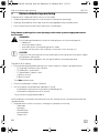
Please read this instruction manual carefully before installation and first use, and store
it in a safe place. If you pass on the product to another person, hand over this instruc-
tion manual along with it.
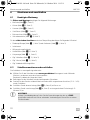
Table of contents
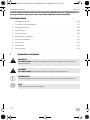
1 Explanation of symbols. . . . . . . . . . . . . . . . . . . . . . . . . . . . . . . . . . . . . . . . . . . . . . . . . . . . . . . 6
2 Safety and installation instructions . . . . . . . . . . . . . . . . . . . . . . . . . . . . . . . . . . . . . . . . . . . . . .7
3 Scope of delivery . . . . . . . . . . . . . . . . . . . . . . . . . . . . . . . . . . . . . . . . . . . . . . . . . . . . . . . . . . . 9
4 Intended use . . . . . . . . . . . . . . . . . . . . . . . . . . . . . . . . . . . . . . . . . . . . . . . . . . . . . . . . . . . . . . . 9
5 Technical description . . . . . . . . . . . . . . . . . . . . . . . . . . . . . . . . . . . . . . . . . . . . . . . . . . . . . . . . 9
6 Installation and connection . . . . . . . . . . . . . . . . . . . . . . . . . . . . . . . . . . . . . . . . . . . . . . . . . . 11
7 Setting the control box. . . . . . . . . . . . . . . . . . . . . . . . . . . . . . . . . . . . . . . . . . . . . . . . . . . . . . 13
8 Warranty . . . . . . . . . . . . . . . . . . . . . . . . . . . . . . . . . . . . . . . . . . . . . . . . . . . . . . . . . . . . . . . . . 13
9 Disposal. . . . . . . . . . . . . . . . . . . . . . . . . . . . . . . . . . . . . . . . . . . . . . . . . . . . . . . . . . . . . . . . . . 14
10 Technical data. . . . . . . . . . . . . . . . . . . . . . . . . . . . . . . . . . . . . . . . . . . . . . . . . . . . . . . . . . . . . 14
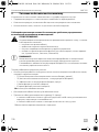
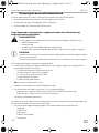
1 Explanation of symbols
!
!
A
I
WARNING!
Safety instruction: Failure to observe this instruction can cause fatal or serious injury.
CAUTION!
Safety instruction: Failure to observe this instruction can lead to injury.
NOTICE!
Failure to observe this instruction can cause material damage and impair the function
of the product.
NOTE
Supplementary information for operating the product.
AMP100-IO-16s.book Seite 6 Mittwoch, 26. Oktober 2016 11:15 11

AMP100 Safety and installation instructions
EN
7
2 Safety and installation instructions
The manufacturer accepts no liability for damage in the following cases:
• Damage to the product resulting from mechanical influences and excess voltage
• Alterations to the product without express permission from the manufacturer
• Use for purposes other than those described in the operating manual
Please observe the prescribed safety instructions and stipulations from the vehicle
manufacturer and service workshops.
!
WARNING!
Inadequate supply cable connections could result in short circuits, which could have as
a consequence that:
• Cable fires occur
• The airbag is triggered
• Electronic control devices are damaged
• Electric functions fail (indicators, brake light, horn, ignition, lights)
A
NOTICE!
To prevent the risk of short circuits, always disconnect the negative terminal of the
vehicle's electrical system before working on it.
If the vehicle has an additional battery, its negative terminal should also be discon-
nected.
Please observe the following instructions:
• When working on the following cables, only use insulated cable lugs, plugs and flat push-on
receptacles:
– 30 (direct supply from positive battery terminal)
–15 (connected positive terminal, behind the battery)
– 31 (return line from the battery, earth)
– L (indicator lights left)
– R (indicator lights right)
Do not use terminal strips.
• Use a crimping tool to connect the cables.
• When connecting to cable 31 (earth), screw the cable
– to the vehicle's earth bolt with a cable lug and a gear disc or
– to the sheet-metal bodywork with a cable lug and a self-tapping screw.
Ensure that there is a good earth connection.
AMP100-IO-16s.book Seite 7 Mittwoch, 26. Oktober 2016 11:15 11

Safety and installation instructions AMP100
EN
8
If you disconnect the negative terminal of the battery, all data stored in the volatile memories will
be lost.
• The following data must be set again, depending on the vehicle equipment options:
–Radio code
– Vehicle clock
–Timer
– On-board computer
– Seat position
You can find instructions for making these settings in the appropriate operating instructions.
Observe the following installation instructions:
!
CAUTION!
• Secure the parts installed in the vehicle in such a way that they cannot become loose
under any circumstances (sudden braking, accidents) and cause injuries to the
occupants of the vehicle.
• Secure any parts of the system covered by the bodywork in such a manner that they
cannot be come loose or damage other parts and cables or impair vehicle functions
(steering, pedals, etc).
• Always follow the safety instructions of the vehicle manufacturer.
Some work (e.g. on retention systems such as the AIRBAG etc.) may only be
performed by qualified specialists.
A
NOTICE!
• To prevent damage when drilling, make sure there is sufficient space on the other
side for the drill head to come out.
• Deburr all drill holes and treat them with a rust-protection agent.
Observe the following instructions when working with electrical parts:
A
NOTICE!
• When testing the voltage in electrical cables, only use a diode test lamp or a
voltmeter.
Test lamps with an illuminant take up voltages which are too high and which can
damage the vehicle's electronic system.
• When making electrical connections, ensure that:
– they are not kinked or twisted
– they do not rub on edges
– they are not laid in sharp edged ducts without protection.
• Insulate all connections.
• Secure the cables against mechanical wear with cable binders or insulating tape,
for example to existing cables.
AMP100-IO-16s.book Seite 8 Mittwoch, 26. Oktober 2016 11:15 11

AMP100 Scope of delivery
EN
9
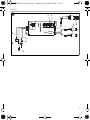
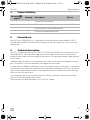
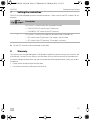
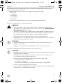
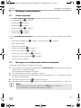
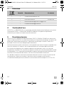
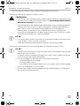
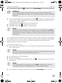
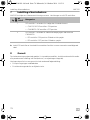
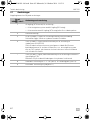
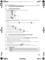
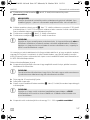
3Scope of delivery
4Intended use
AMP100 (ref. no. 9600000210) is a control box for connecting the camera models CAM33,
CAM44 and CAM80CM with motor-driven protective flaps to a monitor for use as a reversing
video system.
5 Technical description
AMP100 is used to connect cameras CAM33, CAM44 and CAM80CM to a monitor with cinch
video input (RCA). The control box supplies the control signal for the camera’s motor-driven
protective cover and the activation signal for the monitor. It also provides a proper supply of power
to the camera.
In default mode, the camera is activated when you switch on the monitor or engage the reverse
gear. The monitor is also activated when you engage the reverse gear.
If a video source in addition to the camera, such as a navigation system or DVD player, is connected
to the monitor, you need to set and connect the control box accordingly. In that case, the control
signal for the camera protective cover is not triggered when you switch on the monitor but only
when you shift into reverse gear.
If you would then like to use the camera when the vehicle is parked or when driving forwards,
you must install the supplied rocker switch.
The control box can be connected to 12 V to 24 V DC voltage.
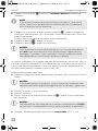
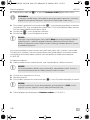
No. in fig. 4,
page 4
Quantity Description Ref. no.
1 1 Control box with cable set
2 1 Rocker switch RV-AMP-SW
– 1 Installation material with cable fasteners
– 1 Installation and operating manual
AMP100-IO-16s.book Seite 9 Mittwoch, 26. Oktober 2016 11:15 11

Technical description AMP100
EN
10
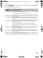
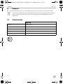
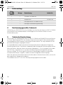
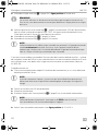
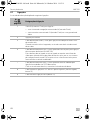
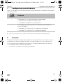
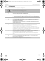
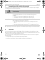
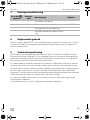
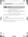
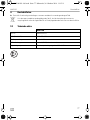
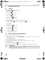
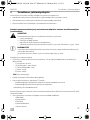
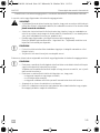
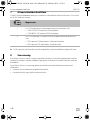
5.1 Connections
The control box has the following connections:
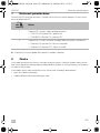
No. in
fig. 5, page 5
Connection description
3 AV output (cinch plug) for connecting...
• to a navigation system with an AV input (cinch socket)
• to another monitor with an AV input (cinch socket) or to a video recorder
4Camera connection
5 Green control cable (+ signal) for connecting the positive cable of the
reversing light
When you shift into reverse gear, the control box is activated via this cable.
6 Black control line (+ signal) with flat plug fitting for connection of the
RV-AMP-SW rocker switch.
This line must be connected when a video source in addition to the
reversing video camera – such as a navigation system or DVD player – is
connected to the monitor and you would like to activate the camera when
parked or driving forwards.
7 Black control line (+ signal) with round plug lug for connection to the
monitor’s S/BY signal input.
The monitor is switched on via this line when the control box is activated.
8 Red cable: connection to 12 V to 24 V positive (e.g. connected positive
terminal, terminal 15)
9 Brown cable: connection to earth (terminal 31)
AMP100-IO-16s.book Seite 10 Mittwoch, 26. Oktober 2016 11:15 11

AMP100 Installation and connection
EN
11
6 Installation and connection
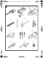
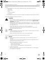
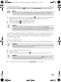
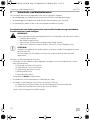
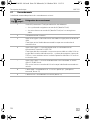
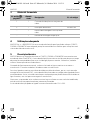
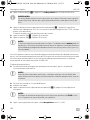
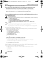
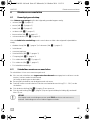
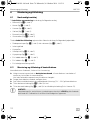
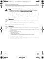
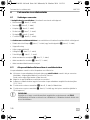
6.1 Tools required
For installation and assembly, you will need the following tools:
• Measuring ruler (fig. 1 4, page 3)
• Centre punch (fig. 1 5, page 3)
• Hammer (fig. 1 6, page 3)
• Drill bit set (fig. 1 7, page 3)
• Electric drill (fig. 1 8, page 3)
• Screwdriver (fig. 1 9, page 3)
To establish and test the electrical connection, the following tools are required:
• Diode test lamp (fig. 1 1, page 3) or voltmeter (fig. 1 2, page 3)
• Insulating tape
• Heat shrinking sleeve
• Hot air blower (fig. 1 10, page 3)
• Crimping tool (fig. 1 11, page 3)
• Soldering iron (optional) (fig. 1 12, page 3)
• Solder (optional) (fig. 1 13, page 3)
• Cable bushing sleeves (optional)
6.2 Installing and connecting the control box
The control box is supplied ready for installation.
➤ Install the control box in a location protected from water near the monitor, preferably under
the dashboard.
Make sure you consider the length of the cable.
➤ Attach the control box using the supplied screws.
➤ Insert the plug and the cable set in the connection provided (12 – 24 V) on the control box.
➤ Connect the black cable (fig. 5 9, page 5) to earth.
➤ Connect the red cable (fig. 5 8, page 5) to an active positive cable (such as terminal 15).
A
NOTICE!
Ensure that you connect the control cables correctly to + PLUS and not to earth.
Connecting the control cables to earth can damage the device.
AMP100-IO-16s.book Seite 11 Mittwoch, 26. Oktober 2016 11:15 11

Installation and connection AMP100
EN
12
➤ Connect the green cable (fig. 5 5, page 5) to the positive cable of the reversing light.
I
➤ Connect the black cable with the round plug lug (fig. 5 7, page 5) to the monitor connection
labelled S/BY or to the violet-white cable of NAV-7300 navigation system monitor.
The monitor receives its activation signal via this cable.
➤ Connect the plug (fig. 5 3, page 5) to the monitor.
➤ Connect the plug (fig. 5 4, page 5) to the camera.
A
If a video source in addition to the reversing video camera – such as a navigation system or DVD
player – is connected to the monitor and you would like to activate the camera when parked or
moving fowards, you need to connect the black control cable with the flat plug lug to the
RV-AMP-SW rocker switch.
To do this, proceed as follows:
➤ Select a suitable installation location for the switch, such as on the dashboard near the monitor.
A
➤ Drill a hole approximately 20 mm in diameter.
➤ Mount the switch.
➤ Plug the black cable with flat plug lug (fig. 5 6, page 5) into a connection on the switch.
A
➤ Connect the other switch connection to a positive line with 12 V to 24 V.
NOTE
On some vehicles, the reversing light only works when the ignition is switched on. In
this case, you must switch on the ignition to identify the positive and earth cables.
NOTICE!
Ensure that all cables are connected correctly. The control line may never be
connected to earth; doing so can damage the device. Make especially sure to insulate
the bare end of the control line when it is not in use and thus not connected.
NOTICE!
Before drilling any holes, ensure that no electrical cables or other parts of the vehicle
can be damaged by drilling, sawing and filing.
NOTICE!
Ensure that you connect the other connection correctly to + PLUS and not to earth.
Connecting the control cables to earth can damage the device.
AMP100-IO-16s.book Seite 12 Mittwoch, 26. Oktober 2016 11:15 11

AMP100 Setting the control box
EN
13
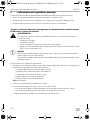
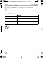
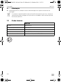
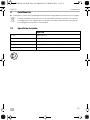
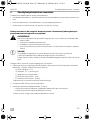
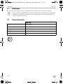
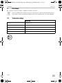
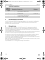
7 Setting the control box
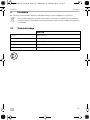
AMP100 must be adapted to certain connection options. There are two small DIP switches for this
purpose.
➤ Set the DIP switches as desired based on the table.
8Warranty
The statutory warranty period applies. If the product is defective, please contact your retailer or the
manufacturer's branch in your country (see the back of the instruction manual for the addresses).
For repair and guarantee processing, please include the following documents when you send in
the device:
• A copy of the receipt with purchasing date
• A reason for the claim or description of the fault
No. in
fig. 5, page 5
Description
1 DIP switch 1 is used to select the connected camera:
• CAM33/44: DIP switch in the ON position
• CAM80CM: DIP switch in the OFF position
2 DIP switch 2 is used to set image mirroring on camera CAM80CM:
• DIP switch in the ON position: The image is not mirrored.
• DIP switch in the OFF position: The image is mirrored.
AMP100-IO-16s.book Seite 13 Mittwoch, 26. Oktober 2016 11:15 11

Disposal AMP100
EN
14
9Disposal
➤ Place the packaging material in the appropriate recycling waste bins wherever possible.
M
If you wish to finally dispose of the product, ask your local recycling centre or specialist
dealer for details about how to do this in accordance with the applicable disposal
regulations.
10 Technical data
AMP100
Ref. no.: 9600000210
Dimensions (W x H x D): 117 x 50 x 25 mm
Operating voltage: 12 V – 24 Vg
Power consumption: Max. 0.5 W (without camera)
Control inputs: Positive 12 V – 24 V power signals
4
AMP100-IO-16s.book Seite 14 Mittwoch, 26. Oktober 2016 11:15 11

AMP100 Erklärung der Symbole
DE
15
Bitte lesen Sie diese Anleitung vor Einbau und Inbetriebnahme sorgfältig durch und
bewahren Sie sie auf. Geben Sie sie im Falle einer Weitergabe des Produktes an den
Nutzer weiter.
Inhaltsverzeichnis
1 Erklärung der Symbole. . . . . . . . . . . . . . . . . . . . . . . . . . . . . . . . . . . . . . . . . . . . . . . . . . . . . . 15
2 Sicherheits- und Einbauhinweise. . . . . . . . . . . . . . . . . . . . . . . . . . . . . . . . . . . . . . . . . . . . . . 16
3 Lieferumfang . . . . . . . . . . . . . . . . . . . . . . . . . . . . . . . . . . . . . . . . . . . . . . . . . . . . . . . . . . . . . . 18
4 Bestimmungsgemäßer Gebrauch . . . . . . . . . . . . . . . . . . . . . . . . . . . . . . . . . . . . . . . . . . . . . 18
5 Technische Beschreibung . . . . . . . . . . . . . . . . . . . . . . . . . . . . . . . . . . . . . . . . . . . . . . . . . . . 18
6 Montieren und anschließen . . . . . . . . . . . . . . . . . . . . . . . . . . . . . . . . . . . . . . . . . . . . . . . . . .20
7 Schaltbox einstellen . . . . . . . . . . . . . . . . . . . . . . . . . . . . . . . . . . . . . . . . . . . . . . . . . . . . . . . .22
8 Gewährleistung . . . . . . . . . . . . . . . . . . . . . . . . . . . . . . . . . . . . . . . . . . . . . . . . . . . . . . . . . . .22
9 Entsorgung . . . . . . . . . . . . . . . . . . . . . . . . . . . . . . . . . . . . . . . . . . . . . . . . . . . . . . . . . . . . . . .23
10 Technische Daten . . . . . . . . . . . . . . . . . . . . . . . . . . . . . . . . . . . . . . . . . . . . . . . . . . . . . . . . . .23
1 Erklärung der Symbole
!
!
A
I
WARNUNG!
Sicherheitshinweis: Nichtbeachtung kann zu Tod oder schwerer Verletzung führen.
VORSICHT!
Sicherheitshinweis: Nichtbeachtung kann zu Verletzungen führen.
ACHTUNG!
Nichtbeachtung kann zu Materialschäden führen und die Funktion des Produktes
beeinträchtigen.
HINWEIS
Ergänzende Informationen zur Bedienung des Produktes.
AMP100-IO-16s.book Seite 15 Mittwoch, 26. Oktober 2016 11:15 11

Sicherheits- und Einbauhinweise AMP100
DE
16
2 Sicherheits- und Einbauhinweise
Der Hersteller übernimmt in folgenden Fällen keine Haftung für Schäden:
• Beschädigungen am Produkt durch mechanische Einflüsse und Überspannungen
• Veränderungen am Produkt ohne ausdrückliche Genehmigung vom Hersteller
• Verwendung für andere als die in der Anleitung beschriebenen Zwecke
Beachten Sie die vom Fahrzeughersteller und vom Kfz-Handwerk vorgeschriebenen
Sicherheitshinweise und Auflagen!
!
WARNUNG!
Unzureichende Leitungsverbindungen können zur Folge haben, dass durch Kurzschluss
• Kabelbrände entstehen,
• der Airbag ausgelöst wird,
• elektronische Steuerungseinrichtungen beschädigt werden,
• elektrische Funktionen ausfallen (Blinker, Bremslicht, Hupe, Zündung, Licht).
A
ACHTUNG!
Klemmen Sie wegen der Kurzschlussgefahr vor Arbeiten an der Fahrzeugelektrik immer
den Minuspol ab.
Bei Fahrzeugen mit Zusatzbatterie müssen Sie an dieser ebenfalls den Minuspol
abklemmen.
Beachten Sie deshalb folgende Hinweise:
• Verwenden Sie bei Arbeiten an den folgenden Leitungen nur isolierte Kabelschuhe, Stecker
und Flachsteckhülsen:
– 30 (Eingang von Batterie Plus direkt)
– 15 (Geschaltetes Plus, hinter Batterie)
– 31 (Rückleitung ab Batterie, Masse)
– L (Blinkerleuchten links)
– R (Blinkerleuchten rechts)
Verwenden Sie keine Lüsterklemmen.
• Verwenden Sie eine Krimpzange zum Verbinden der Kabel.
• Schrauben Sie das Kabel bei Anschlüssen an Leitung 31 (Masse)
– mit Kabelschuh und Zahnscheibe an eine fahrzeugeigene Masseschraube oder
– mit Kabelschuh und Blechschraube an das Karosserieblech.
Achten Sie auf eine gute Masseübertragung!
AMP100-IO-16s.book Seite 16 Mittwoch, 26. Oktober 2016 11:15 11

AMP100 Sicherheits- und Einbauhinweise
DE
17
Beim Abklemmen des Minuspols der Batterie verlieren alle flüchtigen Speicher der Komfort-
elektronik ihre gespeicherten Daten.
• Folgende Daten müssen Sie je nach Fahrzeugausstattung neu einstellen:
–Radiocode
–Fahrzeuguhr
– Zeitschaltuhr
– Bordcomputer
– Sitzposition
Hinweise zur Einstellung finden Sie in der jeweiligen Bedienungsanleitung.
Beachten Sie folgende Hinweise bei der Montage:
!
VORSICHT!
• Befestigen Sie die im Fahrzeug montierten Teile so, dass sie sich unter keinen
Umständen (scharfes Abbremsen, Verkehrsunfall) lösen und zu Verletzungen der
Fahrzeuginsassen führen können.
• Befestigen Sie verdeckt unter Verkleidungen anzubringende Teile des Systems so,
dass sie sich nicht lösen oder andere Teile und Leitungen beschädigen und keine
Fahrzeugfunktionen (Lenkung, Pedale usw.) beeinträchtigen können.
• Beachten Sie immer die Sicherheitshinweise des Fahrzeugherstellers.
Einige Arbeiten (z. B. an Rückhaltesystemen wie Airbag usw.) dürfen nur von geschul-
tem Fachpersonal durchgeführt werden.
A
ACHTUNG!
• Achten Sie beim Bohren auf ausreichenden Freiraum für den Bohreraustritt, um
Schäden zu vermeiden.
• Entgraten Sie jede Bohrung und behandeln Sie diese mit Rostschutzmittel.
Beachten Sie folgende Hinweise bei der Arbeit an elektrischen Teilen:
A
ACHTUNG!
• Benutzen Sie zum Prüfen der Spannung in elektrischen Leitungen nur eine Dioden-
prüflampe oder ein Voltmeter.
Prüflampen mit einem Leuchtkörper nehmen zu hohe Ströme auf, wodurch die
Fahrzeugelektronik beschädigt werden kann.
• Beachten Sie beim Verlegen der elektrischen Anschlüsse, dass diese
– nicht geknickt oder verdreht werden,
– nicht an Kanten scheuern,
– nicht ohne Schutz durch scharfkantige Durchführungen verlegt werden.
• Isolieren Sie alle Verbindungen und Anschlüsse.
• Sichern Sie die Kabel gegen mechanische Beanspruchung durch Kabelbinder oder
Isolierband, z. B. an vorhandenen Leitungen.
AMP100-IO-16s.book Seite 17 Mittwoch, 26. Oktober 2016 11:15 11

Lieferumfang AMP100
DE
18
3Lieferumfang
4 Bestimmungsgemäßer Gebrauch
AMP100 (Art.-Nr. 9600000210) ist eine Schaltbox zum Anschluss der Kameras CAM33, CAM44
und CAM80CM mit motorbetriebener Schutzklappe an einen Monitor für den Einsatz als
Rückfahrvideosystem.
5 Technische Beschreibung
AMP100 dient zur Anbindung der Kameras CAM33, CAM44 und CAM80CM an einen Monitor
mit Cinch-Video-Eingang (RCA). Die Schaltbox liefert das Steuersignal für die motorbetriebene
Schutzklappe der Kamera und das Einschaltsignal für den Monitor. Sie sorgt außerdem für eine
passende Spannungsversorgung der Kamera.
Im Standardbetrieb wird die Kamera beim Einschalten des Monitors oder beim Einlegen des
Rückwärtsgangs aktiviert. Der Monitor wird ebenfalls beim Einlegen des Rückwärtsgangs aktiviert.
Wenn am Monitor außer der Kamera eine weitere Videoquelle, z. B. ein Navigationssystem oder
ein DVD-Player, angeschlossen ist, muss die Schaltbox entsprechend eingestellt und ange-
schlossen werden. Das Steuersignal für die Kamera-Schutzklappe wird dann nicht durch das
Einschalten des Monitors ausgelöst, sondern nur beim Einlegen des Rückwärtsgangs.
Wenn Sie in diesem Fall die Kamera bei Vorwärtsfahrt oder im Stand aktivieren wollen, müssen Sie
den mitgelieferten Wippschalter einbauen.
Die Schaltbox kann an 12-V- bis 24-V-Gleichspannung angeschlossen werden.
Nr. in
Abb. 4,
Seite 4
Menge Bezeichnung Artikel-Nr.
1 1 Schaltbox mit Kabelsatz
2 1 Wippschalter RV-AMP-SW
– 1 Montagematerial mit Kabelfixierung
– 1 Montage- und Bedienungsanleitung
AMP100-IO-16s.book Seite 18 Mittwoch, 26. Oktober 2016 11:15 11

AMP100 Technische Beschreibung
DE
19
5.1 Anschlüsse
Die Schaltbox hat folgende Anschlüsse:
Nr. in
Abb. 5,
Seite 5
Bezeichnung des Anschlusses
3 AV-Ausgang (Cinch-Stecker) zum Anschluss …
• an ein Navigationssystem mit AV-Eingang (Cinch-Buchse)
• an einen anderen Monitor mit AV-Eingang (Cinch-Buchse) oder an einen
Videorekorder
4 Kamera-Anschluss
5 Grüne Steuerleitung (+ Signal) zum Anschluss an die Plusleitung des
Rückfahrscheinwerfers.
Wenn der Rückwärtsgang eingelegt wird, wird über diese Leitung die
Steuerbox aktiviert.
6 Schwarze Steuerleitung (+ Signal) mit flachem Steckschuh zum Anschluss
des Wippschalters RV-AMP-SW.
Diese Leitung muss angeschlossen werden, wenn am Monitor außer der
Rückfahrvideokamera eine weitere Videoquelle, z. B. ein Navigations-
system oder ein DVD-Player, angeschlossen ist und Sie während der
Vorwärtsfahrt oder im Stand die Kamera aktivieren wollen.
7 Schwarze Steuerleitung (+ Signal) mit rundem Steckschuh zum Anschluss
an den Signaleingang S/BY des Monitors.
Bei aktivierter Steuerbox wird darüber der Monitor eingeschaltet.
8 Rotes Kabel: Anschluss an 12 V bis 24 V Plus (z. B. geschaltetes Plus,
Klemme 15)
9 Braunes Kabel: Anschluss an Masse (Klemme 31)
AMP100-IO-16s.book Seite 19 Mittwoch, 26. Oktober 2016 11:15 11

Montieren und anschließen AMP100
DE
20
6 Montieren und anschließen
6.1 Benötigtes Werkzeug
Für Einbau und Montage benötigen Sie folgende Werkzeuge:
• Maßstab (Abb. 1 4, Seite 3)
• Körner (Abb. 1 5, Seite 3)
• Hammer (Abb. 1 6, Seite 3)
• Satz Bohrer (Abb. 1 7, Seite 3)
• Bohrmaschine (Abb. 1 8, Seite 3)
• Schraubendreher (Abb. 1 9, Seite 3)
Für den elektrischen Anschluss und seine Überprüfung benötigen Sie folgende Hilfsmittel:
• Diodenprüflampe (Abb. 1 1, Seite 3) oder Voltmeter (Abb. 1 2, Seite 3)
• Isolierband
• Wärmeschrumpfschlauch
• Heißluftföhn (Abb. 1 10, Seite 3)
• Krimpzange (Abb. 1 11, Seite 3)
• Ggf. Lötkolben (Abb. 1 12, Seite 3)
• Ggf. Lötzinn (Abb. 1 13, Seite 3)
• Ggf. Kabeldurchführungstüllen
6.2 Schaltbox montieren und anschließen
Die Schaltbox ist montagefertig vorbereitet.
➤ Wählen Sie für die Schaltbox einen wassergeschützten Montageort in der Nähe des
Monitors, am besten unter dem Armaturenbrett.
Beachten Sie dabei die Länge der Kabel!
➤ Befestigen Sie die Schaltbox mit den beiliegenden Schrauben.
➤ Stecken Sie den Stecker mit dem Kabelsatz in den dafür vorgesehenen Anschluss (12 V – 24 V)
an der Schaltbox.
➤ Schließen Sie die braune Leitung (Abb. 5 9, Seite 5) an Masse an.
➤ Schließen Sie die rote Leitung (Abb. 5 8, Seite 5) an eine geschaltete Plusleitung (z. B.
Klemme 15) an.
A
ACHTUNG!
Achten Sie unbedingt darauf, dass Sie die Steuerleitungen korrekt an + PLUS
anschließen und nicht mit Masse verbinden. Verbindung mit Masse führt zu einem
Geräteschaden.
AMP100-IO-16s.book Seite 20 Mittwoch, 26. Oktober 2016 11:15 11
La pagina sta caricando ...
La pagina sta caricando ...
La pagina sta caricando ...
La pagina sta caricando ...
La pagina sta caricando ...
La pagina sta caricando ...
La pagina sta caricando ...
La pagina sta caricando ...
La pagina sta caricando ...
La pagina sta caricando ...
La pagina sta caricando ...
La pagina sta caricando ...
La pagina sta caricando ...
La pagina sta caricando ...
La pagina sta caricando ...
La pagina sta caricando ...
La pagina sta caricando ...
La pagina sta caricando ...
La pagina sta caricando ...
La pagina sta caricando ...
La pagina sta caricando ...
La pagina sta caricando ...
La pagina sta caricando ...
La pagina sta caricando ...
La pagina sta caricando ...
La pagina sta caricando ...
La pagina sta caricando ...
La pagina sta caricando ...
La pagina sta caricando ...
La pagina sta caricando ...
La pagina sta caricando ...
La pagina sta caricando ...
La pagina sta caricando ...
La pagina sta caricando ...
La pagina sta caricando ...
La pagina sta caricando ...
La pagina sta caricando ...
La pagina sta caricando ...
La pagina sta caricando ...
La pagina sta caricando ...
La pagina sta caricando ...
La pagina sta caricando ...
La pagina sta caricando ...
La pagina sta caricando ...
La pagina sta caricando ...
La pagina sta caricando ...
La pagina sta caricando ...
La pagina sta caricando ...
La pagina sta caricando ...
La pagina sta caricando ...
La pagina sta caricando ...
La pagina sta caricando ...
La pagina sta caricando ...
La pagina sta caricando ...
La pagina sta caricando ...
La pagina sta caricando ...
La pagina sta caricando ...
La pagina sta caricando ...
La pagina sta caricando ...
La pagina sta caricando ...
La pagina sta caricando ...
La pagina sta caricando ...
La pagina sta caricando ...
La pagina sta caricando ...
La pagina sta caricando ...
La pagina sta caricando ...
La pagina sta caricando ...
La pagina sta caricando ...
La pagina sta caricando ...
La pagina sta caricando ...
La pagina sta caricando ...
La pagina sta caricando ...
La pagina sta caricando ...
La pagina sta caricando ...
La pagina sta caricando ...
La pagina sta caricando ...
La pagina sta caricando ...
La pagina sta caricando ...
La pagina sta caricando ...
La pagina sta caricando ...
La pagina sta caricando ...
La pagina sta caricando ...
La pagina sta caricando ...
La pagina sta caricando ...
La pagina sta caricando ...
La pagina sta caricando ...
La pagina sta caricando ...
La pagina sta caricando ...
La pagina sta caricando ...
La pagina sta caricando ...
La pagina sta caricando ...
La pagina sta caricando ...
La pagina sta caricando ...
La pagina sta caricando ...
La pagina sta caricando ...
La pagina sta caricando ...
La pagina sta caricando ...
La pagina sta caricando ...
La pagina sta caricando ...
La pagina sta caricando ...
La pagina sta caricando ...
La pagina sta caricando ...
La pagina sta caricando ...
La pagina sta caricando ...
La pagina sta caricando ...
La pagina sta caricando ...
La pagina sta caricando ...
La pagina sta caricando ...
La pagina sta caricando ...
La pagina sta caricando ...
La pagina sta caricando ...
La pagina sta caricando ...
La pagina sta caricando ...
La pagina sta caricando ...
La pagina sta caricando ...
La pagina sta caricando ...
La pagina sta caricando ...
La pagina sta caricando ...
La pagina sta caricando ...
La pagina sta caricando ...
La pagina sta caricando ...
La pagina sta caricando ...
La pagina sta caricando ...
La pagina sta caricando ...
La pagina sta caricando ...
La pagina sta caricando ...
La pagina sta caricando ...
La pagina sta caricando ...
La pagina sta caricando ...
La pagina sta caricando ...
La pagina sta caricando ...
La pagina sta caricando ...
-
 1
1
-
 2
2
-
 3
3
-
 4
4
-
 5
5
-
 6
6
-
 7
7
-
 8
8
-
 9
9
-
 10
10
-
 11
11
-
 12
12
-
 13
13
-
 14
14
-
 15
15
-
 16
16
-
 17
17
-
 18
18
-
 19
19
-
 20
20
-
 21
21
-
 22
22
-
 23
23
-
 24
24
-
 25
25
-
 26
26
-
 27
27
-
 28
28
-
 29
29
-
 30
30
-
 31
31
-
 32
32
-
 33
33
-
 34
34
-
 35
35
-
 36
36
-
 37
37
-
 38
38
-
 39
39
-
 40
40
-
 41
41
-
 42
42
-
 43
43
-
 44
44
-
 45
45
-
 46
46
-
 47
47
-
 48
48
-
 49
49
-
 50
50
-
 51
51
-
 52
52
-
 53
53
-
 54
54
-
 55
55
-
 56
56
-
 57
57
-
 58
58
-
 59
59
-
 60
60
-
 61
61
-
 62
62
-
 63
63
-
 64
64
-
 65
65
-
 66
66
-
 67
67
-
 68
68
-
 69
69
-
 70
70
-
 71
71
-
 72
72
-
 73
73
-
 74
74
-
 75
75
-
 76
76
-
 77
77
-
 78
78
-
 79
79
-
 80
80
-
 81
81
-
 82
82
-
 83
83
-
 84
84
-
 85
85
-
 86
86
-
 87
87
-
 88
88
-
 89
89
-
 90
90
-
 91
91
-
 92
92
-
 93
93
-
 94
94
-
 95
95
-
 96
96
-
 97
97
-
 98
98
-
 99
99
-
 100
100
-
 101
101
-
 102
102
-
 103
103
-
 104
104
-
 105
105
-
 106
106
-
 107
107
-
 108
108
-
 109
109
-
 110
110
-
 111
111
-
 112
112
-
 113
113
-
 114
114
-
 115
115
-
 116
116
-
 117
117
-
 118
118
-
 119
119
-
 120
120
-
 121
121
-
 122
122
-
 123
123
-
 124
124
-
 125
125
-
 126
126
-
 127
127
-
 128
128
-
 129
129
-
 130
130
-
 131
131
-
 132
132
-
 133
133
-
 134
134
-
 135
135
-
 136
136
-
 137
137
-
 138
138
-
 139
139
-
 140
140
-
 141
141
-
 142
142
-
 143
143
-
 144
144
-
 145
145
-
 146
146
-
 147
147
-
 148
148
-
 149
149
-
 150
150
-
 151
151
-
 152
152


Dometic AMP100 Istruzioni per l'uso
- Tipo
- Istruzioni per l'uso
- Questo manuale è adatto anche per
in altre lingue
- français: Dometic AMP100 Mode d'emploi
- Nederlands: Dometic AMP100 Handleiding
- slovenčina: Dometic AMP100 Návod na používanie
- dansk: Dometic AMP100 Betjeningsvejledning
Documenti correlati
-
Dometic M7LS Istruzioni per l'uso
-
-
-
Waeco Waeco AMP100 Istruzioni per l'uso
-
-
-
-
-
-