Duplo DBM-120 Manuale utente
- Categoria
- Macchine piegatrici
- Tipo
- Manuale utente

STAPLER FOLDER
DBM-120
INSTRUCTION MANUAL
Please keep this manual handy for
future reference.

KONFORMITÄTSERKLÄRUNG
Die DUPLO CORPORATION mit Sitz in 7-6, Izumi honcho
1-chome, Komae-shi, Tokyo 201-8666, Japan, erklärt hiermit,
dass das folgende Produkt,
• Bezeichnung des Produkts :
Heft-Faltmaschine
• Modell :
DBM-120, 220–240 V 50/60 Hz
den nachfolgend aufgelisteten Richtlinien entspricht :
• Richtlinien :
Maschinenrichtlinie 98/37/EC unter EN292-1 (1991), EN292-2
(1991), prEN1010-1 (2002), prEN1010-4 (2001), EN60204-1
(1997).
Niederspannungsrichtlinie 73/23/EWG unter IEC950 2nd
(1991) + A1 (1992) + A2 (1993) + A3 (1995) + A4 (1996) und
EN60950 2nd (1992) + A1 (1993) + A2 (1993) + A3 (1995) +
A4 (1997) Abweichungen.
Richtlinie über die elektromagnetische Verträglichkeit 89/336/
EWG unter EN55011 (1991) Klasse B, EN55014-1 (1993),
EN55014-2 (1997), EN61000-3-2 (1995), EN61000-3-3
(1995).
Ge
DICHIARAZIONE DI CONFORMITÁ
DUPLO COPRORATION sita a 7-6, Izumi-honcho 1-chome,
Komae-shi, Tokyo 201-8666 Japan, dichiara che il seguente
prodotto,
• Nome del prodotto :
Cucitrice e piegatrice
• Modello :
DBM-120, 220–240 V 50/60 Hz
è conforme ai requisiti definiti dalle norme sotto elencate.
• Direttiva Bassa Tensione :
Direttiva sui macchinari 98/37/CE in base a EN292-1 (1991),
EN292-2 (1991), prEN1010-1 (2002), prEN1010-4 (2001),
EN60204-1 (1997).
Direttiva relativa alle apparecchiature a bassa tensione 73/23/
CEE in base a IEC950 2nd (1991) + A1 (1992) + A2 (1993) +
A3 (1995) + A4 (1996) incluso EN60950 2nd (1992) + A1
(1993) + A2 (1993) + A3 (1995) + A4 (1997) deviazioni.
Direttiva EMC 89/336/CEE in base a EN55011 (1991) Class B,
EN55014-1 (1993), EN55014-2 (1997), EN61000-3-2 (1995),
EN61000-3-3 (1995).
It
DECLARACIÓN DE CONFORMIDAD
DUPLO CORPORATION, con domicilio en 7-6, Izumi honcho
1-chome, Komae-shi, Tokio 201-8666 Japan, declara que el
producto siguiente :
• Nombre del producto :
Plegadora con grapas
• Modelos :
DBM-120, 220–240 V 50/60 Hz
Cumple las disposiciones definidas por las siguientes
reglamentaciones :
• Reglamentaciones :
Directiva 98/37/CE sobre máquinas bajo EN292-1 (1991),
EN292-2 (1991), prEN1010-1 (2002), prEN1010-4 (2001),
EN60204-1 (1997).
Directiva sobre baja tensión 73/23/CEE bajo IEC950 2nd
(1991) + A1 (1992) + A2 (1993) + A3 (1995) + A4 (1996)
incluyendo las derogaciones EN60950 2nd (1992) + A1 (1993)
+ A2 (1993) + A3 (1995) + A4 (1997).
Directiva sobre CEM 89/336/CEE bajo EN55011 (1991) Class
B, EN55014-1 (1993), EN55014-2 (1997), EN61000-3-2
(1995), EN61000-3-3 (1995).
Sp
DECLARATION OF CONFORMITY
DUPLO CORPORATION, located at 7-6, Izumi-honcho 1-chome, Komae-shi, Tokyo 201-8666, Japan, declares that the following
product,
• Name of product : Stapler Folder
• Models : DBM-120, 220–240 V 50/60 Hz
complies with the provisions defined by the regulations listed below.
• Regulation : Machinery Directive 98/37/EC under EN292-1 (1991), EN292-2 (1991), prEN1010-1 (2002), prEN1010-4 (2001),
EN60204-1 (1997).
Low Voltage Directive 73/23/EEC under IEC950 2nd (1991) + A1 (1992) + A2 (1993) + A3 (1995) + A4 (1996)
including EN60950 2nd (1992) + A1 (1993) + A2 (1993) + A3 (1995) + A4 (1997) deviations.
Electromagnetic Compatibility Directive 89/336/EEC under EN55011 (1991) Class B, EN55014-1 (1993),
EN55014-2 (1997), EN61000-3-2 (1995), EN61000-3-3 (1995).
En
DECLARATION DE CONFORMITE
DUPLO CORPORATION, située à 7-6, Izumi honcho 1-chome,
Komae-shi, Tokyo 201-8666, Japon, déclare que le produit
suivant ;
• Nom du produit :
Agrafeuse-plieuse
• Modèle :
DBM-120, 220–240 V 50/60 Hz
est conforme aux dispositions définies par les réglementations
suivantes ;
• Réglementations :
Directive sur les machines 98/37/EC en application de
EN292-1 (1991), EN292-2 (1991), prEN1010-1 (2002),
prEN1010-4 (2001), EN60204-1 (1997).
Directive sur la basse tension 73/23/EEC en application de
IEC950 2nd (1991) + A1 (1992) + A2 (1993) + A3 (1995) + A4
(1996) et EN60950 2nd (1992) + A1 (1993) + A2 (1993) + A3
(1995) + A4 (1997) derogations.
Directive de compatibilité électromagnétique 89/336/EEC
d’après EN55011 (1991) Class B, EN55014-1 (1993),
EN55014-2 (1997), EN61000-3-2 (1995), EN61000-3-3
(1995).
Fr

1
TABLE OF CONTENTS
INTRODUCTION
1. Safety Precautions...........................................2
Warning and Caution Label Locations ...............4
2. Usage Precautions...........................................5
2-1. About This Equipment .............................5
2-2. Power Supply...........................................5
2-3. Operating Environment............................5
2-4. Storage Conditions ..................................5
2-5. Maintenance ............................................5
3. Names and Operation of Parts .......................6
3-1. External Parts ..........................................6
3-2. Internal Parts ...........................................8
4. Check This before Use ....................................10
4-1. What is Stapling, Stapling & Folding,
Folding? ...................................................10
4-2. When Turning ON the Power...................10
5. Binding..............................................................11
5-1. Setting the Staple Position.......................11
5-2. Adjusting the Roller Clearance ................14
5-3. Setting the Position of the Paper Guide
Roller .......................................................14
5-4. Using the Guide .......................................15
5-5. Selecting the Ball Unit Ball.......................15
6. Operating ..........................................................16
6-1. Basic Operation .......................................16
6-2. Using Connected to the DFC-10/12.........23
6-3. Using in the Off-line (Manual Feed)
Mode........................................................24
Thank you for purchasing this Duplo equipment.
To ensure correct usage, please read this instruction manual thoroughly, especially the section
Safety Precautions.
The aim of this instruction manual is safe and proper use. For this reason, users of this equipment
for purposes or by methods other than those described in this manual and users who remodel this
equipment for their own reasons are asked to ensure safety in use at their own responsibility.
After reading, please keep this instruction manual handy for future reference.
7. Fine-adjusting Paper Alignment, Stapling
and Folding Positions .....................................26
7-1. Check the Binding Condition ...................26
7-2. Fine-adjusting the Paper Alignment.........27
7-3. Fine-adjusting the Stapling and Folding
Positions ..................................................31
8. Other Settings ..................................................35
9. Dealing with the Error Message .....................37
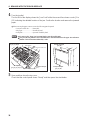
9-1. Removing Any Jammed Paper ................37
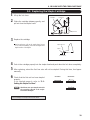
9-2. Replacing the Staple Cartridge................39
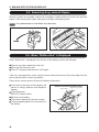
9-3. Removing Any Jammed Staples..............40
9-4. When “Malfunction” is Displayed .............40
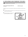
10. Precautions on Use of Emergency Stop
Switch ...............................................................41
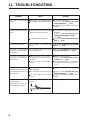
11. Troubleshooting...............................................42
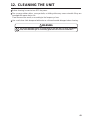
12. Cleaning the Unit .............................................43
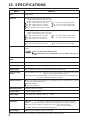
13. Specifications...................................................44

2
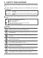
Always observe the cautions and warnings given below to prevent personal injury or property
damage.
The degree of danger and damage that could occur is indicated on two levels by the
following marks.
WARNING : Ignoring this mark could result in the possibility of serious injury or
even death.
CAUTION : Ignoring this mark could result in the possibility of injury or physical
damage.
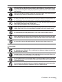
The following graphic symbols indicate the various types of action to be performed or
avoided.
This graphic symbol indicates a forbidden action.
means “Do not disassemble.”
means “Do not touch.”
This graphic symbol indicates actions that must be performed.
means “Disconnect the power plug.”
1. SAFETY PRECAUTIONS
!
!
WARNING:
!
Do not place metal objects or vessels containing liquids on top of the unit. The entry of any
metal object or liquid could result in a fire or an electrical shock.
Do not insert any metal or easily-combustible object inside this unit. This could result in a fire
or an electrical shock.
Do not touch or insert foreign objects into any rotating part during operation. This could
result in injury.
Do not remove the cover or back panel. This unit contains high-voltage components that
could cause an electrical shock.
Do not disassemble, modify or repair this unit. There is a danger of fire, electrical shock or
injury. Contact your dealer when repairs are necessary.
Use only the power supply voltage specified on the main nameplate. Using other voltages
could result in a fire or an electrical shock.
Keep this unit and the power cord away from heaters and heater vents. Excessive heat could
melt the cover or power cord covering, and result in a fire or an electrical shock.
Do not use flammable sprays or solvent inside or near the unit (e.g. when cleaning the unit).
Such flammable gas or solvent may ignite and cause a fire or combustion.

3
Make sure that the combined power consumption of the appliances to be connected does not
exceed the capacity rating of the power outlets or plug receptacles. Exceeding the capacity
rating could cause the power outlets, plug receptacles, or power extension cords to overheat
and catch a fire.
Remove any dust that accumulates on the power plug prongs and the surface of the plug from
which the prongs extend. Accumulated dust could result in a fire.
If any foreign object such as metal or liquid should enter this unit, immediately turn the unit
off at the power switch and disconnect the power plug from the power outlet. Failure to do
so could result in a fire or an electrical shock. Contact your dealer immediately.
Do not damage the power cord or power plug. (Do not scratch, alter, bend, twist, pull or place
heavy objects on the power cord or power plug.)
This could result in damage, a fire or an electrical shock.
Always grip the plug when disconnecting the power plug from the power outlet. Forcibly
pulling on the power cord could cause damage, resulting in a fire or an electrical shock.
Do not handle the power plug with wet hands. This could result in an electrical shock.
Before cleaning this unit, turn the unit off at the power switch and disconnect the power plug
from the power outlet. Accidental operation of the unit during cleaning could result in injury.
CAUTION:
!
Always disconnect the power plug from the power outlet when the unit is not to be used for
an extended period. Failure to do so could result in a fire due to leakage current if the
insulation should deteriorate.
Install this unit on a level, stable stand or floor, with sufficient space around it. Failure to do
so could result in the unit overturning and causing injury.
Do not install this unit in a location where there is excessive humidity or where contact with
water is possible. Poor choice of location could result in deterioration of the insulation, a fire
or an electrical shock.
Disconnect the power plug from the power outlet before attempting to move this unit. Failure
to do so could result in power cord damage, a fire or an electrical shock.
(Continued on the next page)
Do not touch the power switch with wet hands. Otherwise electric hazards may occur.

4
SAFETY PRECAUTIONS (continued)
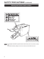
Warning and Caution Label Locations
NOTE : The warning and caution labels are pasted on the unit to ensure the safety of users. Do not remove nor change
them.
If these labels become dirty, damaged, or lost, be sure to contact your nearest dealer for new ones.

5
This equipment shall be installed near the socket-outlet where the plug on the power supply
cord is easily accessible.
Make sure the power supply used is always within the following range.
220 to 240 V AC, 50/60 Hz (120 V AC, 60 Hz)
When you power other appliances from the same AC outlet, make sure that the combined
power consumption does not exceed the power supply capacity.
Rated power of this equipment: 1 A (220 to 240 V AC) / 2 A (120 V AC)
2. USAGE PRECAUTIONS
2-2. Power Supply
Operate this unit in the following environment:
2-3. Operating Environment
Store this unit in the following environment:
2-4. Storage Conditions
To protect the special features of this unit, the customer should never apply oil or grease to the
parts. Please contact your dealer in case of any problem.
2-5. Maintenance
– where the temperature range is between 5 and 35°C
(41 and 95°F),
– where the humidity range is between 20 and 85%
RH (no dew condensation),
– which is not subject to direct sunlight,
– which is subject to little or no vibration,
– where there are no harmful chemicals,
– which is reasonably free from dust,
– which is free from air-borne salt, and
– where the equipment is not exposed to water.
– where the temperature range is between –5 and
+50°C (23 and 122°F),
– where the humidity range is between 10 and 90%
RH (no dew condensation),
– which is not subject to direct sunlight,
– which is subject to little or no vibration,
– where there are no harmful chemicals,
– which is reasonably free from dust,
– which is free from air-borne salt, and
– where the equipment is not exposed to water.
This unit can be connected to a collator, etc. (upstream unit).
2-1. About This Equipment
Do not use flammable sprays or solvent inside or near the unit (e.g. when cleaning the
unit). Such flammable gas or solvent may ignite and cause a fire or combustion.
WARNING
!

6
3. NAMES AND OPERATION OF PARTS
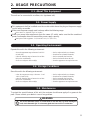
3-1. External Parts
q
e
w
r
t
y
u
i
o
!0
!1
@1
!3
!2
@2
@3
!5
!8
!7
!6
!9
@0
!4

7
When opened during operations, the unit will make an emergency stop.
Refer to “6. OPERATING”.
Side-stapled paper and corner-stapled paper are ejected onto this stacker.
Rejected paper are also ejected here.
Holds the paper sets ejected.
Used for side-stapling and corner-stapling the paper.
Used for side-stapling and corner-stapling the paper.
Saddle-stapled/folded paper and center-folded paper are ejected onto this
stacker.
Conveys saddle-stapled/folded paper and center-folded paper to the saddle-
stapled paper stacker.
Connect the cable of the belt stacker.
Holds the saddle-stapled/folded paper and center-folded paper as an aid for the
belt stacker.
Press this switch only to stop operations in emergency. Normally, use the stop
key of the upstream unit (collator, etc.) to stop operations.
Slot for receiving the paper from the collator.
Slot for inserting the paper manually.
Used for feeding paper manually.
Moves the unit to align the paper lines on the collator and this unit.
Connect the connecting cable from the collator.
Connect the connecting cable from the upstream unit.
Connect the connecting cable from the downstream unit.
Connect the connecting cable from the upstream unit.
Connect the connecting cable from the downstream unit.
Refer to “4-2. When Turning ON the Power”.
Refer to “4-2. When Turning ON the Power”.
Connect the power cord.
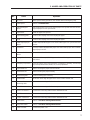
3. NAMES AND OPERATION OF PARTS
No. Name Operation
q
w
e
r
t
y
u
i
o
!0
!1
!2
!3
!4
!5
!6
!7
!8
!9
@0
@1
@2
@3
Top cover
Control panel
Side-stapled paper
stacker
Paper holder
Paper holding guide
Guide
Saddle-stapled paper
stacker
Belt stacker
Connector for belt
stacker
Paper guide roller
Emergency stop switch
Paper infeed slot
Manual feed slot
Manual feed guide
Movable table
Connector for
connecting cable
D-PORT connector 1
D-PORT connector 2
E-PORT connector 1
E-PORT connector 2
Power switch
Main power switch
Power cord inlet

8
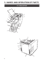
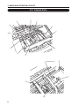
3-2. Internal Parts
3. NAMES AND OPERATION OF PARTS
!5
!4
!3
!0
!1
u
q
w
e
r
t
o
!2
i
y
q
(Opened state)

9
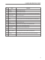
3. NAMES AND OPERATION OF PARTS
Aligns the width of the paper.
Aligns the length of the paper.
Holds the paper in conveyance. Can be removed to remove jammed paper.
Belt to convey the paper.
Roller to drive the conveyance belt and ball unit.
Conveys the paper from the saddle-stapling stopper to the folding stopper.
Staples the paper.
Bends the stapler pin flat.
Stopper used for side-stapling or corner-stapling the paper.
Stopper used for saddle-stapling the paper.
Stopper which decides the folding position.
Roller for folding the paper.
Used for adjusting the clearance between the folding rollers.
Holds the paper. Can be opened and closed to remove jammed paper.
Counts the number of times stapled.
No. Name Operation
q
w
e
r
t
y
u
i
o
!0
!1
!2
!3
!4
!5
Side jogger
Back jogger
Conveyance roller unit
Conveyance belt
Conveyance roller
Ball unit
Stapler head
Clincher
Side-stapling stopper
Saddle-stapling stopper
Folding stopper
Folding roller
Clearance adjusting
lever
Guide plate
Total counter

10
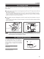
4. CHECK THIS BEFORE USE
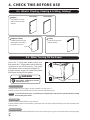
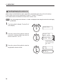
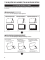
4-1. What is Stapling, Stapling & Folding, Folding?
Stapling
Side-staples or corner-
staples the paper with
staplers.
Stapling & folding
Saddle-staples the paper
with staplers and folds it
along the center line.
Folding
Center-folds the paper
without stapling.
Side-stapling Corner-stapling
Staples
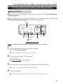
4-2. When Turning ON the Power
Press the “I” of the main power switch, and
then press the “I” of the power switch at the top
of the unit to turn ON the power. The power
ON indicator on the control panel lights up.
If paper remains in the unit, remove the paper
first before turning ON the power.
Main power switch
Switch for turning on power supply to the unit. Normally, leave ON (set to “I”).
Normally use the power switch at the top of the unit to turn ON and OFF the power.
NOTE : To turn OFF the main power, turn off the power using the power switch at the top of the unit before turning
OFF the main power switch.
Power switch
Switch for turning ON and OFF the power of the unit.
(If the downstream unit has a remote function, pressing this switch will also turn ON and OFF the power of the downstream unit
at the same time.)
Remote function
This function is used for turning ON/OFF the power of each unit using just one power switch when linking several processing
units.
Do not touch the power switch with
wet hands. Otherwise electric
hazards may occur.
WARNING
!
Power switch
Main power switch

11
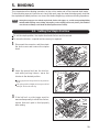
5. BINDING
This chapter describes binding operations in the on-line mode and off-line (manual feed) mode.
To bind another new set, bind one set, check that each page has been bound properly, and that
the stapled and folded positions are correct first before beginning continuous binding operations.
NOTE : Setting the wrong paper size with the stapler head, clincher, side jogger, etc., and the wrong stapling/folding
method (saddle-stapling, center-folding, side-stapling, corner-stapling) will not only lead to poor finish but
cause the unit to damage as well. Read the following instructions carefully.
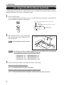
5-1. Setting the Staple Position
To set the staple position, the stapler head and clincher must be moved.
To move the clincher, a special tool (accessory) is required.
Disconnect the connector, and then rotate
the knob screw and remove the stapler
head.
Insert the special tool into the clincher,
and while pushing it down, move the
clincher to the desired position.
Set the projection of the special tool to the position to
be set.
Lift up the special tool slightly and swing it to the left
and right. The clincher will stop.
Stapler head
Connector
Knob screw
Special tool
Projection
1
2
Clincher
If the ball unit or side jogger must be
removed temporarily to move the clincher,
ensure that each part is fixed properly
after setting.
3
Ball unit
Side jogger

12
5. BINDING
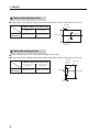
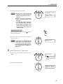
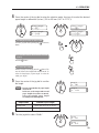
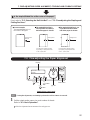
Setting saddle-stapling position
The position to be stapled is determined after setting the center of the paper on the unit.
Paper Width
(mm (inch))
Settable Staple Pitch (mm (inch))
108 (4.25)
Above 200 (7.87)
Setting side-stapling position
Staples within 6 mm (0.24") from the lead edge of the paper.
The position to be stapled is determined after setting the center of the paper on the unit.
Paper width
Staples
Direction
moved in
Staple pitch
Staples
Direction
moved in
Staple pitch
6 mm (0.24")
Paper width
160 (6.30)
Above 252 (9.92)
Paper Width
(mm (inch))
Settable Staple Pitch (mm (inch))
108 (4.25)
Above 200 (7.87)
160 (6.30)
Above 252 (9.92)

13
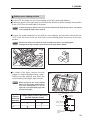
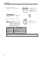
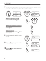
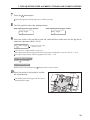
Setting corner-stapling position
A4 and LTR size paper can be corner-stapling only if fed in wide edge leading.
Staples the paper on the right corner as seen from the direction in which the paper moves within
6 mm (0.24") from the lead edge of the paper.
NOTE : To staple the paper on the left corner as seen from the direction in which the paper moves, the optional
corner-stapling side jogger (left) is required.
As shown in the figure, remove the side
jogger for saddle-stapling/folding, center-
folding, and side-stapling. And attach the
corner-stapling side jogger (right) instead.
NOTE : When setting from the corner-stapling
mode to the side-stapling, saddle-stapling,
and center-folding modes, be sure to
replace the corner-stapling side jogger with
the normal side jogger.
Remove the stapler head which is not used for corner-stapling, and secure the clincher 80 mm
(3.15") from the center of the unit. And set the corner-stapling guide (accessory) at the same
position.
NOTE : Should not use stapler head without the staple cartridge instead of the corner-stapling guide.
Stapling with the staple cartridge removed will cause the stapler head to damage.
Corner-stapling guide (accessory)
5. BINDING
<Corner-stapling guide (accessory)>
Settable Staple Position (mm (inch))
(Position from the Center)
A4
LTR
130 (5.12)
×
Paper Size
(Feed in
landscape
direction)
Ball unit
Direction
moved in
130 or 140 mm
(5.12" or 5.51")
80 mm (3.15")
Staple
Clincher,
corner-stapling
guide
6 mm (0.24")
140 (5.51)
×
Corner-stapling side jogger
(right)
Direction moved by paper

14
1
2
3
4
5
6
7
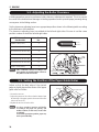
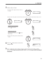
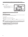
5-2. Adjusting the Roller Clearance
If folding operations are to be performed, roller clearance adjustment is required. This is to prevent
the cover of the booklet from damages in binding operations and to prevent paper jamming during
conveyance at the folding section.
Set the clearance adjusting lever to an appropriate position shown in the following table according
to the thickness of the booklet.
The clearance adjusting lever is provided at the left and right sides. Be sure to set the same
position number for both the left and right sides.
Thickness of
One Booklet
Lever Position
No.
Below 1.7 mm (0.07")
1.5 to 2.7 mm (0.06" to 0.11")
2.5 to 3.5 mm (0.10" to 0.14")
3.2 to 4.0 mm (0.13" to 0.16")
3.7 to 4.5 mm (0.15" to 0.18")
4.2 to 5.0 mm (0.17" to 0.20")
Above 4.7 mm (0.19")
1
2
3
4
5
6
7
NOTE : Since conditions change according to the
paper quality, the setting position of the lever
may differ from the above table.
5. BINDING
Clearance adjusting lever
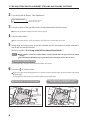
5-3. Setting the Position of the Paper Guide Roller
Adjust so that the lead edge of the ejected
paper is slightly beyond the center of the paper
guide roller as follows.
q Loosen the set screw.
w Adjust the position of the roller so that the distance from
the lead edge of the paper ejected to the center of the roller
is about 30 mm (1.18").
e Tighten the set screw to fix the roller.
NOTE : As above standard position will differ
according to the paper size, quality, and
number of sheets, in such cases, set the roller
accordingly.
If not at the appropriate position, paper may
not be ejected smoothly.
Booklet
thickness
Set screw
Paper guide roller
About 30 mm
(1.18")

15
5. BINDING
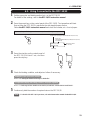
5-4. Using the Guide
When side-stapling is performed, set the guides and paper holding guide on the side-stapled
paper stacker.
Place the paper on the stacker. And set the guides about 20 mm (0.79") away from the left and
right sides of the paper.
Next, set the paper holding guide about 50 mm (1.97") away from the lead edge of the paper.
However, the position of the guides and paper holding guide may change according to the paper
quality and number of sheets to be processed.
Set the guides and paper holding guide so that the curved in part faces outwards as shown in
the figure.
Set the curved in part inwards only when the paper is too big and the guides and paper holding
guide cannot be set.
Paper holding guide
Guides
Side-stapled
paper stacker
Paper holding guide
Guides
Paper
20 mm (0.79")
50 mm
(1.97")
Side-stapled paper stacker
5-5. Selecting the Ball Unit Ball
The standard plastic ball is set at shipment. If
the stapling position shifts or if paper jams
when the paper is conveyed from the stapling
to folding section, change to the steel ball
provided.
To increase the conveyance force
Use the steel ball.
To decrease the conveyance force
Use the standard plastic ball.
Ball unit
Ball
20 mm (0.79")
NOTE : The paper stacking height for the side-stapled paper stacker is about 90 mm (3.54").
As stacking paper more than this height will cause paper to jam, remove accumulated paper when performing
continuous operations to ensure this height is not exceeded.

16
6. OPERATING
Stapler folder control panel
6-1. Basic Operation
Select the output mode.
Use the jog dial on the stapler folder control panel for this setting.
1
Example of stapling and folding six A4 size sheets of paper
Output Mode
Booklet
The second line shows the
currently set output mode.
q Turn the jog dial to display “Output Mode” in the
display.
w Press the center of the jog dial.
Select Mode
Booklet Side ST
Start button
Stop button
button
Clear
button
Escape
Jog dial
Power ON indicator
Lights up when the stapler
folder is turned ON.
Display
button
Function
Booklet A3 2
Ready

17
6. OPERATING
e Turn the jog dial to select “Booklet”.
NOTE :
Even when you have selected
“Booklet”, the paper will only be
folded (not stapled) if you select “1”
in step 3.
If the “Through” is selected, the
paper is ejected without being
processed.
The paper size cannot be changed in
the “Through” mode. Therefore
before using the “Through” mode,
change to the desired paper size in
output modes other than the
“Through” mode.
To cancel the setting
Instead of going on to step r, press the (Escape)
button to return to step q.
Select Mode
Booklet Side ST
The selected output mode shifts
to the beginning of the line and
starts blinking.
r Press the center of the jog dial to confirm the
selection in step e.
NOTE : If the paper size set when selecting the
output mode is not suitable for the
output mode, priority will be given to
the output mode, and the paper size
will automatically be changed to a
suitable size.
Output Mode
Booklet
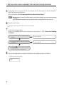
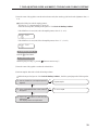
Set the paper size to be processed.
q Turn the jog dial to display “Paper Size” in the
display.
2
Paper Size
A3
w Press the center of the jog dial.
Select P. Size
A3 A4 A5 B4 B5
The paper size displayed in
the second line is currently
selected.

18
6. OPERATING
r Press the center of the jog dial to confirm the paper
size.
NOTE : In some output modes, the paper size
cannot be set.
In this case, as the output mode set
and paper size selected do not match,
select the suitable paper size
according to the following table.
Paper Size
A4
e Turn the jog dial to select the size.
If the paper size to be set is not a standard size, select
“Custom”.
Select P. Size
A4 A5 B4 B5 LGR
To cancel the setting
Instead of going on to step r, press the button to
return to step q.
The selected paper size shifts to
the beginning of the line and
starts blinking.
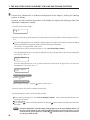
When “Custom” has been selected, perform the “ Presetting/changing the custom size” on the next
section.
Booklet, Fold A3SR, A3, B4, A4, LGL, LTR, LGR
Side ST A4, B5, A5, LTR, IV
Corner ST A4, LTR
Output Mode Settable Paper Size
La pagina si sta caricando...
La pagina si sta caricando...
La pagina si sta caricando...
La pagina si sta caricando...
La pagina si sta caricando...
La pagina si sta caricando...
La pagina si sta caricando...
La pagina si sta caricando...
La pagina si sta caricando...
La pagina si sta caricando...
La pagina si sta caricando...
La pagina si sta caricando...
La pagina si sta caricando...
La pagina si sta caricando...
La pagina si sta caricando...
La pagina si sta caricando...
La pagina si sta caricando...
La pagina si sta caricando...
La pagina si sta caricando...
La pagina si sta caricando...
La pagina si sta caricando...
La pagina si sta caricando...
La pagina si sta caricando...
La pagina si sta caricando...
La pagina si sta caricando...
La pagina si sta caricando...
La pagina si sta caricando...
-
 1
1
-
 2
2
-
 3
3
-
 4
4
-
 5
5
-
 6
6
-
 7
7
-
 8
8
-
 9
9
-
 10
10
-
 11
11
-
 12
12
-
 13
13
-
 14
14
-
 15
15
-
 16
16
-
 17
17
-
 18
18
-
 19
19
-
 20
20
-
 21
21
-
 22
22
-
 23
23
-
 24
24
-
 25
25
-
 26
26
-
 27
27
-
 28
28
-
 29
29
-
 30
30
-
 31
31
-
 32
32
-
 33
33
-
 34
34
-
 35
35
-
 36
36
-
 37
37
-
 38
38
-
 39
39
-
 40
40
-
 41
41
-
 42
42
-
 43
43
-
 44
44
-
 45
45
-
 46
46
-
 47
47


Duplo DBM-120 Manuale utente
- Categoria
- Macchine piegatrici
- Tipo
- Manuale utente
in altre lingue
- English: Duplo DBM-120 User manual
Documenti correlati
Altri documenti
-
Hitachi N 5024A2 Manuale utente
-
-
Minolta EP2030 Manuale utente
-
-
KYOCERA TASKALFA 820 Manuale utente
-
Utax CD 1025 Istruzioni per l'uso
-
Martin Yale papermonster F200 Operating Instructions Manual
-
KYOCERA DF-610 Manuale del proprietario
-
-
MG MERO 18 P Operating Instructions Manual