MG MERO 18 P Operating Instructions Manual
- Categoria
- Cucitrici
- Tipo
- Operating Instructions Manual

OPERATING INSTRUCTIONS
Pneumatic Carton Stapler for coiled staples
MERO 18 P + MERO 22 P
Page: 1
Mod.: 804
ET 675, 676
Page 1 of 6 04.05.2018
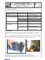
Model
Size of tool
(mm)
Weight
(kg)
Staples
32 mm crown size
for single and light double
corrugated cardboard
for double corrugated
cardboard
MERO 18 P
233 x 230 x
115
2,37
R 1/58 = 15 mm
R 1/34 = 18 mm
Leg length:15 mm, 18 mm, Capacity: 1000 staples
for double corrugated
cardboard
for double and light triple
corrugated cardboard
MERO 22 P
233 x 230 x
115
2,37
R 1/34= 18 mm
R 1/78 = 22 mm
Leg length: 18 mm, 22 mm Capacity: 1000 staples
E:\Bedienungsanleitungen\MERO Bedienungsanl. deutsch-englisch 104\Bedien MERO 22 P englisch 104.doc
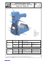
1) Cap
2) Body
3) Collar
4) Adjustment Plate
5) Adjusting Rod
6) Magazine Seat
7) Cover
8) Trigger
1
2
3
4
5
6
7
8

OPERATING INSTRUCTIONS
Pneumatic Carton Stapler for coiled staples
MERO 18 P + MERO 22 P
Page: 2
Mod.: 804
ET 675, 676
Page 2 of 6 04.05.2018
1 Usage
Pneumatic stapling tool for fastening the flaps of filled cartons of single, double or light triple corrugated
cardboard boxes.
2 Important note
It is the customer’s responsibility to have all operators and service personnel read and understand this
manual. This stapling tool may only be used by specially advised persons (s. Annex).
Prior to first use, please lubricate all movable parts, then insert staples (s. Chapter 3.3). The air supply
should be connected with a quick release coupling. It is operated by a motive agent (compressed air). This
stapling device is made solely for normal operation in industrial spheres or similar areas (use as directed).
The tool should be fitted with a maintenance unit with pressure regulator, air cleaner and oil spray units to
ensure smooth trouble free operating and long life.
2.1 Environmental conditions
The tool should be used with indoor conditions (room temperature, etc.). Usage within explosive
atmosphere is only permitted with the manufacturer’s prior approval.
2.2 Emission
The noise level is max. 93 dB(A) (L WA, Is). Heterogeneous gases will not be emitted by the stapling
device.
2.3 Technical Data
Connection: 1/4´´
Operation pressure: 5 - 7 bars; max. 8 bars
Air consumption: 1,1 NL/stapling
2.4 Safety instructions
COUTION: Keep your hands away from base of the machine at all times! Danger of injury!
Never exceed the recommended maximum pressure for the stapling tool.
Do not attempt to use a defective stapling tool.
Never load the stapling tool until you are ready to use it.
Never attempt to fasten into very hard or brittle material such as concrete, steel or tile etc..
Use only clean, dry regulated COMPRESSED AIR. Never use oxygen, carbon dioxide or other
bottled gases.
Always disconnect the tool from the air supply and empty magazine before: work breaks - changing
parts - servicing stapling tool.
3 Operating Instructions
3.1 Functional description
The stapling tool should be fitted with maintenance unit. The maintenance unit should be adjusted to one
drop lubrication, e.g. Unocal RX 22, per 40-50 machine cycles.
The stapler MERO 18 P can be used with the following coiled staples: R 1/58, R 1/34.
The stapler MERO 22 P can be used with the following coiled staples: R 1/34, R 1/78.

OPERATING INSTRUCTIONS
Pneumatic Carton Stapler for coiled staples
MERO 18 P + MERO 22 P
Page: 3
Mod.: 804
ET 675, 676
Page 3 of 6 04.05.2018
3.2 Handling
Insert staples into the magazine (7) (s. Chap. 3.3). Adjust the stapling tool as required (s. Chap. 3.4 - 3.6).
Place the stapler MERO 18 P or MERO 22 P on top of the carton to be sealed in a way that the flap joint
is directly in the centre of the stapling tool (s. arrow in the front of stapler). Then activate trigger (8) to
release stapling. The anvils will extend, clinch the staples and return automatically into the tool. Release
trigger (8). Then move the tool to the next stapling position.
For an optimal fastening result apply staples approx. 1cm to the rim of the carton.
Caution: The stapler should only be moved with the anvils completely returned into the tool
to avoid damage to the retractable anvils!
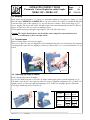
3.3 To load staples
Before inserting staples disconnect air supply!
The cover (7) has to be squeezed slightly and folded backward. Insert the coil as shown into the magazine
seat and push the staples into the stapling tool until stop. Then fold the cover (7) forward until the cover is
locked.
3.4 Adjusting leg length of staples
Before adjusting disconnect air supply!
Loosen screw with hexagonal recessed hole (I) with 3 mm hexagon spanner, turn the adjusting rod (5)
180° with a screw driver to the required position. For long leg length turn adjusting rod (5), so that L is in
upright position, for short leg length turn adjusting rod (5), so that S is in upright position. Fasten the
screw again with hexagonal recessed hole (I).
8
5
7
Staple coil
7
MERO 18 P
Leg length
15 mm
R 1/58
18 mm
R 1/34
MERO 22 P
Leg length
18 mm
R 1/34
22 mm
R 1/78
adjusting
rod -
position
S
L
S
L
I
5

OPERATING INSTRUCTIONS
Pneumatic Carton Stapler for coiled staples
MERO 18 P + MERO 22 P
Page: 4
Mod.: 804
ET 675, 676
Page 4 of 6 04.05.2018
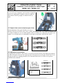
Loosen screws (S) in magazine seat (6) and move right (R)
and left (L) stapling plate outward for long leg length (18)
and inward for short leg length (15). Fasten screws (S)
again.
3.5 Staple clinch control (closed or open clinch)
Should adjustment of the staple clinch be necessary, it
should be carried out as follows: turn collar (3) with a matching tool (W), e.g. 2,5 mm rod, turn the collar
(3) counter clockwise for a looser clinch, turn the collar (3) clockwise for a tight clinch. For thick carton
quality a looser clinch may be recommendable as the staple can penetrate deeper into the carton.
3.6 Adjustment of penetration
For adjusting the penetration of the anvils loosen front screw (F) by means of a 6 mm hexagon spanner
(I). Move body up or down into the required position. Fasten front screw (F) again. If the body (2) is in
the upper position, the stapling penetration (A) is maximal. If the body (2) is in the lower position,
penetration (B) is minimal.
F
2
Tight clinch
Looser clinch
Middle position for optimal clinch
B
A
A = penetration adjustment
B = anvil
C = staple
Tight clinch
offene Heftung
R
S
L
W
3
open clinch
open clinch

OPERATING INSTRUCTIONS
Pneumatic Carton Stapler for coiled staples
MERO 18 P + MERO 22 P
Page: 5
Mod.: 804
ET 675, 676
Page 5 of 6 04.05.2018
3.7 Malfunction check list
For regulations, disassembly or repairs, always disconnect tool from air installation.
Malfunction
Cause
How to clear
Air leakage of trigger/Cylinder/
exhaust port
O-ring/s is/are defect
Remove O-rings
Send stapler to manufacturer
Slow and short travel cycling
Trigger defect or loose
Fasten screws, exchange trigger
Jammed staples
Trigger defect or loose
Fasten screws, exchange trigger
Send stapler to manufacturer
Screws at anvils loose
Fasten screws
Wrong staple size adjusted
Adjust correct staple size
Insufficient lubrication
Lubricate moving parts
Uneven clinch
Wrong staple size adjusted
Adjust stapling accord. to chapter 3.4
– 3.6.
Unclinched staple
Anvils defective or loose
Fasten screws at anvils or exchange
anvils.
Send stapler to manufacturer.
Trigger defective or loose
Fasten screws at trigger or exchange
trigger.
Send stapler to manufacturer.
3.8 De-jamming
Should a staple jam inside the tool, do not trigger any more. This can damage the anvils. Disconnect air
supply. Turn lever (H) as shown. Remove the jammed staples with an according tool, e.g. a spanner.
In case of severe jamming the driver guidance unit 27 can also be removed to gain more space for
clearing the jamming (may be removed quite easely as it is only fixed on 2 bolts. Then turn lever (H) in
the original position. Connect air supply. The machine is now ready for stapling again.
3.9 Unauthorized application and operation
Use stapler only for the defined materials and operations. Use only original staples.
If the stapling tool is not used as directed, the manufacturer is not liable for any damage
H
Plunger
Guide
unit 27

OPERATING INSTRUCTIONS
Pneumatic Carton Stapler for coiled staples
MERO 18 P + MERO 22 P
Page: 6
Mod.: 804
ET 675, 676
Page 6 of 6 04.05.2018
resulting from this undue use. Any risk of damage is borne solely by the user.
Use as directed also means observing the operating, servicing and maintenance conditions laid down by
the manufacturer of the tool.
The stapler may only be used, maintained and repaired by persons who are familiar with it and have been
advised of the dangers.
The relevant accident prevention regulations as well as other generally recognized industrial safety and
medical regulations must be observed.
Unauthorized modifications to this stapler or the use of spare parts or staples which are not original parts
from the manufacturer exclude any liability of the manufacturer for any resultant damage.
3.10 General Instructions
When not in use disconnect air supply and remove all staples.
Important - General Instructions
It is the customer’s responsibility to have all operators and service
personnel read and understand this manual.
MG tools are ruggedly built for long, dependable operation.
Details about safety as well as all necessary information for the tool’s
proper care and general maintenance are contained in this book.
Safety rules
NEVER exceed the recommended maximum pressure for the tool
(normally 6 bars).
DO NOT attempt to use a defective stapler.
NEVER load the stapler until you are ready to use it
DO NOT reload when you release a stapling operation
Only operate the tool when in contact with the carton surface.
At all times keep hands clear of base of machine whilst activating trigger.
Do not attempt to staple on to hard surface.
NEVER USE oxygen, combustible gases or high pressure compressed gas
tanks as air supply for the tool
Always disconnect air supply and empty magazine before: work breaks,
changing parts, servicing tools or clearing a jammed staple, storing tool at
the end of the day
ALWAYS utilise couplers on the compressor side of the air supply
system (couplers when disconnected automatically shut off the flow of
air)
4 Maintenance and Personal Safety Instructions (training, education)
Operation and usage of the stapler is only allowed to specially advised and trained persons.
For maintenance: Always disconnect the tool from the air supply.
For repair use only original spare parts from the manufacturer (s. spare parts list).
The following actions/inspections have to be regularly accomplished by specially advised and trained
persons:
Clean stapler regularly
Oil all movable parts weekly (no oil containing graphite!).
Check the pneumatic operating unit. Refill oil and remove water if necessary.
The pneumatic operating unit should be adjusted to one oil drop per 40-50 machine cycles.
Remark: Advised and trained persons are those who have the education and the experience to use
stapling tools. They have also knowledge of governmental safety and accident prevention instructions
and technical guidelines as DIN, etc. They can also judge function and operating reliability of staplers.
5 Shut down instructions
If the stapler will not be used disconnect air supply and remove all staples.

Seite 1 von 1 P:\Technik\MERO\Stücklisten\2017\Juli\Deckblatt PL MERO 18_22 P.docx
MEZGER Heftsysteme GmbH
Saganer Straße 24 Postfach (P.O.B.) 551170
D-90475 Nürnberg D-90218 Nürnberg
Tel.: +49 911 98494 0 Fax: +49 911 984 94 30
Mail: [email protected] Internet: www.mezger.eu
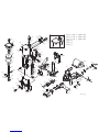
Stückliste
Spare Parts List
MERO 18/22 P
pneumatisch/pneumatic

MODEL: RAIA-19-GR & RAIA-22-GR / MERO 18P & 22P
Item
Parts No.
Beschreibung
Description
Q'ty
Spec.
001
A01200110
Deckel
CAP
1
002
A02800201
Kolben
PISTON
1
003
A02800301
Kolbenstange
PISTON ROD
1
004
A00100401
Zwischenstück
BLOCK
1
005
A00100501
Feder
SPRING
1
006
A00100601
Manschette
COLLAR
1
007
ADCS-P31
Zylindergehäuse
BODY UNIT
1
1/4"-18NPT
008
A00100803
Nippel
AIR PLUG
1
009
A00100902
Zwischenstück
BLOCK
1
010
A00101001
Feder
SPRING
1
011
A00101101
Auslösehebel
TRIGGER
1
012
A00101201
Feder
SPRING
1
013
A00101301
Verbindungsbolzen
ROD
1
014
A00101402
Kontrollhebel
TRIGGER'S CONTROL
1
015
A00101501
Feder
SPRING
1
016
A00101601
Ventil
VALVE
1
017
A00101702
Ventilrohr
TUBE
1
018
A00101801
Einstellbolzen
ADJUSTING ROD
1
019
A00101901
Einstellplättchen
ADJUSTING PLATE
1
020
A01102501
Vorderplatte
FRONT PLATE
1
18P
020
A01102503
Vorderplatte
FRONT PLATE
1
22P
021
A00102102
Greifer rechts
RIGHT TEETH
1
18P
022
A00102202
Greifer links
LEFT TEETH
1
18P
021
A01200501
Greifer rechts
RIGHT TEETH
1
22P
022
A01200601
Greifer links
LEFT TEETH
1
22P
023
A00102301
Greiferhalter
TEETH SEAT
2
024
A00102401
Greifergelenk
PLATE
2
025
A03700902
Treiberblock
DRIVER
1
027
A03600102
Treiberführung
DRIVER GUIDE
1
029
A02300404
Formblock
ANVIL
1
030
A03600202
Vorschub
PUSHER
1
031
A02201101
Feder
SPRING
2
032
A02200501
Vorschubblock
ANVIL CAP
1
033
A02201201
Feder
SPRING
1
034
A02200901
Platte
PLATE
1
035
A02202901
Federhalter
TOP GUIDE
1
036
A02201803
Blattfeder
LEAF SPRING
1
037
A02300605
rechte Klammernführung
RIGHT COIL GUIDE
1
18P
037
A03700601
rechte Klammernführung
RIGHT COIL GUIDE
1
22P
038
A02300705
linke Klammernführung
LEFT COIL GUIDE
1
18P
038
A03700701
linke Klammernführung
LEFT COIL GUIDE
1
22P
039
A03600505
Magazin
MAGAZINE SEAT
1
040
A02201301
Befestigungsschaft
SHAFT
1
041
A02201905
Unterlegscheibe
WASHER
1
T =
1.35㎜
042
A02200801
Bolzen
SHAFT
1
043
A02201001
Arretierhebel
LEVER
1
044
A02201402
Abdeckung
COVER
1
045
A02300801
Platte
PLATE
2
47
A02202402
Scheibe
WASHER
2
48
BAI1401
Schalldämpfer
SILENCER
1
501
BAC0604142
Sechskantschr. M4 x 0,7-14
HEX.SOC.HD.BOLT
4
M4 x 0.7-14
503
BAB017537
O-Ring 1,78 x 53,7
O-RING
1
φ1.78 x φ53.7
504
BAD02061
Sechskantmutter M6 x 1
HEX.NUT
1
M6 x 1
505
BAE06094
Scheibe 1/4" x 5/8"x 1T
WASHER
1
1/4" x 5/8" x 1T
506
BAB017076
O-Ring DM 1,78 x DM 7,65
O-RING
1
φ1.78 x φ7.65
507
BAB057476
O-Ring 5,7 x 47,6
O-RING
1
φ5.7 x φ47.6
508
A00104101
Unterlegscheibe 8 x 23 x 1,6
WASHER
1
φ8 x φ23 x 1.6T
510
BAC0604102
Sechskantschraube
HEX.SOC.HD.BOLT
1
M4 x 0.7-10
511
BAA025014
Federstift DM 2,5 - 14
SPRING PIN
1
φ2.5-14
512
BAC0312122
Sechskantschr. M12 x1,75-12
HEX.SOC.HDLESS.
1
M12 x 1.75-12
BOLT

MODEL: RAIA-19-GR & RAIA-22-GR / MERO 18P & 22P
Item
Parts No.
Beschreibung
Description
Q'ty
Spec.
513
A00104401
Auslösehebelschr M4 x0,7- 7
TRIGGER SCREW
2
M4 x 0.7-7
514
BAE01042
Federscheibe M4
SPRING WASHER
2
M4
515
BAA030020
Federstift pin DM 3-20
SPRING PIN
1
φ3-20
516
BAE02042
äuß GreiferbeilagscheibeM4
OUTSIDE TEETH WASHER
1
M4
517
BAC0404102
Sechskantschr. M4 x 0,7-10
HEX.SOC.HD.BOLT
1
M4 x 0.7-10
518
BAA030010
Federstift DM 3-10
SPRING PIN
1
φ3-10
519
BAB017124
O-ring 1,78 - 12,42
O-RING
1
φ1.78 x φ12.42
520
BAB017076
O-Ring DM 1,78 x DM 7,65
O-RING
2
φ1.78 x φ7.65
521
BAB016145
O-Ring 1, 6 - 14,5
O-RING
1
φ1.6 x φ14.5
522
BAB016150
O-Ring 1, 6 - 15
O-RING
1
φ1.6 x φ15
523
BAB016155
O-Ring 1 ,6 - 15,5
O-RING
1
φ1.6 x φ15.5
524
BAB016160
O-Ring 1 ,6 - 16
O-RING
1
φ1.6 x φ16
525
A00104702
Stange 4,9 - 17,5
ROD
2
φ4.9-23
526
BAC0306142
Sechskantschr. M 6 x 1-14
HEX.SOC.HDLESS.
1
M6 x 1-14
BOLT
527
BAC0608162
Sechskantschraube
HEX.SOC.HD.BOLT
1
M8 x 1.25-16
528
BAA050014
Federstift DM 5-14
SPRING PIN
2
φ5-14
529
BAA030010
Federstift DM 3-10
SPRING PIN
4
φ3-10
530
BAC0605142
6.schr. M5 x 0,8-14
HEX.SOC.HD.BOLT
6
M5 x 0.8-14
531
BAD01051
Mutter
LOCK NUT
1
M5 x 0.8
532
A00106201
6.-Senkschraube M5 x 0,8-12
HEX.SOC.FLAT COUNTER
2
M5 x 0.8-12
SNK HD.SCREW
533
A00104501
Stift 3,98 - 13
PIN
4
φ3.98-13
534
A00104602
Stift 6,05 - 8
PIN
2
φ6.05-8
537
BAA060016-R
Federstift
SPRING PIN
2
φ6-16
538
BAA040022
Federstift 4 - 22
SPRING PIN
3
φ4-22
540
BAC0205202
6-Senkschraube M 5x0,8-20
HEX.SOC.FLAT COUNTER
1
M5 x 0.8-20
SNK HD.SCREW
541
BAC0205082
6-Senkschraube M 5x0,8-8
HEX.SOC.FLAT COUNTER
4
M5 x 0.8-8
SNK HD.SCREW
542
BAC0703063
Senkschraube
ROUND HD.SCREW
4
M3 x 0.5-6
543
BAF10252
E-Ring 2,5
E-RING
2
φ2.5
544
BAA040020
Federstift 4 - 20
SPRING PIN
1
φ4-20
545
BAF22002
C-Ring
C-RING
1
φ20
孔用
546
BAF10252
E-Ring 2,5
E-RING
1
φ2.5
548
A00104901
Plastik-Stift
PLASTIC PIN
1
549
A02203102
Unterlegscheibe 8
WAVE WASHER
1
φ10.5
550
C0011201A
Aufhängung
COUNTER BALANCE HANGER
1
551
BAF22002
C-Ring
C-RING
1
φ20
552
BAI1305
LUFTSTECKER ADAPTER
AIR PLUG ADAPTOR
1
1/4"-18NPT→1/4"-19PT

626
628
621
622
659
131 637
612
112
118
614
115
615
616
617
113
618
114
619
625
624
T
129
M
661
623
159
662
126
657
629
62:
631
127
636
627
123
11:
121
124
122
134
128
645
125
632
634
635
633
116
117
638
63:
12: 5
3
2
4
641
656
SBJB.2:.SS!)2/:ϩØ1/:ϩ*
SBJB.33.HS!)3/4ϩØ1/:ϩ*
SBJB.2:.HS!)3/4ϩØ1/:ϩ*
653
119
644
643
133 135
SBUB.2:
SBTB.2:
148
143
156
13:
649
138
141
132
142
145
144
652
149
654
14:
151
648
136
158
147
146
639
642
651
SBTB.23
155!
3125023022
154
153
655
152
65:
663

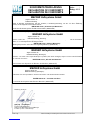
KONFORMITÄTSERKLÄRUNG
DECLARATION OF CONFORMITY
DECLARATION DE CONFORMITE
Seite: /
Ändrg.: 0313
ET
06.03.13 hg C:\Daten Gumbinger\Verwaltung\Konformitaet\Konformitaet 0313.doc
Der Hersteller bzw. Importeur dieses pneumatischen Heftgerätes, die Firma
erklärt in alleiniger Verantwortung, daß das Produkt (s. Bedienungsanleitung), auf das sich diese Erklärung
bezieht, mit der folgenden Norm übereinstimmt:
DIN EN ISO 12100: „Sicherheit von Maschinen“
gemäß den Bestimmungen der EG-Maschinenrichtlinie (2006/42 EG).
The manufacturer resp. importer of this pneumatic stapling tool, the company
declares under sole responsibility that the product (see attached instruction manual), to which the declaration
relates, is in confirmity with the following standard:
DIN EN ISO 12100: „Safety of Machinery“
following the provisions of the Directive Regarding Machinery (2006/42 EC).
Nous, le manufacteur resp. importeur de cet appareil pneumatique, la maison
déclarons sous notre seule responsabilité que le produit (selon mode d'emploi) auquel se réfère cette déclaration
est conforme a la norme
DIN EN ISO 12100: „Sécurité des Machines“
Conformément aux dispositions de Directive des Machines (2006/42 CE).
Noi
dichiariamo che chesto prodotto è conforme alle norme o ad altri documenti normativi
DIN EN ISO 12100: « sicurezza macchina »
In conformita alle dispoizioni delle Directiva Macchine (2006/42 CE).
MEZGER Heftsysteme GmbH
Saganer Straße 24
D-90475 Nürnberg
MEZGER Heftsysteme GmbH
Saganer Straße 24
D-90475 Nürnberg (Germany)
MEZGER Heftsysteme GmbH
Saganer Straße 24
D-90475 Nürnberg (Allemagne)
Nürnberg, 07.03.13
................................................................................................
ppa/p.p. Gumbinger
Prokurist und Unit Manager
Authorised representative and Unit Manager
Fondé de pouvoir et Unit Manager
MEZGER Heftsysteme GmbH
Saganer Straße 24
D-90475 Nürnberg (Allemagne)
-
 1
1
-
 2
2
-
 3
3
-
 4
4
-
 5
5
-
 6
6
-
 7
7
-
 8
8
-
 9
9
-
 10
10
-
 11
11


MG MERO 18 P Operating Instructions Manual
- Categoria
- Cucitrici
- Tipo
- Operating Instructions Manual
in altre lingue
- English: MG MERO 18 P
Altri documenti
-
Hitachi N 5024A2 Manuale utente
-
-
Parkside PET 25 A1 Operation and Safety Notes
-
Parkside PET 25 B1 Operation and Safety Notes
-
Parkside PDT 40 A1 Operation And Safety Notes Original Operating Instructions
-
-
Duplo DBM-120 Manuale utente
-
Stanley TRE550 Manuale del proprietario
-
Parkside 331116_1907 Translation Of The Original Instructions
-