
© Copyright 2003, Zenith Electronics Corporation
Installation and Operating Guide | Warranty
Model Numbers | H27F56DT | H27F56S | H32F56S | H32F56DT |
Direct View TVs
table of contents
page
5

WARNING:
TO REDUCE THE RISK OF ELECTRIC SHOCK DO NOT REMOVE COVER (OR BACK). NO USER SERVICEABLE PARTS INSIDE.
REFER SERVICING TO QUALIFIED SERVICE PERSONNEL.
The lightning flash with arrowhead symbol, within an equilateral triangle, is intended to alert the user to the presence of
uninsulated “dangerous voltage” within the product’s enclosure that may be of sufficient magnitude to constitute a risk of
electric shock to persons.
The exclamation point within an equilateral triangle is intended to alert the user to the presence of important operating and
maintenance (servicing) instructions in the literature accompanying the appliance.
WARNING:
TO PREVENT FIRE OR SHOCK HAZARDS, DO NOT EXPOSE THIS PRODUCT TO RAIN OR MOISTURE.
POWER CORD POLARIZATION:
CAUTION: To prevent electric shock, match wide blade of plug to wide slot, fully insert.
ATTENTION: Pour éviter les chocs électriques, introduire la lame la plus large de la fiche dans la borne
correspondante de la prise et pousser jusqu’au fond.
NOTE TO CABLE/TV INSTALLER:
This reminder is provided to call the cable TV system installer’s attention to Article 820-40 of the National Electric Code
(U.S.A.). The code provides guidelines for proper grounding and, in particular, specifies that the cable ground shall be
connected to the grounding system of the building, as close to the point of the cable entry as practical.
REGULATORY INFORMATION:
This equipment has been tested and found to comply with the limits for a Class B digital device, pursuant to Part 15
of the FCC Rules. These limits are designed to provide reasonable protection against harmful interference when the
equipment is operated in a residential installation. This equipment generates, uses and can radiate radio frequency
energy and, if not installed and used in accordance with the instruction manual, may cause harmful interference to radio
communications. However, there is no guarantee that interference will not occur in a particular installation. If this equip-
ment does cause harmful interference to radio or television reception, which can be determined by turning
the equipment off and on, the user is encouraged to try to correct the interference by one or more of the following
measures:
• Reorient or relocate the receiving antenna.
• Increase the separation between the equipment and receiver.
• Connect the equipment into an outlet on a circuit different from that to which the receiver is connected.
• Consult the dealer or an experienced radio/TV technician for help.
CAUTION:
Do not attempt to modify this product in any way without written authorization from Zenith Electronics Corporation.
Unauthorized modification could void the user’s authority to operate this product.
COMPLIANCE:
The responsible party for this product’s compliance is:
Zenith Electronics Corporation, 2000 Millbrook Drive, Lincolnshire, IL 60069, USA • Phone: 1-847-941-8000.
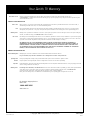
RECORD YOUR MODEL NUMBER
The model and serial numbers of this TV are located on
the back of the TV cabinet. For your future convenience,
we suggest that you record those numbers here:
MODEL NO.____________________________________
SERIAL NO.____________________________________
© Copyright 2003 Zenith Electronics Corporation
For Customer Support/Service please call:
1-888-865-3026
www.zenith.com
2-WIRE DWARN 3/01
WARNING
RISK OF ELECTRIC SHOCK
DO NOT OPEN

Important safeguards for you and your new product
Your product has been manufactured and tested with your safety in mind. However, improper use can result in potential
electrical shock or fire hazards. To avoid defeating the safeguards that have been built into your new product, please read
and observe the following safety points when installing and using your new product, and save them for future reference.
Observing the simple precautions discussed in this guide can help you get and enjoy the many years of safe operation that
are built into your new product.
This product complies with all applicable U.S. Federal safety requirements, and those of the Canadian Standards Association.
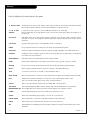
1. Read Instructions
All the safety and operating instructions should be read
before the product is operated.
2. Follow Instructions
All operating and use instructions should be followed.
3. Retain Instructions
The safety and operating instructions should be retained
for future reference.
4. Heed Warnings
All warnings on the product and in the operating instruc-
tions should be adhered to.
5. Cleaning
Unplug this product from the wall outlet before cleaning.
Do not use liquid cleaners or aerosol cleaners. Use a damp
cloth for cleaning.
6. Water and Moisture
Do not use this product near water for example, near a
bath tub, wash bowl, kitchen sink, or laundry tub, in a
wet basement, or near a swimming pool.
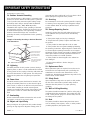
7. Accessories, Carts, and Stands
Do not place this product on a slippery or tilted surface,
or on an unstable cart, stand, tripod, bracket, or table.
The product may slide or fall, causing serious injury to a
child or adult, and serious damage to the product. Use
only with a cart, stand, tripod, bracket, or table recom-
mended by the manufacturer, or sold with the product.
Any mounting of the product should follow the manufac-
turer’s instructions, and should use a mounting accessory
recommended by the manufacturer.
8. Transporting Product
A product and cart combination should be moved with
care. Quick stops, excessive force, and uneven surfaces
may cause the product and cart combination to overturn.
9. Attachments
Do not use attachments not recommended by the product
manufacturer as they may cause hazards.
10. Ventilation
Slots and openings in the cabinet are provided for
ventilation and to ensure reliable operation of the product
and to protect it from overheating, and these openings
must not be blocked or covered. The openings should
never be blocked by placing the product on a bed, sofa,
rug, or other similar surface. This product should not be
placed in a built-in installation such as a bookcase or rack
unless proper ventilation is provided or the manufacturer’s
instructions have been adhered to.
11. Power Sources
This product should be operated only from the type of
power source indicated on the marking label. If you are
not sure of the type of power supply, consult your product
dealer or local power company. For products intended to
operate from battery power, or other sources, refer to the
operating instructions.
12. Power-Cord Polarization
This product is equipped with a polarized alternating -
current power plug (a plug having one blade wider than
the other). This plug will fit into the power outlet only
one way. This is a safety feature. If you are unable to
insert the plug fully into the outlet, try reversing the
plug. If the plug should still fail to fit, contact your
electrician to replace your obsolete outlet. Do not defeat
the safety purpose of the polarized plug.
13. Power-Cord Protection
Power-supply cords should be routed so that they are not
likely to be walked on or pinched by items placed upon or
against them, paying particular attention to cords at
plugs, convenience receptacles, and the point where they
exit from the product.
PAGE 3
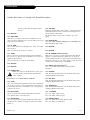
IMPORTANT SAFETY INSTRUCTIONS
PORTABLE CART WARNING
(Continued on next page)
3706 2-WR-POLZ

(Continued from previous page)
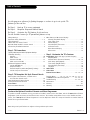
14. Outdoor Antenna Grounding
If an outside antenna or cable system is connected to the
product, be sure the antenna or cable system is grounded
so as to provide some protection against voltage surges
and built-up static charges. Article 810 of the National
Electrical Code (U.S.A.), ANSI/ NFPA 70 provides
information with regard to proper grounding of the mast
and supporting structure, grounding of the lead-in wire to
an antenna discharge unit, size of grounding conductors,
location of antenna-discharge unit, connection to
grounding electrodes, and requirements for the grounding
electrode.
15. Lightning
For added protection for this product (receiver) during a
lightning storm, or when it is left unattended and unused
for long periods of time, unplug it from the wall outlet and
disconnect the antenna or cable system. This will prevent
damage to the product due to lightning and power-line
surges.
16. Power Lines
An outside antenna system should not be located in the
vicinity of overhead power lines or other electric light or
power circuits, or where it can fall into such power lines or
circuits. When installing an outside antenna system,
extreme care should be taken to keep from touching such
power lines or circuits as contact with them might be
fatal.
17. Overloading
Do not overload wall outlets and extension cords as this
can result in a risk of fire or electric shock.
18. Object and Liquid Entry
Never push objects of any kind into this product through
openings as they may touch dangerous voltage points or
short-out parts that could result in a fire or electric shock.
Never spill liquid of any kind on the product.
19. Servicing
Do not attempt to service this product yourself as opening
or removing covers may expose you to dangerous voltage
or other hazards. Refer all servicing to qualified service
personnel.
20. Damage Requiring Service
Unplug this product from the wall outlet and refer servic-
ing to qualified service personnel under the following
conditions:
a. If the power-supply cord or plug is damaged.
b. If liquid has been spilled, or objects have fallen into
the product.
c. If the product has been exposed to rain or water.
d. If the product does not operate normally by following
the operating instructions. Adjust only those controls that
are covered by the operating instructions as an improper
adjustment of other controls may result in damage and will
often require extensive work by a qualified technician to
restore the product to its normal operation.
e. If the product has been dropped or the cabinet has
been damaged.
f. If the product exhibits a distinct change in
performance.
21. Replacement Parts
When replacement parts are required, be sure the service
technician has used replacement parts specified by the
manufacturer or have the same characteristics as the
original part. Unauthorized substitutions may result in fire,
electric shock, or other hazards.
22. Safety Check
Upon completion of any service or repairs to this product,
ask the service technician to perform safety checks to
determine that the product is in proper operating
condition.
23. Wall or Ceiling Mounting
The product should be mounted to a wall or ceiling only as
recommended by the manufacturer. The product may slide
or fall, causing serious injury to a child or adult, and seri-
ous damage to the product.
24. Heat
The product should be situated away from heat sources
such as radiators, heat registers, stoves, or other products
(including amplifiers) that produce heat.
PAGE 4
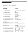
IMPORTANT SAFETY INSTRUCTIONS
3706 2-WR-POLZ
Antenna Lead in Wire
Antenna Discharge Unit
(NEC Section 810-20)
Grounding Conductor
(NEC Section 810-21)
Ground Clamps
Power Service Grounding
Electrode System (NEC
Art 250, Part H)
Ground Clamp
Electric Service
Equipment
NEC - National Electrical Code
Example of Grounding According to National Electrical
Code Instructions

206-3858
PAGE 5
Table of Contents
Use this page as a reference for finding the pages or sections to go to set up the TV’s
features for the end user
Do Step 1. Hook up TV to source equipment
Do Step 2. Reception Setup and Channel Search
Do Step 3. Customize the TVs features for the end user
See the Installer’s menus for TV operational features set up
Safety Warnings . . . . . . . . . . . . . . . . . . . . . . . . . . . . 2
Important Safety Information . . . . . . . . . . . . . . . . 3 - 4
Table of Contents . . . . . . . . . . . . . . . . . . . . . . . . . . . 5
SC652Z End User remote control . . . . . . . . . . . . . . . . 6
Optional LP702 Installer’s remote control . . . . . . . . . . . 7
Connections/Installation Overview . . . . . . . . . . . . . . . 8
Step 1. TV Connections
TV/VCR/Cable Box/and other Equipment Hookup
TV Hookup Directory . . . . . . . . . . . . . . . . . . . . . . . . . 9
Antenna . . . . . . . . . . . . . . . . . . . . . . . . . . . . . . 10
Cable service . . . . . . . . . . . . . . . . . . . . . . . . . . . 11
Antenna with VCR . . . . . . . . . . . . . . . . . . . . . . . 12
Cable service with VCR . . . . . . . . . . . . . . . . . . . . 13
Additional Equipment Hookup
S-Video VCR/DVD etc. . . . . . . . . . . . . . . . . . . . . . 14
Component Video . . . . . . . . . . . . . . . . . . . . . . . 15
External Amplifier (Audio Out [Matrix] hookup) . . . . 16
S-Video Loop-out connections . . . . . . . . . . . . . . . 17
Step 2. TV Reception Set Up & Channel Search
Auto Program: Select Antenna, or Cable service
and start the channel search . . . . . . . . . . . . . . . . 18
Front Panel Controls/Source Inputs . . . . . . . . . . . . . . 19
Picture/Sound Source Selection . . . . . . . . . . . . . . . . 20
Source Menu . . . . . . . . . . . . . . . . . . . . . . . . . . . . 21
On-Screen Menus Overview . . . . . . . . . . . . . . . . . . . . 22
Other Menus and On-Screen Displays
Channel/Time/Audio Display . . . . . . . . . . . . . . . . . 23
Sleep Timer menu . . . . . . . . . . . . . . . . . . . . . . . . 23
Volume Display . . . . . . . . . . . . . . . . . . . . . . . . . 23
Closed Captions/Text menu . . . . . . . . . . . . . . . . . . 23
Ch Preview menu . . . . . . . . . . . . . . . . . . . . . . . . 23
Ghost Channel Display . . . . . . . . . . . . . . . . . . . . 23
Alarm menu . . . . . . . . . . . . . . . . . . . . . . . . . . . 23
Step 3. Customize the TV’s Features
Setup Menu (Starts with page 18, Auto Program)
Add/Del/Blank . . . . . . . . . . . . . . . . . . . . . . . . . . 24
Channel Labels (Preset and Custom) . . . . . . . . 25 - 26
Clock Setup (Auto/Manual) . . . . . . . . . . . . . . . . . . 27
Timer Setup (On/Off Timers) . . . . . . . . . . . . . . . . 28
Closed Captions/Text Setup . . . . . . . . . . . . . . . . . 29
Language . . . . . . . . . . . . . . . . . . . . . . . . . . . . . 30
Audio Menu . . . . . . . . . . . . . . . . . . . . . . . . . . . . . 31
Video Menu . . . . . . . . . . . . . . . . . . . . . . . . . . . . . 32
Parental Control Menu . . . . . . . . . . . . . . . . 33 - 34 - 35
Installer Menus . . . . 36 - 37 - 38 - 39 - 40 - 41 - 42 - 43
LT2000 Quickset II Clone Programmer . . . . . . 44 - 45 - 46
Troubleshooting . . . . . . . . . . . . . . . . . . . . 47 - 48 - 49
Maintenance . . . . . . . . . . . . . . . . . . . . . . . . . . . . . 50
Glossary . . . . . . . . . . . . . . . . . . . . . . . . . . . . . . . . 51
Warranty . . . . . . . . . . . . . . . . . . . . . . . . . . Back Cover
Note: Design and specifications are subject to change without prior notice.
Purchase the Optional Installer’s Remote and Clone Programmer
To perform a normal installation set up, you need an installer’s remote such as the LP702, and the LT2000 Quickset II Clone
Programmer—both are shown and described in later sections. The installer remote allows access to the Installer and User
menus. The LT2000 Quickset II Clone Programmer is used to duplicate a Zenith TV’s setup and install it on another identical
Zenith TV. See your Zenith Dealer.

206-3888
PAGE 6
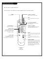
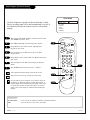
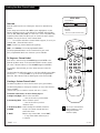
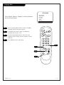
SC652Z User Remote Control
TIMER ALARM
CH PREVIEW
ENTER
1
2
3
4
5
6
7
8
9
0
POWER
FLSHBK
MUTE
VOL
UME
CHANNEL
CC
remote control part number
SC652Z
124-213-18
(LG 6710V00108A)
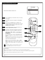
FLASHBK (FLASHBACK)
Returns to the last channel viewed.
POWER
Turns TV On or Off
.
CHANNEL (UP/DOWN)
Scroll through available channels, and the
Video Channel (Audio/Video source).
MUTE
Turns sound Off and On, while the picture
remains.
ENTER
Press to view the Channel/Time/Audio display
or to remove any on-screen display or menu.
NUMBER KEYPAD
Select channels directly; enter
channel numbers and press ENTER
to go to new channel
. Use to key-
in numbers on menus.
(SLEEP) TIMER
Press repeatedly to choose a TV
turn-off time up to 4-hours.
Use to set AM/PM on the Alarm menu.
VOLUME DOWN/UP
Adjusts the sound level.
CHANNEL PREVIEW
Displays the available TV channels, gives the
hotel guest access to the Aux Channel and (if
active) the Guest Parental Control menu. Aux
Channel allows the guest to select the
Video/Audio inputs. (Use the Video/Audio
jacks on the back of the TV as the source of
the picture and sound.)
CC (CLOSED CAPTIONING)
Press to access closed captions options.
Press ENTER to exit.
A list of the keys on the SC652Z user’s remote supplied with the TV and their function
ALARM
Press to display menu, follow on-screen
instructions to set a time for the TV to turn
itself on.
Note: This remote is supplied with the TV.

206-3740
PAGE 7
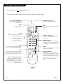
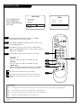
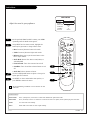
LP702 Optional Installer’s Remote
TIMER
CH PREVIEW
ENTER
1
2
3
4
5
6
7
8
9
0
POWER
FLSHBK
MUTE
VOL
UME
CHANNEL
TV/FM
CC
MENU
ALARM
ADJ
ADJ
SELECT
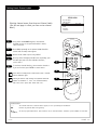
FLASHBK (FLASHBACK)
Returns to the last channel viewed.
POWER
Turns TV On and Off
.
CHANNEL (UP/DOWN)
Selects next available channel and the
video channel.
MUTE
Turns sound Off and On, while the picture
remains.
ENTER
Press to view the Channel/Time display or
to remove any on-screen display or menu.
remote control part number
LP702
124-213-04
TIMER
Press repeatedly to select preset TV turn-
off time from 10 minutes up to 4-hours.
Sets AM or PM in the Clock/Alarm menus.
VOLUME (DOWN/UP)
Adjusts the sound level.
CC (CLOSED CAPTIONING)
Direct access to closed captions.
Press ENTER to exit.
A list of the keys on the optional LP702 installer’s remote and what they do
ALARM
Press to go to the Alarm menu. Set a time
for the TV to turn itself on.
MENU/SELECT/ADJ (ADJUST)
Adjusts on-screen menus and options.
Press MENU repeatedly to scroll through
menus. Use SELECT to choose an option
and ADJ (adjust) Left/Right to change
the selected option.
CHANNEL PREVIEW
Gives installer access to the Guest’s
menus. Displays the available TV channels
and hotel guest’s Parental Control menu
(if active). Selects the Video source. (Use
the Audio/Video jacks on the back of the
TV as the source of the picture and
sound.)
TV/FM
Selects TV or Radio operation on TVs
equipped with FM radio.
NUMBER KEYPAD
Used to key-in numbers and select chan-
nels directly; key-in channel numbers and
press ENTER to go to the new channel
.
Note: This remote is NO
T supplied with the TV.

206-3686
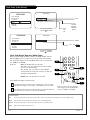
PAGE 8
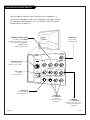
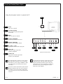
Typical
TV Back
S-Video In
M.P.I.
R Audio In L
S-Video Out
Antenna
Cable
Component Video Input
R Audio In L
R Audio L
Video In
Y
Pr
Pb
Matrix Out
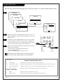
S-VIDEO IN
R-L AUDIO IN
Connect
S-Video equipment to
these jacks.
ANTENNA/CABLE
Use to hookup your
antenna or cable system.
M.P.I. PORT
Use with
Clone Programmer.
COMPONENT VIDEO INPUT
Pr, Pb, Y, R-L AUDIO
Connection for standard component
video equipment or DVD player.
DVD Player, 480i
SDTV Set top Box, 480i
VIDEO IN
R - L AUDIO IN
Use these input jacks to con-
nect external audio/video
equipment.
Use this page for reference when connecting source equipment. To
hookup source equipment, refer to the next page; shows pages to go to
for equipment hookup options. Also, see the front connections panel
hookup options on page 19.
Connections/Installation Overview
MATRIX OUT
Use to hookup
external speaker.
S-VIDEO OUT
Connect to external
S-Video device input.

206-3686
PAGE 9
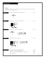
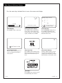
Hookup Directory
If you are using an antenna and no other equipment, go to . . . . . . . . . . . . . . . . . . page 10
If you have cable service and no other equipment, go to . . . . . . . . . . . . . . . . . . . . page 11
If you are using an antenna and have a VCR, go to . . . . . . . . . . . . . . . . . . . . . . . page 12
If you have cable service and a VCR, go to . . . . . . . . . . . . . . . . . . . . . . . . . . . . . . page 13
If you want to connect an S-Video VCR/DVD Player etc. . . . . . . . . . . . . . . . . . . . . page 14
IMPORTANT!!
Use this page to decide where you need to begin your set up. First, find the line below that best describes what
you want to do, then go to that page number.
Cable TV
Wall Jack
Cable Box
In
Out
Cable TV
Wall Jack
Cable Box
In
Out
Antenna only
Cable only
Antenna with VCR
Cable and VCR
S-Video/Speaker
If you want to hook up a component video device . . . . . . . . . . . . . . . . . . . . . . . . page 15
Send the TV sound to an external audio system or monaural speaker . . . . . . . . . . . . . page 16
S-Video loopout setup . . . . . . . . . . . . . . . . . . . . . . . . . . . . . . . . . . . . . . . . . . . page 17

PAGE 10
206-3686
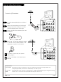
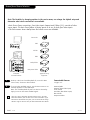
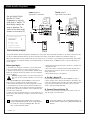
Hook Up An Over-The-Air Antenna
Mini glossary
75 OHM RF CABLE The wire that comes from an off-air antenna or cable service provider. Each end looks like a hex shaped nut with a wire
sticking through the middle, and it screws onto the threaded jack on the back of your TV.
A small device that connects a two-wire 300 ohm antenna to a 75 ohm RF jack (Antenna/Cable). They are usually about an inch long
with two screws on one end and a round opening with a wire sticking out on the other end.
Connect an off-air antenna
If you have a 75 ohm RF cable, then you don’t
need any adapters!
A 300 to 75 ohm adapter is not included with the
Zenith TV.
300 TO 75 OHM
ADAPTER
Typical
TV Back
S-Video In
M.P.I.
R Audio In L
S-Video Out
Antenna
Cable
Component Video Input
R Audio In L
R Audio L
Video In
Y
Pr
Pb
Matrix Out
Flat Wire
(300 ohm)
Antenna
300/75 ohm
Adapter
Typical
TV Back
S-Video In
M.P.I.
R Audio In L
S-Video Out
Antenna
Cable
Component Video Input
R Audio In L
R Audio L
Video In
Y
Pr
Pb
Matrix Out
RF Coaxial Wire
(75ohm)
Antenna
Locate the Antenna/Cable jack on the back of
the TV.
Connect the antenna that runs from the wall
directly to this jack, according to one of the
connection diagrams shown to the right.
Remove the back of the remote and put in two
AA batteries.
Plug in your TV. This TV is designed to operate
on standard current, 120-volt 60 Hertz AC. Do
not attempt to operate it on DC Current.
Back of
Remote
120 Volt
60 Hz AC
1
2
3
4

PAGE 11
206-3686
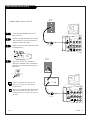
Hook Up Cable Service (CATV)
If you’re using a cable box, tune the TV to
channel 3 or 4 and use your cable box to
change channels.
If you’re using a cable box, Auto Program might
only find the channel your cable service is on
(usually channel 3 or 4). Don’t worry, that’s all
you need!
Typical
TV Back
S-Video In
M.P.I.
R Audio In L
S-Video Out
Antenna
Cable
Component Video Input
R Audio In L
R Audio L
Video In
Y
Pr
Pb
Matrix Out
Cable TV
Wall Jack
RF Coaxial Wire
(75ohm)
Typical
TV Back
S-Video In
M.P.I.
R Audio In L
S-Video Out
Antenna
Cable
Component Video Input
R Audio In L
R Audio L
Video In
Y
Pr
Pb
Matrix Out
Cable TV
Wall Jack
Cable Box
In
Out
RF Coaxial Wire
(75ohm)
3 4
output
switch
Locate the Antenna/Cable jack on the
back of the TV.
Connect the CATV cable that runs from the
wall according to one of the connection
diagrams shown to the right.
Remove the back of the remote and install
two AA batteries.
Plug in the TV. The TV is designed to
operate on standard current, 120-volt 60
Hertz AC. Do not attempt to operate it on
DC Current.
120 Volt
60 Hz AC
1
2
3
4
Connect cable service to the TV
Back of
Remote

PAGE 12
206-3686
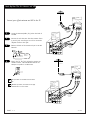
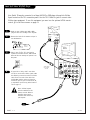
Hook Up Over-The-Air Antenna and VCR
Connect your off-air antenna and VCR to the TV
No A/V cables are included with the Zenith
TV.
Without A/V cables, most VCRs will not play
videocassettes in stereo sound.
Typical
TV Back
S-Video In
M.P.I.
R Audio In L
S-Video Out
Antenna
Cable
Component Video Input
R Audio In L
R Audio L
Video In
Y
Pr
Pb
Matrix Out
In
Out
Audio
Video
3 4
VCR Back
VCR Back AV Panel
output
switch
Flat Wire
(300 ohm)
Antenna
300/75 ohm
Adapter
A/V cables
not included
with TV
Typical
TV Back
S-Video In
M.P.I.
R Audio In L
S-Video Out
Antenna
Cable
Component Video Input
R Audio In L
R Audio L
Video In
Y
Pr
Pb
Matrix Out
In
Out
Audio
Video
3 4
VCR Back
VCR Back AV Panel
output
switch
A/V cables
not included
with TV
RF Coaxial Wire
(75ohm)
Antenna
Locate the Antenna/Cable (In) jack on the back of
the VCR.
Connect the wire that runs from the antenna direct-
ly to this jack, according to one of the connection
diagrams shown to the right.
Remove the back of the remote and put in two AA
batteries.
Plug in the TV. The TV is designed to operate on
standard current, 120-volt 60 Hertz AC. Do not
attempt to operate it on DC Current.
120 Volt
60 Hz AC
1
2
3
4
Back of
Remote

PAGE 13
206-3686
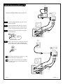
Hook Up Cable Service (CATV) and VCR
Connect a VCR and Cable service to the TV
Tune the VCR and television to channel 3 or 4 and
use the cable box to change channels.
No A/V cables are included with your TV. Without
A/V cables, most VCRs will not play videocassettes
in stereo sound.
Typical
TV Back
S-Video In
M.P.I.
R Audio In L
S-Video Out
Antenna
Cable
Component Video Input
R Audio In L
R Audio L
Video In
Y
Pr
Pb
Matrix Out
In
Out
Audio
Video
3 4
VCR Back
VCR Back AV Panel
output
switch
A/V cables
not included
with TV
Cable TV
Wall Jack
RF Coaxial Wire
(75ohm)
Typical
TV Back
S-Video In
M.P.I.
R Audio In L
S-Video Out
Antenna
Cable
Component Video Input
R Audio In L
R Audio L
Video In
Y
Pr
Pb
Matrix Out
In
Out
Audio
Video
3 4
VCR Back
VCR Back AV Panel
output
switch
A/V cables
not included
with TV
Cable TV
Wall Jack
Cable Box
In
Out
RF Coaxial Wire
(75ohm)
3 4
output
switch
Locate the Antenna/Cable (In) jack on the
back of the VCR.
Connect the CATV cable that runs from the
wall directly to this jack, according to one
of the connection diagrams shown at right.
Remove the back of the remote and install
two AA batteries.
Plug in the TV. The TV is designed to operate
on standard current, 120-volt 60 Hertz AC.
Do not attempt to operate it on DC Current.
120 Volt
60 Hz AC
1
2
3
4
Back of
Remote

PAGE 14
206-3686
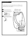
Hook Up S-Video VCR/DVD Player
S-Video cables
not included
with TV
Audio Out
S-Video
Out
3 4
VCR Back
VCR Back AV Panel
Output
Switch
R L
Typical
TV Back
S-Video In
M.P.I.
R Audio In L
S-Video Out
Antenna
Cable
Component Video Input
R Audio In L
R Audio L
Video In
Y
Pr
Pb
Matrix Out
Your Zenith TV may be connected to a Super-VHS VCR or DVD player through the S-Video
Input located on the TV’s connection panel. Use the TV’s S-Video In jack to connect other
S-Video type equipment. To use this equipment you must use the optional LP702 remote
control, go to the Source menu on page 21.
Hook up your S-Video type VCR or DVD
player to the TV according to the diagram.
Remove the back of the remote and put in
two AA batteries.
Plug in your TV. The TV is designed to
operate on standard current, 120-volt 60
Hertz AC. Do not attempt to operate it on
DC power.
If you wish to “daisy chain” more than
one TV to receive the S-Video signal, make
the following connections with an S-Video
cable. Insert one end of the cable into
S-Video Out and the other end into the
S-Video In jack on your second Zenith TV,
or equivalent input for any other brand of
TV. See page 17.
1
2
3
4
4
Back of
Remote
120 Volt
60 Hz AC
Note: S-Video loopout
must be enabled for this
feature to work. Refer to
Installers menu pages,
Installer menu item 33-I,
Y/C Loopout.

206-3858
PAGE 15
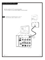
Hook Up Component Video
Typical
TV Back
S-Video In
M.P.I.
R Audio In L
S-Video Out
Antenna
Cable
Component Video Input
R Audio In L
R Audio L
Video In
Y
Pr
Pb
Matrix Out
DVD Player with
Component Video
COMPONENT VIDEO OUT
Y
Pr
Pb
R
L
S-VIDEO OUT
VIDEO
R-AUDIO
L-/MONO
The Zenith TV may be connected to a Component Video device like a DVD player or other
component video source. To use this equipment you must use the optional LP702 remote
control, refer to the Source menu on page 21.
Hook up your component video device
according to the diagram at the right.
Remove the back of the remote and install
two high-quality alkaline AA batteries.
Plug in your TV. The TV is designed to
operate on standard current, 120-volt 60
Hertz AC. Do not attempt to operate it on
DC power.
1
2
3
Back of
Remote
120 Volt
60 Hz AC

PAGE 16
206-3686
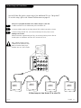
Send the sound from the TV to an external speaker.
To use this hookup, see your external amplifier instruction manual.
Audio Output: Use the Matrix Out jack to connect an
external monaural speaker or amplifier to the TV.
1
External Monaural Speaker Hookup
Typical
TV Back
S-Video In
M.P.I.
R Audio In L
S-Video Out
Antenna
Cable
Component Video Input
R Audio In L
R Audio L
Video In
Y
Pr
Pb
Matrix Out
A/V cables
not included
with TV
Audio In
Speaker Back

PAGE 17
206-3740
S-Video Loop-out Connections
ABC
ABC
ABC
ABC
Typical
TV Back
S-Video In
M.P.I.
R Audio In L
S-Video Out
Antenna
Cable
Component Video Input
R Audio In L
R Audio L
Video In
Y
Pr
Pb
Matrix Out
Setup for Looping-Out the Master TV’s S-Video Image to other TVs
1. Make connections to the S-Video Out jack on the Master TV.
2. Connect S-Video cables to the daisy-chained TV’s S-Video input jacks as shown.
3. On the “Daisy-chained” TVs, select the S-Video Input for the picture source.
Viewing Sources Note:
Follow instructions supplied with your TV(s) for selecting viewing sources. Picture
should appear on the Master and other TVs connected in series.
S-Video Loop-out from Master TV to other TVs
Use the S-Video Out jack to connect up to four additional TVs in a “daisy-chain”.
To use this setup, refer to the Channel Preview menu on page 23.
1
2
3
Note: S-Video loopout must be
enabled for this feature to work.
Refer to Installer menu pages,
Installer item 33-I, Y/C Loopout.

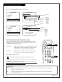
PAGE 18
206-3686
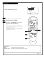
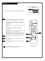
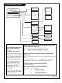
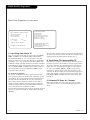
Auto Program (Channel Search)
Use Auto Program to specify over-the-air Antenna or Cable
Service incoming signal source and automatically store all of
the channels found by the channel search in non-volatile
memory
With the optional LP702 Installer’s remote control in hand,
press POWER to turn the TV on.
Press MENU repeatedly until the Setup menu appears.
Using SELECT on the remote control, highlight Auto
Program on the screen.
Press the Right or Left ADJ arrow to go to the Auto
Program menu.
Using SELECT, choose either Cable TV or Off-Air Antenna on
your screen.
Press the Right or Left ADJ arrow to begin the Channel
Search.
Press ENTER when the channel search is complete.
1
2
3
4
5
6
7
AUTO PROGRAM
ADD/DEL/BLNK
CH. LABELS
CLOCK SET
TIMER
CAPTIONS
LANGUAGE
TO PROGRAM
SETUP MENU
Mini glossary
OFF-AIR-ANTENNA If only over-the-air channels are available, select Off-Air-Antenna.
CABLE If you subscribe to a cable service, select Cable.
Auto Program finds channels being received by the TV tuner.
Cable will not work unless you subscribe to a cable service.
Once the channel search is complete, use the features on the fol-
lowing pages to: Add/delete channels, Include channel labels, so
that they appear on the channel/time/audio display. Choose from
the preset label selections or make custom labels. Use your own
names to more easily identify the station/network providing the
program.
TIMER
CH PREVIEW
ENTER
1
2
3
4
5
6
7
8
9
0
POWER
FLSHBK
MUTE
VOL
UME
CHANNEL
TV/FM
CC
MENU
ALARM
ADJ
ADJ
SELECT
2
7
3/5
4/6
1

PAGE 19
206-3888
Front Panel Controls/Source Inputs
power
Typical TV
Front Panel
vol
ch
mute
R-audio-L
video
S-video
CC
Power
Turns TV on and off.
CC (Captions/Text)
Turns selected caption/text option
on and off.
Mute
Turns TV sound on and off.
Volume (Left/Right)
Decreases/increases sound level.
Channel (Down/Up)
Chooses next available channel.
R - Audio - L (In)
Right/Left Channel audio input jacks.
Video (In)
Input for a video signal from
auxiliary equipment.
S-Video (In)
Input for an S-Video signal from
S-Video (Y-C) equipment.
Using the front panel controls to operate the TV
A
B
C
D
The front Video jacks are Auto Sense source connec-
tions. With cables connected, the TV will automati-
cally change its source setting to CAMPORT, or FRNT
Y/C (Front S-Video) as indicated on the channel-
time display.
If you have a device connected to the front Video or
S-Video jack and the Auto sense source connection
is turned on, you will not be able to change chan-
nels using the TV tuner until you have disconnected
the device.
Typical Front Panel Controls
D
C
F
G
E
F
G
H
The front Video input jack has a priority over the front
S-Video input jack. If you have cables connected to
both the front Video jack and the front S-Video jack
(and the Auto sense source connection is turned on in
the Installer menu), only the image from the front
Video input will be displayed.
E
B
A
H

PAGE 20
206-3740
Picture/Sound Source Selection
AUDIO/S-VIDEO OUT
R-AUDIO-L
OUTPUT
S-VIDEO
R-AUDIO-L
AUDIO/VIDEO OUT
R-AUDIO-L
AUDIO/VIDEO OUT
VIDEO
R-AUDIO-L
COMPONENT VIDEO
R -AUDIO-L
Video In
R-Audio - L
Camcorder
VCR
S-Video
Audio/Video
DVD
Component Video
S-VIDEO
S-Video
Typical
TV Back
S-Video In
M.P.I.
R Audio In L
S-Video Out
Antenna
Cable
Component Video Input
R Audio In L
R Audio L
Video In
Y
Pr
Pb
Matrix Out
Pb
Y Pr
VIDEO
Hook up a device to front Video/Audio In, to use this Auto
Sense source, disconnect when finished.
To access other available sources, use the Source menu or use
Channel Up/Down to select AUX input.
Note: The rear Video/Audio In jacks can also be selected by
keying in 999 on the remote number keypad.
Note: The Installer, by changing options in the service menu, can change the default setup and
determine what source connections are available.
• Auto Source Sense connections, front video inputs Camport and S-Video (Y-C), override all other
source inputs. The Auto Sense feature is factory preset to be on; for both front video inputs.
• The Source menu shows what picture and sound sources are available.
1
2
Auto Sense source connections override all other sources. The front
Video and S-Video In jacks are Auto Sense source connections. If you
have devices connected to these jacks, you will not be able to change
channels using the TV tuner until you have disconnected those devices.
Typical Accessory
Equipment
Front/Rear
Connection Panels
Connectable Sources
See pages 9-17
Antenna/Cable
Camport (Front Video input)
Front S-Video
Aux Video (Rear Video inputs)
Rear S-Video
Component Video
La pagina sta caricando ...
La pagina sta caricando ...
La pagina sta caricando ...
La pagina sta caricando ...
La pagina sta caricando ...
La pagina sta caricando ...
La pagina sta caricando ...
La pagina sta caricando ...
La pagina sta caricando ...
La pagina sta caricando ...
La pagina sta caricando ...
La pagina sta caricando ...
La pagina sta caricando ...
La pagina sta caricando ...
La pagina sta caricando ...
La pagina sta caricando ...
La pagina sta caricando ...
La pagina sta caricando ...
La pagina sta caricando ...
La pagina sta caricando ...
La pagina sta caricando ...
La pagina sta caricando ...
La pagina sta caricando ...
La pagina sta caricando ...
La pagina sta caricando ...
La pagina sta caricando ...
La pagina sta caricando ...
La pagina sta caricando ...
La pagina sta caricando ...
La pagina sta caricando ...
La pagina sta caricando ...
La pagina sta caricando ...
-
 1
1
-
 2
2
-
 3
3
-
 4
4
-
 5
5
-
 6
6
-
 7
7
-
 8
8
-
 9
9
-
 10
10
-
 11
11
-
 12
12
-
 13
13
-
 14
14
-
 15
15
-
 16
16
-
 17
17
-
 18
18
-
 19
19
-
 20
20
-
 21
21
-
 22
22
-
 23
23
-
 24
24
-
 25
25
-
 26
26
-
 27
27
-
 28
28
-
 29
29
-
 30
30
-
 31
31
-
 32
32
-
 33
33
-
 34
34
-
 35
35
-
 36
36
-
 37
37
-
 38
38
-
 39
39
-
 40
40
-
 41
41
-
 42
42
-
 43
43
-
 44
44
-
 45
45
-
 46
46
-
 47
47
-
 48
48
-
 49
49
-
 50
50
-
 51
51
-
 52
52


Zenith H27F56DT Guida d'installazione
- Categoria
- TV LCD
- Tipo
- Guida d'installazione
in altre lingue
- English: Zenith H27F56DT Installation guide
Documenti correlati
-
Zenith H27E55DT Istruzioni per l'uso
-
-
-
-
-
-
-
-
-
