Master B35-150CED DV 4100.118 E19R12 Manuale del proprietario
- Categoria
- Riscaldatori di spazio
- Tipo
- Manuale del proprietario

B 35CED DV - B 70CED DV
B 100CED DV - B 150CED DV
USER AND MAINTENANCE BOOK
LIBRETTO USO E MANUTENZIONE

FIGURES - FIGURE

FIGURES - FIGURE

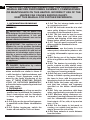
IMPORTANT: READ AND UNDERSTAND THIS OPERATIONAL
MANUAL BEFORE PERFORMING ASSEMBLY, COMMISSIONING
OR MAINTENANCE ON THIS HEATER. INCORRECT USE OF THE
HEATER CAN CAUSES SERIOUS INJURY.
KEEP THIS MANUAL FOR FURTHER REFERENCE.
1. INFORMATION REGARDING
SAFETY
WARNINGS
IMPORTANT: This air heater has
been designed for mobile and temporary
professional applications. It has not
been designed for domestic use nor for
thermal comfort of human.
IMPORTANT: This appliance is not
intended for use by persons (including
children) with reduced physical, senso-
ry and mental capacities or with lack of
experience or knowledge unless super-
vised by a person responsible for their
safety. Children must be supervised to
make sure they neither do nor play with
the appliance.
DANGER: Suocation by carbon
monoxide can be fatal.
The rst symptoms of suocation by
carbon monoxide are similar to those of
u with headache, light-headedness and/
or nausea. These symptoms could be
caused by the faulty functioning of the
heater. IF THESE SYMPTOMS SHOULD
OCCUR, DO OUTDOORS IMMEDIATELY
and have the heater repaired by a technical
after-sales centre.
1.1 TOPPING-UP:
►1.1.1. Sta in charge of top-up must be
qualied and understand the manufac
-
turer’s instructions and the Standards
in force regarding safe top-up of the
heaters.
►1.1.2. Only use the type of fuel express
-
ly specied on the heater identication
plate.
►1.1.3. Before topping-up, switch the
heater o and wait for it to cool down.
►1.1.4. The fuel storage tanks must be
in a separate structure.
►1.1.5. All fuel tanks must be at a mini
-
mum safety distance from the heater,
according to the Standards in force.
►1.1.6. The fuel must be kept in rooms
where the oor does not allow pen-
etration and dripping of the same onto
ames below, which can cause ignition.
►1.1.7. The fuel must be stored in com
-
pliance with the Standard in force.
1.2 SAFETY:
►1.2.1. Never use the heater in rooms
where petrol, solvents for paints or oth-
er highly inammable vapours are pre-
sent.
►1.2.2. During use of the heater, follow
all local regulations and the Standard in
force.
►1.2.3. The heaters in proximity of tar-
paulin, curtains or other similar cover-
ing materials, must be situated at a safe
distance from the same. It is advised to
use re-proof covering material.
►1.2.4. Only use in well-ventilated areas.
Set-up a suitable opening according to
the Laws in force, with the purpose of
introducing fresh air from outdoors.
►1.2.5. Power the heater only with cur-
rent that has voltage and frequency
specied on the heater identication
plate.
►1.2.6. Only use extensions with three
wires, appropriately connected to earth.
►1.2.7. Minimum safety distances rec-
ommended, running between the heater
and the inammable substances are:
front output = 2.5 m; side, at top and on
rear = 1.5 m.
►1.2.8. Put the heater in hot mode or
running, on a stable level surface, in a
way to prevent the risk of re.
►1.2.9. Keep animals at a safe distance
from the heater.
en
it
de
es
fr
nl
pt
da
no
sv
pl
ru
cs
hu
sl
tr
hr
lt
lv
et
ro
sk
bg
uk
bs
el
zh

►1.2.10. Disconnect the heater from the
mains socket when not in use.
►1.2.11. When it is controlled by a
thermostat, the heater can switch on at
any time.
►1.2.12. Never use the heater in
frequently inhabited rooms, or in the
bedroom.
►1.2.13. Never block the air vent (rear
side) or the air outlet (front side) of the
heater.
►1.2.14. When the heater is hot or
connected to the mains electricity or
functioning, it must never be moved,
handled, topped-up or subject to any
maintenance interventions.
►1.2.15. Do not duct the air entering or
exiting the heater.
►1.2.16. Keep the hot parts of the
heater at an adequate distance from
inammable or termolabile materials
(including the power supply cable).
►1.2.17. If the power supply cable is
damaged, it must be replaced by the
technical after-sales centre, in order to
prevent all risks.
2. UNPACKING
►I°. Remove all packaging materials used to
wrap and deliver the heater and dispose of
them in compliance with the Standards in
force.
►II°. Extract all articles from the packaging.
►III°. Control for any damage undergone
during transport. If the heater appears
damaged, inform the dealer, where the
purchase was made, immediately.
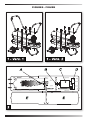
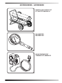
3. ASSEMBLY (29-44 kW)
(SEE FIG. 1) These models have wheels
and handle/s depending on the model. These
components, complete with relative nuts and
bolts, are situated in the heater box.
4. FUEL
WARNING: The heater only functions
with DIESEL or KEROSENE.
Only use diesel or kerosene, to prevent the
risk of re or explosion. Never use petrol,
naphtha, solvents for paints, alcohol or other
highly inammable fuels.
Use non-toxic anti-freeze additives in the
case of very low temperatures.
5. FUNCTIONING PRINCIPLES
(SEE FIG. 2)
A. Combustion chamber and heads, B. Fan,
C. Motor, D. Compressor, E. Tank.
The compressor (D) started by the motor
(C) compresses the air, which through the
atomising nozzle, sucks up the fuel from the
tank (E) due to the “VENTURI EFFECT”.
On contact with the igniter, the atomised fuel
ignites inside the combustion chamber (A).
The combustion products are mixed with the
ow of room air generated by the rotation of
the fan (B) and pushed towards the outside of
the heater. A photoresistance, connected to
a circuit board, constantly checks the correct
functioning of the heater, stopping the cycle
in the event of anomalies.
6. FUNCTIONING
WARNING: Thoroughly read the
”INFORMATION REGADRING SAFETY”,
before switching the heater on.
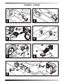
IMPORTANT: Check the position of the
transformer switch (220-240V / 110-
120V). If the voltage set on the appliance
does not correspond to that supplied by
the mains, the voltage must be adapted.
Loosen the two lid screw fasteners,
shift the switch on to the voltage value
supplied and re-mount the lid (SEE FIG.
6).
VERIFY THE CONGRUENCE BETWEEN
POWER TENSION SUPPLY, SETTING OF
DUAL VOLTAGE SWITCH AND TYPE OF
PLUG, BECAUSE IMPROPER USE MAY
CAUSE DAMAGE TO THE HEATER.
6.1 SWITCHING THE HEATER ON:
►I°. Follow all instructions relative to safety.
►II°. Check the presence of fuel in the tank.
►III°. Close the tank cap.
►IV°. Connect the power supply plug to
the mains electricity (SEE VOLTAGE IN
“TECHNICAL DATA TABLE”).
►V°. Take the “ON/OFF” switch to the “ON”
(|) position (SEE FIG. 3-4). The heater
should switch-on within a few seconds. If
en
it
de
es
fr
nl
pt
da
no
sv
pl
ru
cs
hu
sl
tr
hr
lt
lv
et
ro
sk
bg
uk
bs
el
zh

the heater does not start, consult the “12.
TROUBLESHOOTING” paragraph.
►VI°. For the models with room thermostat,
check the position of the knob (SEE FIG.
5-9).
N.B.: IF THE HEATER SHOULD SWITCH-
OFF DUE TO THE LACK OF FUEL, TOP-
UP THE TANK AND RESET THE HEATER
(SEE PAR. 6.2).
6.2 RESETTING THE HEATER:
►I°. Switch the heater o and back on again
(SEE FIG. 3-4).
6.3 SWITCHING THE HEATER OFF:
►I°. Take the “ON/OFF” switch to the “OFF”
(O) position (SEE FIG. 3-4).
7. REGULATING THE
PRESSURE OF THE
COMPRESSOR (SEE FIG. 7)
THE COMPRESSOR PRESSURE MAY
HAVE TO BE RESTORED WITH WEAR OF
THE HEATER.
►I°. Use the “TECHNICAL DATA TABLE”
to identify the correct pressure (Bar - PSI -
kPa) of your heater.
►II°. Remove the screw/cap of the
manometer connection (A).
►III°. Assemble the manometer (not supplied,
see “ACCESSORIES”).
►IV°. Switch the heater on.
►V°. Act on the regulation screw by turning
it clockwise to increase the pressure and
anti-clockwise to decrease it (B).
►VI°. Remove the manometer and restore
the screw/cap (A).
8. CLEANING THE TANK FILTER
(SEE FIG. 8)
DEPENDING ON THE QUALITY OF THE
FUEL THAT IS USED, THE TANK FILTER
MAY HAVE TO BE CLEANED.
►I°. Remove the cap (A) from the tank.
►II°. Extract the lter (B) from the tank.
►III°. Clean the lter (B) with clean fuel,
paying attention not to damage it.
►IV°. Re-mount the lter (B) in the tank.
►V°. Close the cap (A).
9. PRESERVATION AND
TRANSPORT
I ORDER TO KEEP AND/OR TRANSPORTAR
THE HEATER IN THE BEST WAY, STHE
FOLLOWING PROCEDURE MUST BE
FOLLOWED:
►I°. Empty the fuel tank (some models have
a draining cap on the bottom of the tank. In
this case, remove the drain cap and empty
the fuel).
►II°. If the presence of residues is noted,
pour clean fuel into the tank and drain o
again.
►III°. Close the tank cap and/or the draining
cap and dispose of the fuel appropriately
according to the Standards in force.
►IV°. In order to keep the heater in the best
way possible, it must be kept on a level
surface to prevent the escape of fuel and
in a dry place away from any possible
external threats.
10. ROOM THERMOSTAT
CONNECTION (...CED) (optional)
Remove the plug connected to the appliance
and connect the room thermostat (optional)
(SEE FIG. 9). See wiring diagram.
en
it
de
es
fr
nl
pt
da
no
sv
pl
ru
cs
hu
sl
tr
hr
lt
lv
et
ro
sk
bg
uk
bs
el
zh

WARNING: BEFORE PERFORMING ANY MAINTENANCE OR REPAIRS, DISCONNECT THE
POWER SUPPLY CABL FROM THE MAINS AND MAKE SURE THAT THE HEATER IS COLD.
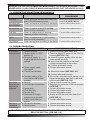
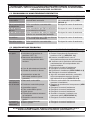
11. PREVENTIVE MAINTENANCE SCHEDULE
COMPONENT MAINTENANCE FREQUENCY MAINTENANCE
PROCEDURE
Fuel tank Empty and rinse the tank with clean fuel
every 150-200 working hours
Empty and rinse the tank with
clean fuel (SEE PAR. 9)
Air outlet and
anti-dist lters
Clean and replace according to necessity Contact after-sales centre
Air inlet lter Clean or replace every 500 working
hours or when necessary
Contact after-sales centre
Fuel lter Clean or replace every 2 working
seasons or when necessary
Contact after-sales centre
Igniter Clean or replace every 1.000 working
hours or when necessary
Contact after-sales centre
Fan blades Clean and replace according to necessity Contact after-sales centre
12. TROUBLESHOOTING
PROBLEM POSSIBLE CAUSE POSSIBLE SOLUTION
The heater
does not start
1. Heater blocked
2. Starter switch in “OFF”
position (0)
3. No power supply or
missing adjustment of the
voltage
4. Power supply cable
interrupted
5. Control card blocked
6. Incorrect setting of the
room thermostat (where
present)
1. Reset the heater (SEE PAR. 6.2)
2. Take the “ON/OFF” switch to the “ON” (|)
position (SEE FIG. 3-4)
3a. Insert the power supply cable into the
mains socket correctly
3b. Verify that the position of the dual-
voltage corresponds to the mains
3c. Contact after-sales centre
4. Contact after-sales centre
5a. Reset the heater (SEE PAR. 6.2)
5b. Contact after-sales centre
6. Act on the room thermostat, taking it to a
higher temperature than that of the work
environment (SEE FIG. 5-9)
The motor
starts but the
ame is not
triggered
1. No fuel
2. Incorrect pump pressure
3. Igniter dirty
4. Fuel lter dirty
5. Nozzle dirty
6. Presence of foreign
substances in the tank
7. Flame control device
broken
1. Top-up fuel and reset the heater
2. Regulate the pressure of the compressor
(SEE PAR. 7)
3. Contact after-sales centre
4. Contact after-sales centre
5. Contact after-sales centre
6. Empty and ll the tank with clean fuel
(SEE PAR. 9)
7. Contact after-sales centre
The fan is
blocked or
turns slowly
1. Pump rotor blocked
2. Motor broken
1. Contact after-sales centre
2. Contact after-sales centre
ATTENTION: ON RE-START, MAKE SURE THE GENRATOR HAS BEEN SET VIA THE
RELATIVE BUTTON. (SEE PAR. 6.2)
en
it
de
es
fr
nl
pt
da
no
sv
pl
ru
cs
hu
sl
tr
hr
lt
lv
et
ro
sk
bg
uk
bs
el
zh

IMPORTANTE: LEGGERE E COMPRENDERE QUESTO MANUALE
OPERATIVO PRIMA DI EFFETTUARE L’ASSEMBLAGGIO,
LA MESSA IN FUNZIONE O LA MANUTENZIONE DI QUESTO
RISCALDATORE. L’USO ERRATO DEL RISCALDATORE PUÒ
CAUSARE LESIONI GRAVI. CONSERVARE QUESTO MANUALE A
TITOLO DI FUTURO RIFERIMENTO.
1. INFORMAZIONI SULLA SICUREZ-
ZA
AVVERTENZE
IMPORTANTE: Questo riscaldatore
d’aria è stato progettato per applicazioni
professionali mobili e temporanee. Non è
destinato all’uso domestico, né al comfort
termico delle persone.
IMPORTANTE: Questo apparecchio
non è adatto all’uso da parte di persone
(incluse bambini) con capacità siche,
sensoriali e mentali ridotte, o inesperte,
a meno che non vengano supervisionate
da una persona reponsabile per la loro si-
curezza. I bambini devono essere control-
lati, per assicurarsi che non giochino con
l’apparecchio.
PERICOLO: L’asssia da ossido di
carbonio può risultare fatale.
I primi sintomi di asssia da ossido di car-
bonio assomigliano a quelli dell’inuenza,
con cefalee, capogiri e/o nausea. Tali sinto-
mi potrebbero essere causati dal funziona-
mento difettoso del riscaldatore. NEL CASO
SI PRESENTASSERO QUESTI SINTOMI, US-
CIRE IMMEDIATAMENTE ALL’APERTO e far
riparare il riscaldatore dal centro assistenza
tecnica.
1.1 RIFORNIMENTO:
►1.1.1. Il personale incaricato del riforni-
mento, deve essere qualicato ed avere
totale dimestichezza con le istruzioni del
fabbricante e con la normativa vigente in
merito al rifornimento sicuro dei riscalda-
tori.
►1.1.2. Usare solamente il tipo di combu-
stibile espressamente specicato sulla
targhetta identicativa del riscaldatore.
►1.1.3. Prima di eettuare il rifornimento,
spegnere il riscaldatore, ed attendere che
si rareddi.
►1.1.4. Le cisterne di magazzinaggio del
carburante devono trovarsi in una strut-
tura separata.
►1.1.5. Tutti i serbatoi del combustibile,
devono trovarsi ad una distanza minima di
sicurezza dal riscaldatore, secondo norme
vigenti.
►1.1.6. Il combustibile va conservato in lo-
cali il cui pavimento non permetta la pene-
trazione ed il gocciolio dello stesso su a-
mme sottostanti, che possano causarne
l’accensione.
►1.1.7. La conservazione del combu-stibile
va eettuata in conformità alla normativa
vigente.
1.2 SICUREZZA:
►1.2.1. Non usare mai il riscaldatore in lo-
cali nei quali siano presenti benzina, sol-
venti per vernici o altri vapori altamente
inammabili.
►1.2.2. Durante l’uso del riscaldatore, at-
tenersi a tutte le ordinanze locali ed alla
normativa vigente.
►1.2.3. I riscaldatori usati in prossimità di
teloni, tende o altri materiali simili di co-
pertura, devono essere situati a distanza
di sicurezza da essi. Si consiglia anche di
usare materiali di copertura di tipo igni-
fugo.
►1.2.4. Usare solamente in aree ben venti-
late. Predisporre un’apertura adeguata se-
condo le norme vigenti, allo scopo di im-
mettere aria fresca dall’esterno.
►1.2.5. Alimentare il riscaldatore sola-
mente con corrente avente tensione e fre-
quenza specicate sulla targhetta identi-
cativa del riscaldatore.
►1.2.6. Usare solamente prolunghe a tre li
opportunamente collegate a massa.
►1.2.7. Distanze minime di sicurezza, con-
sigliate, intercorrente tra il genera-tore e
le sostanze inammabili sono: uscita an-
teriore = 2,5 m; di lato, in alto e sul retro =
1,5 m.
en
it
de
es
fr
nl
pt
da
no
sv
pl
ru
cs
hu
sl
tr
hr
lt
lv
et
ro
sk
bg
uk
bs
el
zh

►1.2.8. Porre il riscaldatore caldo, o in fun-
zione, su una supercie stabile e livellata,
in modo da evitare i rischi di incendio.
►1.2.9. Tenere gli animali a distanza di si-
curezza dal riscaldatore.
►1.2.10. Scollegare il riscaldatore dalla
presa di rete, quando non lo si usa.
►1.2.11. Quando è controllato da un ter-
mostato, il riscaldatore può accendersi in
qualsiasi momento.
►1.2.12. Non usare mai il riscaldatore in
stanze frequentemente abitate né, in ca-
mere da letto.
►1.2.13. Non bloccare mai la presa dell’aria
(lato posteriore), né l’uscita dell’aria (lato
anteriore) del riscaldatore.
►1.2.14. Quando il riscaldatore è caldo, o
collegato alla rete elettrica, o in funzione
non deve mai essere spostato, maneg-
giato, rifornito né soggetto ad alcun inter-
vento di manutenzione.
►1.2.15. Non canalizzare l’aria né in entra-
ta e nè in uscita del riscaldatore.
►1.2.16. Mantenere una adeguata distan-
za da materiali inammabili, o termolabili
(compreso il cavo di alimentezione) dalle
parti calde del riscaldatore.
►1.2.17. Se il cavo di alimentazione risulta
danneggiato, deve essere sosti-tuito dal
centro assistenza tecnica, in modo da pre-
venire ogni rischio.
2. DISIMBALLAGGIO
►I°. Rimuovere tutti i materiali di imballaggio
usati per confezionare e spedire il riscalda-
tore e smaltirli secondo le norme vigenti.
►II°. Estrarre tutti gli articoli dall’imballo.
►III°. Controllare eventuali danni subiti duran-
te il trasporto. Se il riscaldatore appare dan-
neggiato, informare immediatamente il con-
cessionario presso il quale è stato acquistato.
3. ASSEMBLAGGIO (29-44 kW)
(VEDI FIG. 1) Questi modelli sono dotati di ruo-
te e di maniglie/maniglia a seconda del modello.
Tali componenti, completi della relativa bullone-
ria di montaggio, sono situati nella scatola del
riscaldatore.
4. COMBUSTIBILE
AVVERTENZA: Il riscaldatore funziona
solo con DIESEL o KEROSENE.
Usare solamente diesel o kerosene, per evitare
rischi di incendio o di esplosione. Non fare mai
uso di benzina, nafta, solventi per vernici, alcool
o altri combustibili altamente inammabili.
Usare additivi antigelo non tossici in caso di
temperature molto basse.
5. PRINCIPI DI FUNZIONAMENTO
(VEDI FIG. 2)
A. Camera e testa combustione, B. Ventola, C.
Motore, D. Compressore, E. Serbatoio.
Il compressore (D) messo in funzione dal
motore (C) comprime l’aria, che attraverso
l’ugello nebulizzatore, aspira il combustibile
dal serbatoio (E) per “EFFETTO VENTURI”.
Il combustibile nebulizzato, a contatto con
l’accenditore, si incendia all’interno della camera
di combustione (A). I prodotti della combustione
vengono miscelati con il usso d’aria ambiente,
generato dalla rotazione della ventola (B) e
spinti verso l’esterno del riscaldatore. Una
fotoresistenza, collegata ad una scheda
elettronica di controllo, verica costantemente
il corretto funzionamento del riscaldatore,
arrestando il ciclo in caso di anomalie.
6. FUNZIONAMENTO
AVVERTENZA: Leggere attentamente le
”INFORMAZIONI SULLA SICUREZZA”,
prima di accendere il riscaldatore.
IMPORTANTE: Controllare la posizione
dell’interruttore cambia tensione (220-
240V / 110-120V). Se la tensione impostata
sull’apparecchio non corrisponde a quella
fornita dalla rete, è necessario intervenire
per adeguare la tensione. Svitare le due
viti di ssaggio del coperchio, spostare
l’interruttore sul valore di tensione fornita
e rimontare il coperchio (VEDI FIG. 6).
L’ERRATO O IL MANCATO ADEGUAMENTO
DELLA TENSIONE PUÒ PORTARE A UN
GRAVE DANNO AL RISCALDATORE.
6.1 ACCENSIONE DEL RISCALDATORE:
►I°. Seguire tutte le istruzioni relative alla
sicurezza.
►II°. Controllare la presenza di combustibile
nel serbatoio.
►III°. Chiudere il tappo del serbatoio.
►IV°. Collegare la spina di alimentazione al-
la rete elettrica (VEDERE TENSIONE IN
“TABELLA DATI TECNICI”).
►V°. Portare l’interruttore “ON/OFF” in
posizione “ON” (|) (VEDI FIG. 3-4). Il
riscaldatore dovrebbe accendersi entro
en
it
de
es
fr
nl
pt
da
no
sv
pl
ru
cs
hu
sl
tr
hr
lt
lv
et
ro
sk
bg
uk
bs
el
zh

pochi secondi. Se il riscaldatore non si avvia,
consultare il paragrafo “12. INDIVIDUAZIONE
PROBLEMA”.
►VI°. Per i modelli con termostato ambiente,
vericare la posizione della manopola (VEDI
FIG. 5-9).
N.B.: IN CASO DI SPEGNIMENTO
DEL RISCALDATORE DOVUTO
ALL’ESAURIMENTO DEL COMBUSTIBILE,
RABBOCCARE IL SERBATOIO E RESETTARE
IL RISCALDATORE (VEDI PARAG. 6.2).
6.2 RESET DEL RISCALDATORE:
►I°. Spegnere e riaccendere il riscaldatore
(VEDI FIG. 3-4).
6.3 SPEGNIMENTO DEL
RISCALDATORE:
►I°. Portare l’interruttore “ON/OFF” in posizione
“OFF” (0) (VEDI FIG. 3-4).
7. REGOLAZIONE DELLA
PRESSIONE DEL
COMPRESSORE (VEDI FIG. 7)
CON L’USURA DEL RISCALDATORE,
POTREBBE RENDERSI NECESSARIO
IL RIPRISTINO DELLA PRESSIONE DEL
COMPRESSORE.
►I°. Identicare in “TABELLA DATI TECNICI”,
la corretta pressione (Bar - PSI - kPa) del
vostro riscaldatore.
►II°. Rimuovere la vite/tappo dell’attacco
manometro (A).
►III°. Montare il manometro (non in dotazione,
vedi “ACCESSORI”).
►IV°. Accendere il riscaldatore.
►V°. Agire sulla vite di regolazione ruotando in
senso orario per aumentare la pressione e in
senso antiorario per diminuirla (B).
►VI°. Rimuovere il manometro e ripristinare la
vite/tappo (A).
8. PULIZIA FILTRO SERBATOIO (VEDI
FIG. 8)
A SECONDA DELLA QUALITA’ DEL
COMBUSTIBILE CHE VIENE IMPIEGATO,
PUO’ RENDERSI NECESSARIA LA PULIZIA
DEL FILTRO SERBATOIO.
►I°. Rimuovere il tappo (A) del serbatoio.
►II°. Estrarre il ltro (B) dal serbatoio.
►III°. Pulire il ltro (B) con combustibile pulito,
facendo attenzione a non danneggiarlo.
►IV°. Rimontare il ltro (B) nel serbatoio.
►V°. Chiudere il tappo (A).
9. CONSERVAZIONE E
TRASPORTO
AL FINE DI CONSERVARE E/O TRASPOR-
TARE AL MEGLIO IL RISCALDATORE, SI
CONSIGLIA DI SEGUIRE LA PROCEDURA
SEGUENTE:
►I°. Svuotare il serbatoio dal combustibile
(alcuni modelli sono dotati di un tappo di
scarico posto sul fondo del serbatoio. In tal
caso, rimuovere il tappo di scarico e svuotare
il combustibile).
►II°. Se si nota la presenza di residui, versare
combustibile pulito nel serbatoio e scaricare
nuovamente.
►III°. Chiudere il tappo del serbatoio e/o
eventualmente il tappo di scarico e smaltire il
combustibile in modo appropriato e secondo
le norme vigenti.
►IV°. Al ne di conservare al meglio il
riscaldatore, si consiglia di mantenerlo in
posizione livellata, per evitare la fuoriuscita
del combustibile e di conservalo in un luogo
asciutto, e al riparo da possibili danni esterni.
10. COLLEGAMENTO TERMOSTATO
AMBIENTE (...CED) (optional)
Rimuovere il tappo collegato all’apparecchio
e connettere il termostato ambiente (optional)
(VEDI FIG. 9). Vedi schema elettrico.
en
it
de
es
fr
nl
pt
da
no
sv
pl
ru
cs
hu
sl
tr
hr
lt
lv
et
ro
sk
bg
uk
bs
el
zh

AVVERTENZA: PRIMA SI EFFETTUARE QUALSIASI MANUTENZIONE O RIPARAZIONE,
SCOLLEGARE IL CAVO DI ALIMENTAZIONE DALLA RETE ELETTRICA, ED ASSICURARSI
CHE IL RISCALDATORE SIA FREDDO.
11. PROGRAMMA DI MANUTENZIONE PREVENTIVA
COMPONENTE FREQUENZA MANUTENZIONE PROCEDURA MANUTEZIONE
Serbatoio del
combustibile
Pulire ogni 150-200 ore di lavoro o a
seconda delle necessità
Svuotare e risciacquare il serbatoio
con combustibile pulito (VEDI
PARAG. 9)
Filtri di uscita dell’aria
ed antipolvere
Pulire o sostituire a seconda delle
necessità
Rivolgersi al centro di assistenza
Filtro di ingresso
dell’aria
Pulire o sostituire ogni 500 ore di lavoro o
a seconda delle necessità
Rivolgersi al centro di assistenza
Filtro del combustibile Pulire o sostituire due volte per stagione
di lavoro o a seconda delle necessità
Rivolgersi al centro di assistenza
Accenditore Pulire o sostituire ogni 1.000 ore di lavoro
o a seconda delle necessità
Rivolgersi al centro di assistenza
Pale della ventola Pulire o sostituire a seconda delle
necessità
Rivolgersi al centro di assistenza
12. INDIVIDUAZIONE PROBLEMA
PROBLEMA POSSIBILE CAUSA POSSIBILE SOLUZIONE
Il riscaldatore
non parte
1. Riscaldatore in blocco
2. Interruttore di acensione in
posizione “OFF” (0)
3. Mancanza alimentazione o
mancato adeguamento della
tensione
4. Cavo di alimentazione interrotto
5. Scheda di controllo in blocco
6. Impostazione errata del
termostato ambiente (dove
presente)
1. Resettare il riscaldatore (VEDI PARAG. 6.2)
2. Portare l’interruttore di accensione in
posizione “ON” (|) (VEDI FIG. 3-4)
3a. Inserire correttamente il cavo di
alimentazione alla presa di rete elettrica
3b. Vericare che la posizione dell’interruttore
cambiatensione sia corrispondente alla
fornitura elettrica
3c. Rivolgersi al centro di assistenza
4. Rivolgersi al centro di assistenza
5a. Resettare il riscaldatore (VEDI PARAG. 6.2)
5b. Rivolgersi al centro di assistenza
6. Agire sul termostato ambiente, portandolo
ad una temperatura superiore a quella
dell’ambiente di lavoro (VEDI FIG. 5-9)
Il motore parte
ma la amma
non si innesca
1. Mancanza combustibile
2. Pressione errata della pompa
3. Accenditore sporco
4. Filtro combustibile sporco
5. Ugello sporco
6. Presenza di sostanza estranee
nel serbatoio
7. Dispositivo controllo amma
guasto
1. Rifornire combustibile ed eventualmente
resettare il riscaldatore
2. Regolare la pressione del compressore (VEDI
PARAG. 7)
3. Rivolgersi al centro di assistenza
4. Rivolgersi al centro di assistenza
5. Rivolgersi al centro di assistenza
6. Svuotare e riempire il serbatoio con
carburante pulito (VEDI PARAG. 9)
7. Rivolgersi al centro di assistenza
La ventola è
bloccata o gira
lentamente
1. Rotore pompa bloccato
2. Motore guasto
1. Rivolgersi al centro di assistenza
2. Rivolgersi al centro di assistenza
ATTENZIONE: AL MOMENTO DEL RIAVVIO, ASSICURARSI DI AVERE RESETTATO IL
RISCALDATORE TRAMITE L’APPOSITO PULSANTE. (VEDI PARAG. 6.2)
en
it
de
es
fr
nl
pt
da
no
sv
pl
ru
cs
hu
sl
tr
hr
lt
lv
et
ro
sk
bg
uk
bs
el
zh

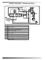
WIRING DIAGRAMS - SCHEMI ELETTRICI
IN Switch - Interruttore.
M Motor - Motore.
TR
Transformer - Trasformatore.
CF
Flame Control - Controllo amma.
IG Igniter - Accenditore.
FO
Photoresistance - Fotoresisteza.
FU
Fuse - Fusibile.
TA Room thermostat - Termostato ambiente.
AT Autotransformer - Autotrasformatore.
ST Dual-voltage switch - Interruttore cambiatensione.
L
Line - Linea.
N
Neutral - Neutro.

ACCESSORIES - ACCESSORI
MANOMETER
MANOMETRO
ROOM THERMOSTAT
TERMOSTATO AMBIENTE
WHEELS AND HANDLE KIT
KIT RUOTE E MANIGLIA

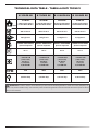
TECHNICAL DATA TABLE - TABELLA DATI TECNICI
B 35CED DV B 70CED DV B 100CED DV B 150CED DV
MAX
10 kW-кВт
8.600 kcal/h-ккал/ч
34.200 Btu/h-БТЕ/ч
20 kW-кВт
17.200 kcal/h-ккал/ч
68.300 Btu/h-БТЕ/ч
29 kW-кВт
25.000 kcal/h-ккал/ч
99.300 Btu/h-БТЕ/ч
44 kW-кВт
37.900 kcal/h-ккал/ч
150.500 Btu/h-БТЕ/ч
280 m³/h-м³/ч 400 m³/h-м³/ч 800 m³/h-м³/ч 900 m³/h-м³/ч
0,8 kg/h-кг/ч 1,6 kg/h-кг/ч 2,3 kg/h-кг/ч 3,5 kg/h-кг/ч
DIESEL-KEROSENE
дизель-керосин
DIESEL-KEROSENE
дизель-керосин
DIESEL-KEROSENE
дизель-керосин
DIESEL-KEROSENE
дизель-керосин
15 l-л 19 l-л 44 l-л 44 l-л
~110/240 V-В
(-15%÷10%)
50 Hz-Гц
0,70/0,35 A
0,08 kW-кВт
~110/240 V-В
(-15%÷10%)
50 Hz-Гц
1,6/0,8 A
0,18 kW-кВт
~110/240 V-В
(-15%÷10%)
50 Hz-Гц
2/1 A
0,23 kW-кВт
~110/240 V-В
(-15%÷10%)
50 Hz-Гц
2,4/1,2 A
0,28 kW-кВт
RPM
1425 2850 2850 2850
0,20 bar-бар 0,36 bar-бар 0,27 bar-бар 0,34 bar-бар
IMPORTANT: In order to have a correct function you must use an electrical generator in class G3 or more (frequency va-
riation ±1%, tension variation ±2%). The maximum power of electrical generator must be three time the nominal power of device
that you must connect.

►en - DISPOSAL OF THE PRODUCT
-This product has been designed and manufactured with top-quality materials and components, which can be
re-cycled and re-used.
-When a crossed-wheely bin symbol is attached to the product, it means that the product is protected by the,
2012/19/UE European Directive.
-Please obtain information regarding the local dierentiated collection system for electrical and electronic
products.
-Respect local Standards in force and do not dispose of old products as normal domestic waste. Correct
disposal of the product helps to prevent possible negative consequences for health, the environment and
mankind.
►it - SMALTIMENTO DEL PRODOTTO
-Questo prodotto è stato progettato e fabbricato con materiali e componenti di alta qualità, che possono es
-
sere riciclati e riutilizzati.
-Quando ad un prodotto è attaccato il simbolo del bidone con le ruote segnato da una croce, signica che il
prodotto è tutelato dalla Direttiva Europea 2012/19/UE.
-Si prega di informarsi in merito al sistema locale di raccolta dierenziata per i prodotti elettrici ed elettronici.
-Rispettare le norme locali in vigore e non smaltire i prodotti vecchi nei normali riuti domestici. Il corretto smal-
timento del prodotto aiuta ad evitare possibili conseguenze negative per la salute dell’ambiente e dell’uomo.
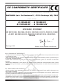
CE CONFORMITY CERTIFICATE
CE CONFORMITY CERTIFICATE - DICHIARAZIONE DI CONFORMITÀ CE
DANTHERM S.p.A. Via Gardesana 11, -37010- Pastrengo (VR), ITALY
Product: - Prodotto:
B 35CED DV - B 70CED DV
B 100CED DV - B 150CED DV
We declare that it is compliant with: - Si dichiara che è conforme a:
2014/30/EU, 2014/35/EU
EN 62233:2008, EN 61000-3-2:2014, EN 61000-3-3:2013, EN 55014-1:2006/
A2:2011, EN 55014-2:2015, EN 60335-1:2012/A11:2014, EN 60335-2-
102:2016
Pastrengo, 2019
Stefano Verani (Member of the Board)

4100.118 Edition 19 - Rev. 12
Dantherm S.p.A.
Via Gardesana 11, -37010-
Pastrengo (VR), Italy
Dantherm S.p.A.
Виа Гардесана 11, 37010
Пастренго (Верона), Италия
Dantherm Sp. z o.o.
ul. Magazynowa 5A,
62-023 Gądki, Poland
Dantherm Sp. z o.o.
ул. Магазинова, 5A,
62-023 Гадки, Польша
Dantherm LLC
ul. Transportnaya - 22 ownership 2,
142802, STUPINO, Moscow region, Russia
ООО «Дантерм»
Ул. Транспортная, владение 22/2,
142802, г.Ступино, Московская обл., РФ
Dantherm China LTD
Unit 2B, 512 Yunchuan Rd.,
Shanghai, 201906, China
Dantherm China LTD
Юньчуань роад, 512, строение 2В,
Шанхай, 201906, Китай
Dantherm SP S.A.
C/Calabozos, 6 Polígono Industrial, 28108
Alcobendas (Madrid) Spain
Dantherm SP S.A.
Ц/Калабозос, 6 Полигоно Индустриал,
28108 Алкобендас (Мадрит) Испания
-
 1
1
-
 2
2
-
 3
3
-
 4
4
-
 5
5
-
 6
6
-
 7
7
-
 8
8
-
 9
9
-
 10
10
-
 11
11
-
 12
12
-
 13
13
-
 14
14
-
 15
15
-
 16
16


Master B35-150CED DV 4100.118 E19R12 Manuale del proprietario
- Categoria
- Riscaldatori di spazio
- Tipo
- Manuale del proprietario
in altre lingue
Documenti correlati
-
Master B 35 70 100 150 CED DV GB Manuale del proprietario
-
-
-
Master XL 61 Manuale utente
-
-
-
-
-
-