
TRENCHER
XR SERIES
OWNERS MANUAL
MANUAL DE L’UTILISATEUR
BEDIENUNGSANLEITUNG
MANUALE
MANUAL DEL USUARIO
332/A1461
ISSUE 1
JUNE 07
PRINTED IN ENGLAND
OWNERS MANUAL
:
TRENCHER - XR SERIES
332/A1461
ISSUE 1
*332/A1461*
C053650
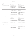
JCB Attachments, Riverside, Rugeley, Staffordshire WS15 2WA, England
Tel: 01889 572700

ENGLISH PAGES 1- 22
PAGES FRANÇAISES 1- 22F
DEUTSCHE SEITEN 1- 22G
PAGINAS EN ESPAÑOL 1- 22S
TESTO IN ITALIANO 1- 22L
A1461-1


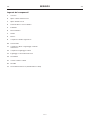
CONTENTS
INTRODUCTION
About this manual 1
Units of Measurement 1
Warranty 1
Carrier Machine - Suitability 1
GENERAL DESCRIPTION
Check List - Equipment 2
Attachment Identification 2
Component Identification 2
SAFETY
Safety First 3
Safety Check List 3
Decals 4
INSTALLING AND REMOVING
Safety First 6
Installing (JCB Robot 150, 160, 165, 170, 185,
190 1105, 1110, 1CX) 6
Removing (JCB Robot 150, 160, 165, 170, 185,
190 1105, 1110, 1CX) 7
Non JCB Carriers 7
OPERATION
Using the Attachment and Site Safety 8
Digging Chain Setup 10
Trench Widths and Depths 10
Digging with the Trencher 11
Travelling with the Trencher 12
On Site 12
On a Truck 12
Hydraulic Oils, Filtering and Cooling 13
MAINTENANCE
Safety First 15
Lubricants 15
Main Inspection 15
Check 15
Obtaining Replacement Parts 15
Washing 15
Service Schedules 16
Storage 17
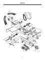
SERVICE
Fault Finding 18
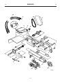
Main Components 19
Components Key 20
Torque Settings 21
SPECIFICATION 22
WARRANTY At rear of Manual
A1461-1


INTRODUCTION
1 1
About this Manual
This document details the relevant use and maintenance
procedures for the JCB Trencher. The safety information
included is directly relevant to operation and maintenance
of the Trencher. General safety information, and that
relevant to the carrier machine is not included. For details
about safe operation of the carrier machine, see the
relevant documents.
DO NOT ATTEMPT TO INSTALL, OPERATE OR
MAINTAIN ANY ATTACHMENT UNTIL YOU HAVE READ
AND UNDERSTOOD ALL RELEVANT OPERATOR
DOCUMENTATION FOR BOTH THE ATTACHMENT, AND
THE CARRIER MACHINE. PAY PARTICULAR
ATTENTION TO SAFETY INFORMATION. YOU MUST
OBSERVE ALL RELEVANT LAWS AND REGULATIONS.
The manufacturer’s policy is one of continuous
improvement. The right to change the specification of the
machine without notice is reserved. No responsibility will
be accepted for discrepancies which may occur between
specifications of the machine and the descriptions
contained in this publication.
Units of Measurement
In this manual, the S.I. system of units is used. For
example, liquid capacities are given in litres. The Imperial
units follow in parenthesis ( ), for example 28 litres
(6 UK gal/7.2 US gal)
Warranty
A copy of the manufacturer's warranty is provided at the
rear of this manual. We advise you to read and understand
the warranty before using the machine.
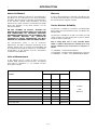
Carrier Machine Suitability
The Trencher is suitable for use with the JCB Robot Skid
Steer Loaders and 1CX Backhoe Loaders according to the
following table
The Trencher is suitable for use with some other non JCB
carrier machines. See the specification section for details
of typical carrier requirements.
Note: If fitting XR35 onto an early JCB Mk1 Robot
185HF - 1110HF 1” Quick Release couplings were used
and the additional parts listed below are required, as
follows:
1 x 1406/0026 - 1in BSP Bonded Washer
1 x 45/910100 - 1 in BSP Female Quick Release Connector
1 x 1606/0012 - 1 in BSP - 3/4 in BSPMale-Male Adaptor
A1461-1
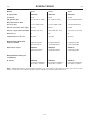
JCB Trencher
Carrier XR-35 XR-21 XR-14
Robot 185 HF, 190HF, 1105HF, 1110HF 980/A1452
Robot 185, 190, 1105, 1110 980/A1451
Robot 170HF, 165HF, 160HF 980/A1451
Robot 170 980/A1450
Robot 165 980/A1450
Robot 160 980/A1450
Robot 150 980/A1450
1CX HF (208 HF USA) 980/A1451
1CX (208 USA) 980/A1450
Includes
USA
Machines

GENERAL DESCRIPTION
2 2
Check List - Equipment
The Trencher is supplied as a complete unit with hoses and
options as required.
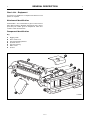
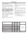
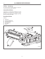
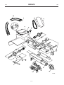
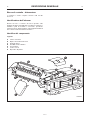
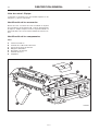
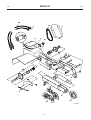
Attachment Identification
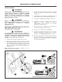
Serial Number - The serial number is given on the Trencher
rating plate X. When obtaining replacement parts always
quote the part number given on dataplate Y which also
contains technical information.
Component Identification
Key
A Digging Chain
B Drive Chain Cover
C Trencher Mounting Bracket
D Hydraulic Hoses
E Trencher Housing
F Motor Cover
G Cleaner
A1461-1
C053640
C
G
B
X
F
E
D
Y
A

SAFETY
3 3
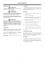
Safety First
All mechanical equipment can be hazardous if operated
without care or correct maintenance.
In this manual you will find warning messages. Read them.
Understand them. They tell you of hazards and how to
avoid them. If you do not understand the messages, ask
your employer or local JCB Distributor.
But safety is not just a matter of responding to the warn-
ings. All the time you are working with the attachment you
must be thinking what hazards there might be and how to
avoid them.
Do not work with the attachment until you are sure that you
can control it.
Do not start any job until you are sure that you and those
around you will be safe.
If you are unsure of anything, about the machine or the job,
ask someone who knows. Don’t assume anything - check
it out.
Remember
BE CAREFUL
BE ALERT
BE SAFE
Now read the rest of this section before moving on to the
rest of the manual.
B-1-1-2/1
Safety Check List
!!
DANGER
Lightning
Lightning can kill you. Do not use the equipment if there is
lightning in your area.
A-1-3-5
!!
WARNING
Decals
You can be injured if you do not obey the decal safety
instructions. Keep decals clean. Replace unreadable or
missing decals with new ones before operating the
machine. Make sure replacement parts include warning
decals where necessary.
INT-1-3-4
!!
WARNING
Equipment Condition
Defective equipment can injure you or others. Do not
operate equipment which is defective or has missing parts.
Make sure the maintenance procedures in this manual are
completed before using the equipment.
A-1-4-1
!!
WARNING
Manual
You and others can be injured if you fit, operate or maintain
the attachment without first studying this manual. If you do
not understand anything, ask your employer or JCB
Distributor to explain it. Keep this manual clean and in
good condition.
B-1-1-3/2
!!
WARNING
Regulations
Obey all laws, worksite and local regulations which affect
you and your equipment.
A-1-3-6
!!
WARNING
Care and Alertness
All the time you are working with the attachment, take care
and stay alert. Always be careful. Always be alert for
hazards.
B-1-1-4/1
!!
WARNING
Alcohol and Drugs
It is extremely dangerous to operate machinery when under
the influence of alcohol or drugs. Do not consume alcoholic
drinks or take drugs before or whilst operating the machine
or attachments. Be aware of medicines which can cause
drowsiness.
INT-1-3-9
A1461-1
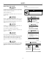
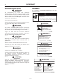
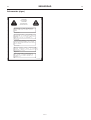
Each safety notice starts with a signal word. The
meanings of the signal words are given below.
!!
DANGER
Denotes an extreme hazard exists. If proper
precautions are not taken, it is highly probable that
the operator (or others) could be killed or
seriously injured.
INT-1-2-1
!!
WARNING
Denotes a hazard exists. If proper precautions are
not taken, the operator (or others) could be killed
or seriously injured.
INT-1-2-2
!!
CAUTION
Denotes a reminder of safety practices. Failure to
follow these safety practices could result in injury
to the operator (or others) and possible damage to
the machine.
INT-1-2-3

SAFETY
4 4
Safety Check List (cont’d)
!!
WARNING
Practice
You and others can be killed or injured if you do unfamiliar
operations without practising them first. Practice away
from the work site on a clear area.
Keep other people away.
Do not perform new operations until you are sure you can
do them safely.
INT-2-1-1
!!
WARNING
Equipment Condition
Defective equipment can injure you or others. Do not
operate equipment which is defective or has missing parts.
Make sure the maintenance procedures in this manual are
completed before using the equipment.
A-1-4-1
!!
CAUTION
Equipment Limits
Operating the equipment beyond its design limits can
cause damage. It can also be dangerous.
Do not operate the equipment outside its limits.
Do not try to upgrade the equipment’s performance by
unapproved modifications.
A-1-4-2
!!
CAUTION
Communications
Bad communication can cause accidents.
Keep people around you informed of what you will be
doing. If you will be working with other people make sure
you all understand any hand signals you will be using.
Work sites can be noisy. Do not rely on spoken commands.
A-1-4-3
!!
CAUTION
Metal Splinters
You can be injured by flying metal splinters when driving
metal pins in and out. Use a soft faced hammer or drift to
remove and fit metal pins. Always wear safety glasses.
INT-3-1-3
Decals
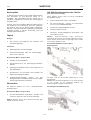
The following decals are fitted to the Trencher:
A1461-1
CONTACT WITH MOVING CHAIN OR AUGER may
cause death or serious injury.
Operate only from loader seat. Stay 10FT (3 m) or more
away from machine and trench when in operation
!!
DANGER
!!
CAUTION
TO AVOID INJURY
DO NOT USE THIS SUR-
FACE AS A STEP
USE ONLY INDICATED
AREAS FOR STEPPING
INTO LOADER
!!
CAUTION
MISSING SAFETY COVERS
may cause injury from moving
parts. Install and secure all covers
before operation
!!
WARNING
AVOID INJURY OR DEATH
BEFORE LEAVING LOADER
1 STOP TRENCHER
2 ROLL BACK LOADER TILT ARMS AND
PUT COMPLETE LENGTH OF TRENCHER
ON THE GROUND
3 TURN OFF LOADER
FAILURE TO HEED CAN RESULT
IN DEATH OR SERIOUS INJURY
!!
WARNING
AVOID INJURY OR DEATH
READ AND UNDERSTAND
OPERATORS MANUAL
BEFORE OPERATING OR
SERVICING MACHINE
CHECK FOR UNDERGROUND
UTILITY LINES
STAY 20FT (6 M) OR MORE AWAY
UNLESS OPERATING MACHINE
817/20004
817/20002
817/20007
817/20003
817/20005

SAFETY
5 5
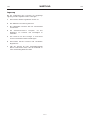
Decals (cont’d)
A1461-1

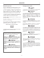
INSTALLING AND REMOVING
6 6
Safety First
!!
CAUTION
Hydraulic Pressure
Hydraulic fluid at system pressure can injure you.
Before disconnecting or connecting hydraulic hoses,
stop the engine and operate the controls to release
pressure trapped in the hoses. Make sure the engine
cannot be started while the hoses are open.
INT-3-1-11/1
!!
CAUTION
Take care when lifting/handling. Refer to
SPECIFICATION for the attachment weight.
B-2-1-2/2
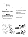
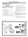
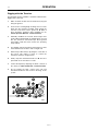
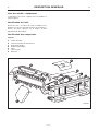
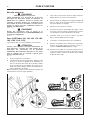
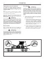
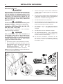
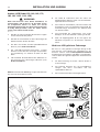
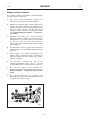
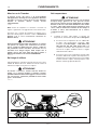
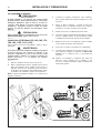
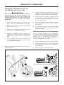
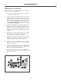
Installing (JCB Robot 150, 160, 165, 170,
185, 190, 1105, 1110, 1CX)
To engage an attachment on the Quickhitch, do the
following:
!!
WARNING
If two people are doing this job, make sure that the
person working the controls is a competent operator. If
the wrong control lever is moved, or if the controls are
moved violently, the other person could be killed or
injured.
2-2-6-5
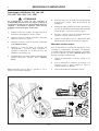
1 Align the machine square to the attachment.
2 Lower the loader arm fully to bring the hitch plate A
below the level of the lips on the attachment. Make
sure the hitch locking mechanism is unlocked as
detailed in the machine operators manual.
Note: The illustration below is typical and does not refer to
a specific machine.
3 Drive the machine slowly forward. Stop when the hitch
plate A just touches the attachment.
4 Raise the loader arm and engage the hitch plate A in
the lips on the attachment. Stop the movement as
soon as the plate is engaged.
5 Fully roll back the attachment.
6 Disable the hydraulic function of the machine, turn off
the engine and apply the park brake as detailed in the
machine operators manual.
7 Lock the attachment onto the hitch as detailed in the
machine operators manual.
8 The attachment is now locked onto the Quickhitch.
9 Connect the attachment tail hoses to the appropriate
auxiliary circuit pipework, (check machine Operator
Manual for correct procedure).
10 Return to the machine make sure all persons are clear
of the machine and attachment, start up the machine
as detailed in the operators manual.
A1461-1
0876
A
X
Y
Y

INSTALLING AND REMOVING
7 7
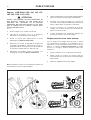
Removing (JCB Robot 150, 160, 165, 170,
185, 190, 1105, 1110 and 1CX)
!!
WARNING
If two people are doing this job, make sure that the
person working the controls is a competent operator. If
the wrong control lever is moved, or if the controls are
moved violently, the other person could be killed or
injured.
2-2-6-5
1 Use the drive control lever to stop and park the
machine on level ground.
2 Use the loader arm control lever to lower the
attachment to the ground.
3 Stop the engine and relieve hydraulic circuit pressure
(see Operator Manual).
4 Push forward the hydraulic safety control restraint bar.
Dismount from the machine or get someone else to
perform steps 5 and 6.
5 If appropriate, disconnect the attachment tail hoses
from the loader arm pipework (see Operator Manual).
Note: The illustration below is typical and does not refer to
a specific machine.
6 Pull levers X fully out beyond the sides of the hitch
plate A to retract the Quickhitch locking pins Y.
7 Return to the cab seat (or make sure your assistant is
well clear of the Quickhitch). Pull back the Safety
Restraint Bar. The attachment is now ready for use.
8 Operate the loader arm control lever to the right as if
to roll forward the attachment.
9 When the hitch plate A has disengaged from the lips
on the attachment, reverse the machine clear.
Non-JCB Carriers
For Non-JCB carriers reference should be made to the
trenchers mechanical and hydraulic specifications. Refer to
the carriers Owners Manual for instructions on installing
and removing attachments. However the following general
points should be observed.
1 Position the trencher on firm, flat ground.
2 Make the carrier safe, e.g. parking brake engaged,
engine stopped, hydraulic pressure released.
3 Use adequate lifting equipment.
A1461-1
0876
A
X
Y
Y

OPERATION
8 8
Using the Attachment and Site Safety
This section explains some techniques for efficient and
safe use of the machine and its attachment. Attention is
also drawn to the various safety aspects of operating on
site. Read and understand this section before you start
working with the machine. Practise using the attachments
until you are completely familiar with the controls and what
they do.
Before you start using the machine, tell your work mates
what you you will be doing and where you will be working.
On a busy site, use a signalman.
Remember that your machine is mobile. Whenever
possible, manoeuvre your machine into a position which
combines safety with efficiency.. If you have to choose,
remember that:
SAFETY MUST COME FIRST
!!
WARNING
Work sites can be hazardous. Inspect the site before
working on it. Look for potholes, weak ground, hidden
rocks etc. Check for utilities such as electric cables
(overhead and underground), gas and water pipes etc.
Mark the position of the underground cables and pipes.
Make sure that you have enough clearance beneath
overhead cables and structures.
INT-2-2-1
!!
WARNING
Before you start using the machine, inspect the job site.
You could be killed or injured if the ground gives way
under your machine or if piled material collapses onto
it. Check for potholes and hidden debris, logs, ironwork
etc. Any of these could cause you to lose control of
your machine.
2-2-5-2
!!
WARNING
You and/or your company could be legally liable for any
damage you may cause to public utilities. It is your
responsibility to make sure that you know the locations
of all public utility cables or pipes on the site which
could be damaged by your machine.
2-2-5-3
!!
WARNING
You could be electrocuted or badly burned if you get
the machine or its attachments too close too electrical
power cables
You are strongly advised to make sure that the safety
arrangements on site comply with the local laws and
regulations concerning work near electric power lines.
Buried Electric Power Cables
Before you start using the machine, check with your
electricity supplier if there are any buried power cables
on the site.
Overhead Electric Power Cables
There is a minimum clearance required for working
beneath overhead power cables. You must obtain
details from you local electricity supplier.
2-2-5-4
!!
WARNING
Reworking Old Sites
There could be dangerous material such as asbestos,
poisonous chemicals or other harmful substances
buried on the site. If you uncover any containers or you
see any signs of toxic waste, stop the machine and
advise the site manager immediately.
2-2-5-5
!!
WARNING
Water Supplies and Drains
Before you start using the machine, check with your
local public water supplier if there are buried pipes and
drains on the site. If there are, obtain a map of their
locations and follow the advice given by the water
supplier
You are strongly advised to make sure that the safety
arrangements on site comply with the local laws and
regulations concerning work near buried water pipes
and drains.
2-2-5-6
!!
WARNING
Communication
Bad communications can cause accidents. Keep
people around you informed of what you will be doing.
If you will be working with other people, make sure any
hand signals that may be used are understood by
everybody. Work sites can be noisy, do not rely on spo-
ken communication.
INT-2-2-3
A1461-1

OPERATION
9 9
!!
WARNING
Underground Gas Pipes
Before you start using the machine, check your local
gas supplier if there are any buried gas pipes on the
site.
If there are buried gas pipes we recommend that you
ask the gas company for any specific advice regarding
the way you should work on the site.
Some modern gas pipes cannot be detected by metal
detectors, so it is essential that an accurate map of
buried gas pipes is obtained before any excavation
work commences.
Hand dig trial holes to obtain precise pipe locations.
Any cast iron pipes found should be assumed to be gas
pipes until contrary evidence is obtained.
Older gas pipes can be damaged by heavy vehicles
driving over the ground above them.
LEAKING GAS IS HIGHLY EXPLOSIVE
If a gas leak is suspected, contact the local gas
company immediately and warn all personnel on the
site. Ban smoking, ensure that all naked lights are
extinguished and switch off any engines that may be
running.
You are strongly advised to make sure that the safety
arrangements on site comply with the local laws and
regulations concerning work near buried gas pipes.
2-2-6-1/1
!!
WARNING
Hillsides
Operating the machine on hillsides can be dangerous if
proper precautions are not taken. Ground conditions
can be changed by rain, snow, ice etc. Check the site
carefully.
Going uphill, reverse when unloaded and travel forward
when loaded. Going downhill, travel forwards when
unloaded and reverse when loaded.
Take special care when moving across a slope. If the
slope is too steep your machine could roll over. If you
must drive across a slope, keep the attachments close
to the ground.
3-1-1-4/1
!!
WARNING
Banks and Trenches
Banked material and trenches can collapse. Do not
work or drive too close to banks and trenches where
there is danger of collapse.
INT-2-2-5
!!
WARNING
Safety Barriers
Underguarded machines in public places can be
dangerous. In public places, or where your visibility is
reduced, place barriers around the work area to keep
people away.
INT-2-2-8
A1461-1

OPERATION
10 10
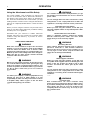
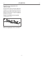
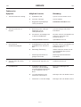
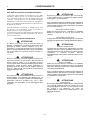
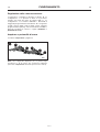
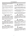
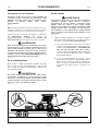
Digging Chain Setup
It is recommended that the digging chain is set up as
shown in illustration A. That is in a ‘V’ configuration with the
single tooth 1 in the centre and leading point of the ‘V’. The
‘V’ is formed by using progressively wider spacers 2 and
teeth 1, so that as the chain 3 rotates the cut becomes
wider. Refer to Trench Widths and Depths for width and
depth limits.
Trench Widths and Depths
Refer to Specifications on page 22.
Note: Optional Trencher Chain Kits and Trencher Cleaners
are available (see Specification at the end of this section).
A1461-1
0881
A
2
2
1
1
3

OPERATION
11 11
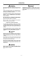
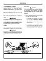
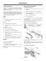
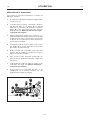
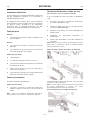
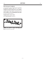
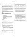
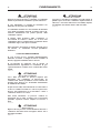
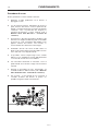
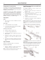
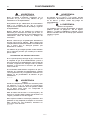
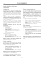
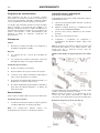
Digging with the Trencher
The following specific guidelines should be followed when
digging with a trencher.
1 Make an initial cut with the trencher boom 1 lying flat
along the ground.
2 As the chain is rotating begin inserting the nose of the
boom into the ground as A while slowly raising the
trencher a few inches off the ground as B. Both of
these operations should be done gradually (see the
Carrier Operator Manual - Loader Controls).
3 Gradually establish the trencher boom angle. Best
results will be obtained with an angle between 45
o
and
60
o
. The skid shoe 2 should be just above ground
level. Make certain the trench cleaner 3 is operating
freely if fitted.
4 The digging chain should rotate anticlockwise as at C
when viewed from the drive chain casing 4 side.
5 Whenever possible always dig along the centre line of
the trench. This makes it easier to control the
machinery and dig a straight trench.
6 Gently creep the carrier backwards as at D. Too fast a
speed will cause the trencher to stall.
7 Control the depth by adjusting the boom controls of
the carrier (see Operator Manual - Loader Controls).
8 Do not engage the ‘float’ control of the arm and
attachment if fitted as this increases the drag on the
system.
A1461-1
0880
4
A
C
D
B
1
2
3

OPERATION
12 12
Travelling with the Trencher
The safe transit of the load is the responsibility of the
transport contractor and driver. Any machine,
attachments or parts that may move during transit
must be adequately secured.
5-2-5-9
Note: Before transporting the machine make sure you will
be obeying the rules and laws of all the areas that the
machine will be carried through.
Make sure that the transporting vehicle is suitable. See
Static Dimensions (SPECIFICATIONS section of the
Carrier Owners Handbook) for the dimensions of your
machine.
!!
WARNING
Before moving the machine onto the trailer, make sure
that the trailer and ramp are free from oil, grease and
ice. Remove oil, grease and ice from the machine tyres.
Make sure the machine will not foul on the ramp angle.
See Static Dimensions in SPECIFICATIONS section for
the minimum ground clearance of your machine
2-2-7-5/1
On Site
Raise the carrier loader arm so that the attachment is
approximately 200 mm (8 in) above the ground. When
moving around the site follow as level a route as possible.
!!
WARNING
Never travel at excessive speed over rough terrain. The
resulting loss of control could cause the carrier to tip
over. This could lead to death or serious personal injury
as well as damage to the attachment and/or carrier.
B-1-2-11
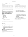
On a Truck
!!
WARNING
Water, mud, ice, grease and oil on ramps or trailers can
cause serious accidents. Make sure ramps and trailers
are clean before driving onto them. Use extreme
caution when driving onto ramps and trailers. Always
reverse up a ramp if unloaded, travel forwards if loaded.
Always reverse down a ramp if loaded, travel forwards
if unloaded.
3-1-1-3
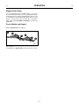
1 Drive the carrier up the ramps and onto the truck after
proceeding as described for On Site.
a If the attachment is being transported alone, lower
the assembly to the floor of the truck. Remove
from the machine (see Removing - JCB Robot
150, 160, 165, 170, 185, 190, 1105, 1110 and
1CX) and drive the carrier off the truck. Secure the
attachment to the truck using straps or chain of
sufficient strength.
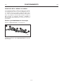
b If the attachment is being transported with the
machine, lower the assembly to the floor of the
truck and switch off the engine. Block the wheels
and using the attachment points chain the carrier
to the bed of the truck as shown in the illustration.
A1461-1
0879

OPERATION
13 13
Hydraulic Oils, Filtering and Cooling
Introduction
Generally speaking the hydraulic oil specified for the carri-
er can be used in the Trencher. However, since working
with the Trencher will heat the oil much more than excava-
tion work, the viscosity of the oil must be checked period-
ically when working in hot climates.
When the Trencher is used continuously, the temperature of
the hydraulic oil normalises at a certain level depending on
conditions and the carrier. At this temperature, the viscosi-
ty of the hydraulic oil should be 20 - 40 cSt (2.90 - 5.35
o
E).
The Trencher must not be started if the viscosity of the
hydraulic oil is above 1000 cSt (131
o
E) or operated when
the viscosity of the hydraulic oil is below 15 cSt (2.35
o
E).
Possible Result of using incorrect Oil
Oil too thick:
- Difficult start up.
- Stiff operation.
- Danger of cavitation in the pumps and motor.
- Sticky Valves.
- Filter bypass, impurities in oil not removed.
- Motor runs slowly.
Oil too thin:
- Efficiency losses (internal leaks).
- Damage to gaskets and seals, leaks.
- Accelerated wearing of parts, because of decreased
lubrication efficiency.
Note: We recommend different hydraulic oils for use in
summer and winter if there is an average temperature
difference of more than 35
o
C (95
o
F).
Special Oils
In some cases special oils (e.g. biological oils and non-
inflammable oils) can be used with the Trencher. Observe
the following aspects when considering the use of special
oils.
- The viscosity range in the special oil must be in the
given range (15 - 1000 cSt).
- The lubrication properties must be good enough.
- The corrosion resistance properties must be good
enough.
Note: Although a special oil could be suitable for the
carrier, it may not be suitable for the Trencher. Please check
with your JCB Distributor.
JCB OWNERS SHOULD ALWAYS CONSULT THEIR JCB
DISTRIBUTOR BEFORE CHANGING THE MACHINE
HYDRAULIC OIL.
Hydraulic Oil Purity
No separate filter is required for the Trencher. The carrier’s
oil filter will clean the oil flowing through the Trencher. The
purpose of the oil filter is to remove impurities from the
hydraulic oil since they cause accelerated component
wear, blockages and even seizure. Impurities also cause
the oil to heat and deteriorate. Air and water are also impu-
rities in oil. Not all impurities can be seen with the naked
eye.
Impurities enter the hydraulic system:
- During hydraulic oil changes and refilling.
- When components are repaired or serviced.
- When the Trencher is being installed on the carrier.
- Because of component wear.
Oil Filter
The carrier oil filter must fulfil the following specifications:
- The oil filter must allow maximum particle size of 25
microns (0.025 mm).
- The oil filter material must be man-made fibre cloth
or very fine gauge metallic mesh to withstand pres-
sure fluctuations.
- The oil filter must have a volume flow capacity of at
least twice the Trenchers maximum flow.
In general, oil companies guarantee new oils to have a
particle count of 40 microns maximum. When adding oil to
the system the oil must be filtered.
A1461-1

OPERATION
14 14
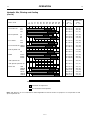
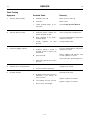
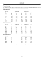
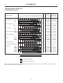
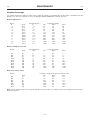
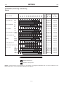
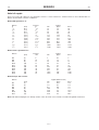
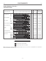
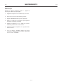
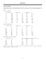
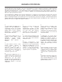
Hydraulic Oils, Filtering and Cooling
(cont’d)
A1461-1
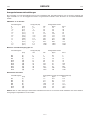
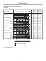
Viscosity Solidification
Name of Oil -4 14 32 50 68 86 104 122 140 158 176 °F 40 °C point
-20 -10 0 10 20 30 40 50 60 70 80 °C cSt (°E) °C (°F)
Shell Tellus Oil T32 32.0 (4.35) -50 (-58)
T37 37.0 (4.95) -40 (-40)
T46 46.0 (6.15) -35 (-31)
Neste Hydraulic 22 20.5 (2.95) -45 (-49)
46 44.0 (5.85) -39 (-38)
68 62.0 (8.20) -33 (-27)
Esso Univis N32 31.8 (4.32) -45 (-49)
N46 45.7 (6.20) -39 (-38)
Texaco Rando Oil HDZ32 32.0 (4.35) -45 (-49)
HDZ46 51.0 (6.75) -42 (-44)
Tebo Hydraulic Oil 32S 29.0 (3.95) -51 (-60)
46 46.0 (6.15) -51 (-60)
Mobil DTE13 29.4 (4.01) -45 (-49)
DTE15 44.9 (5.99) -46 (-51)
DTE16 65.9 (8.69) -42 (-44)
JCB Hydraulic Oil 32.0 (4.02) -50 (-58)
JCB Special Hydraulic Oil 46.0 (6.15) -35 (-31)
Motor Oils 10W 40.0 (5.35) -36 (-33)
20W/20 51.0 (8.05) -26 (-15)
SAE30 100 (13.2) -31 (-24)
5W/20 40.0 (5.35) -48 (-54)
10W/30 70.0 (9.25) -36 (-33)
15W/30 100 (13.2) -33 (-27)
1000 cSt 40 cSt 20 cSt 15 cSt
Permitted oil temperature
Recommended oil temperature
Note: JCB approves the use of Q8 Holbein 46 Biodegradable Oil with this breaker. Its properties are comparable to JCB
Special Hydraulic Oil.

MAINTENANCE
15 15
Safety First
!!
WARNING
Maintenance work must only be done by competent
personnel.
A-3-1-1
!!
WARNING
Equipment Condition
Defective equipment can injure you or others. Do not
operate equipment which is defective or has missing
parts.
Make sure the maintenance procedures in this manual
are completed before using the equipment.
A-1-4-1
!!
WARNING
Before doing any routine maintenance work on the
attachment while it is installed on the carrier, make the
carrier safe. Stop the engine and, if appropriate, ensure
that the parking brake is engaged and the drive is in
neutral. Remove the starter key to prevent the engine
being started.
B-3-1-2/3
Lubricants
In the EEC all JCB lubricants are covered by individual
COSHH (Control of Substances Hazardous to Health)
leaflets which are available on request from your JCB
Distributor.
It is most important that all personnel concerned with
lubricants read and understand the information contained
in the relevant leaflets.
Some general guidance is given in the JCB Carrier Machine
Handbook.
Main Inspection
We recommend that the following inspection is done dur-
ing the first 50 - 100 hours of operation of a new Trencher
attachment. It is advisable to have this work done by your
JCB Distributor.
Check
1 Torque tightness of all mounting and securing
bolts/nuts.
2 All hydraulic connections.
3 For hydraulic hoses rubbing (check throughout full
operating pressure).
4 Trencher operating pressure/flow (see SPECIFICA-
TION).
5 Hydraulic oil temperature during continuous operation
(see SPECIFICATION).
6 Correct operation of Spoil Auger.
7 Correct operation of Trench Cleaner Assembly.
8 Check digging teeth for cracks and wear.
9 Change the carrier hydraulic filter(s).
Obtaining Replacement Parts
We recommend that you fit only genuine JCB replacement
parts. Your distributor will need to know the equipments
serial number, which is stamped on the Trencher data
plate(see GENERAL DESCRIPTION section).
Washing
Periodically, and before doing any maintenance work, we
recommend that the outside of the Trencher is steam
washed. Ensure that the pressure and return lines are
plugged before washing, to prevent ingress of moisture.
A1461-1
La pagina si sta caricando...
La pagina si sta caricando...
La pagina si sta caricando...
La pagina si sta caricando...
La pagina si sta caricando...
La pagina si sta caricando...
La pagina si sta caricando...
La pagina si sta caricando...
La pagina si sta caricando...
La pagina si sta caricando...
La pagina si sta caricando...
La pagina si sta caricando...
La pagina si sta caricando...
La pagina si sta caricando...
La pagina si sta caricando...
La pagina si sta caricando...
La pagina si sta caricando...
La pagina si sta caricando...
La pagina si sta caricando...
La pagina si sta caricando...
La pagina si sta caricando...
La pagina si sta caricando...
La pagina si sta caricando...
La pagina si sta caricando...
La pagina si sta caricando...
La pagina si sta caricando...
La pagina si sta caricando...
La pagina si sta caricando...
La pagina si sta caricando...
La pagina si sta caricando...
La pagina si sta caricando...
La pagina si sta caricando...
La pagina si sta caricando...
La pagina si sta caricando...
La pagina si sta caricando...
La pagina si sta caricando...
La pagina si sta caricando...
La pagina si sta caricando...
La pagina si sta caricando...
La pagina si sta caricando...
La pagina si sta caricando...
La pagina si sta caricando...
La pagina si sta caricando...
La pagina si sta caricando...
La pagina si sta caricando...
La pagina si sta caricando...
La pagina si sta caricando...
La pagina si sta caricando...
La pagina si sta caricando...
La pagina si sta caricando...
La pagina si sta caricando...
La pagina si sta caricando...
La pagina si sta caricando...
La pagina si sta caricando...
La pagina si sta caricando...
La pagina si sta caricando...
La pagina si sta caricando...
La pagina si sta caricando...
La pagina si sta caricando...
La pagina si sta caricando...
La pagina si sta caricando...
La pagina si sta caricando...
La pagina si sta caricando...
La pagina si sta caricando...
La pagina si sta caricando...
La pagina si sta caricando...
La pagina si sta caricando...
La pagina si sta caricando...
La pagina si sta caricando...
La pagina si sta caricando...
La pagina si sta caricando...
La pagina si sta caricando...
La pagina si sta caricando...
La pagina si sta caricando...
La pagina si sta caricando...
La pagina si sta caricando...
La pagina si sta caricando...
La pagina si sta caricando...
La pagina si sta caricando...
La pagina si sta caricando...
La pagina si sta caricando...
La pagina si sta caricando...
La pagina si sta caricando...
La pagina si sta caricando...
La pagina si sta caricando...
La pagina si sta caricando...
La pagina si sta caricando...
La pagina si sta caricando...
La pagina si sta caricando...
La pagina si sta caricando...
La pagina si sta caricando...
La pagina si sta caricando...
La pagina si sta caricando...
La pagina si sta caricando...
La pagina si sta caricando...
La pagina si sta caricando...
La pagina si sta caricando...
La pagina si sta caricando...
La pagina si sta caricando...
La pagina si sta caricando...
La pagina si sta caricando...
La pagina si sta caricando...
La pagina si sta caricando...
La pagina si sta caricando...
La pagina si sta caricando...
La pagina si sta caricando...
La pagina si sta caricando...
La pagina si sta caricando...
La pagina si sta caricando...
La pagina si sta caricando...
La pagina si sta caricando...
La pagina si sta caricando...
-
 1
1
-
 2
2
-
 3
3
-
 4
4
-
 5
5
-
 6
6
-
 7
7
-
 8
8
-
 9
9
-
 10
10
-
 11
11
-
 12
12
-
 13
13
-
 14
14
-
 15
15
-
 16
16
-
 17
17
-
 18
18
-
 19
19
-
 20
20
-
 21
21
-
 22
22
-
 23
23
-
 24
24
-
 25
25
-
 26
26
-
 27
27
-
 28
28
-
 29
29
-
 30
30
-
 31
31
-
 32
32
-
 33
33
-
 34
34
-
 35
35
-
 36
36
-
 37
37
-
 38
38
-
 39
39
-
 40
40
-
 41
41
-
 42
42
-
 43
43
-
 44
44
-
 45
45
-
 46
46
-
 47
47
-
 48
48
-
 49
49
-
 50
50
-
 51
51
-
 52
52
-
 53
53
-
 54
54
-
 55
55
-
 56
56
-
 57
57
-
 58
58
-
 59
59
-
 60
60
-
 61
61
-
 62
62
-
 63
63
-
 64
64
-
 65
65
-
 66
66
-
 67
67
-
 68
68
-
 69
69
-
 70
70
-
 71
71
-
 72
72
-
 73
73
-
 74
74
-
 75
75
-
 76
76
-
 77
77
-
 78
78
-
 79
79
-
 80
80
-
 81
81
-
 82
82
-
 83
83
-
 84
84
-
 85
85
-
 86
86
-
 87
87
-
 88
88
-
 89
89
-
 90
90
-
 91
91
-
 92
92
-
 93
93
-
 94
94
-
 95
95
-
 96
96
-
 97
97
-
 98
98
-
 99
99
-
 100
100
-
 101
101
-
 102
102
-
 103
103
-
 104
104
-
 105
105
-
 106
106
-
 107
107
-
 108
108
-
 109
109
-
 110
110
-
 111
111
-
 112
112
-
 113
113
-
 114
114
-
 115
115
-
 116
116
-
 117
117
-
 118
118
-
 119
119
-
 120
120
-
 121
121
-
 122
122
-
 123
123
-
 124
124
-
 125
125
-
 126
126
-
 127
127
-
 128
128
-
 129
129
-
 130
130
-
 131
131
-
 132
132


JCB XR-35 Manuale del proprietario
- Tipo
- Manuale del proprietario
in altre lingue
- English: JCB XR-35 Owner's manual
- français: JCB XR-35 Le manuel du propriétaire
- español: JCB XR-35 El manual del propietario
- Deutsch: JCB XR-35 Bedienungsanleitung
Documenti correlati
Altri documenti
-
BCS Trencher Manuale del proprietario
-
H.Koenig MX18_ROUGE Manuale del proprietario
-
 Garbin TZ OPTIC FIBER 400 Use and Maintenance Manual
-
Husqvarna DS 40 GYRO Manuale del proprietario
-
Toro High-Speed Trencher Head, Compact Utility Loaders Manuale utente
-
 LSI LASTEM Greta Manuale utente
-
 Gravely Promaster 260Z Owner's And Operator's Manual
-
AG Neovo DR-22G Manuale utente
-
Toro High TorqueTrencher Head Manuale utente
-
Agria 5900 Manuale del proprietario


