
р в е я ю т с
JACK
SERVICE MANUAL

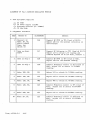
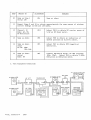
ALIGNMENT OF PLL & CARRIER OSCILLATOR PORTION
1. Test Equipment Required
a ) . RF VTVM
b ) . DC Power Supply (13.8V)
c ) . Frequency Counter (0 - 50MHz)
d ) . 50 ohm Load.
2. Alignment Procedure
STEP PRESET ТО
ÂDJUSTMENI
REMARKS
1
Channel: 40
Mode: AM, RX.
Clari: Center
Tone : Low
PA/СВ: CB
L16
Connect RF VTVM to TP4 ( lead of R112).
Adjust L16 for the maximum indication on
oscilloscope.
2
Same as above
EXE PT
L17
Connect DC Voltmeter to TP2 (lead of R117).
Adjust L17 to obtain 5.5V reading and
confirm beyound 2V in Low Band, channel 1.
3
Same as Step 1
L18
Connect RF VTVM to TP3 (lead of R81).
Adjust L18 for the maximum reading.
4
Same as Step 1
L20
Connect Frequency counter to TP3 (lead of
R81). Adjust L20 to obtain 16.7100MHz
reading.
5
Mode: USB, RX. L21
Adjust L21 to obtain 16.7125MHz reading.
6
Mode: LSB, RX.
L22 Adjust L22 to obtain 16.7075MHz reading.
7
Mode: LSB, TX.
VR6
Adjust VR6 to obtain 16.7075MHz reading.
8
Mode: LSB, RX.
L25 Connect Frequency counter to TP5 (lead of
R53). Adjust L25 to obtain 10.6975MHz
reading.
9
Mode: USB, RX.
L24
Adjust L24 to obtain 10.6925MHz reading.
10
Mode: AM, TX. L23
Connect Frequency counter to TP9(lead of
R84). Adjust L23 to obtain 10.6950MHz
read ing.
Form; AJT501-T-I JACK

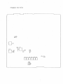
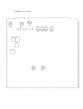
3. Test Equipment Connection
Form; AJT501—T—2 JACK

Alignment Test Point

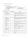
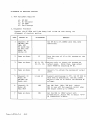
ALIGNMENT OF TRANSMITTER PORTION
1. Test Equipment Required
a ) . AF Signal Generator (1) for 500Hz and 1,000Hz
b ) . AF Signal Generator (2) for 2,400Hz
c ) . AF VTVM ( 150mV fu ll scale) d). RF VTVM (50V.full scale)
e). RF Powermeter (10W Max. Thruline type) f) . 50 ohm Dummy Load
g). Oscilloscope h). Harmonie Meter
i) . DC Voltmeter j). DG Ammeter (150mA fu ll scale)
2. Alignment Procedure
STEP
PRESET TO
ADJUSTMENT
REMARKS
1 Channel: 19
Mode: USB, TX.
No Modulation
VR10
Connect DC Ammeter to TP8(+), TP7(-).
Disconnect the PC-834AA. Adjust VR10 to
obtain the current approx.8mA.
2
Same as Step 1
VR9
Connect DC Ammeter to TP8(+), TP6(-).
Adjust VR9 to obtain the current approx.
100mA.
3 Channel : 19
Mode: USB, TX.
AF SG: 30mV,
Two Tone
500 and 2400Hz
L43 and L44
Disconnect the DC Ammeter. Connect PC-834.
Connect Powermeter, RF VTVM & Oscilloscope.
Set VR7 CW Max. Adjust the peak indica
tion of coils to 19CH.
4
Same as above
exept
Channel: 19
L42
Turn the coar of L41 to be fia t with upper
side of the c o il's cover. Adjust L42 for
the maximum indication.
5
Same as above
exept
Channel: 19
L41
Adjust L41 for the maximum indication.
While then, keep output voltage under 20V
by adjusting SG.
6
Same as above
Channel : 1
40
L41 Adjust L41 to obtain the minimum d iffé r
ence on the RF power meter between
Channel 40 and Channel 1.
7
Channel: 19
Mode: AM, TX.
90% modulation
L30 Adjust L30 to obtain the maximum indica
tion on the RF VTVM.
8 same as step 3
VR7
Adjust VR7 to obtain RF output of 24.5V on
the RF VTVM.
9
Same as Step 1
VR4
Adjust VR4 to obtain the minimum carrier
leakage.
Form; AJT501-T-3 JACK

STEP
PRESET TO
ADJUSTMENT
REMARKS
10 Same as Step 1
except LSB
VR4
Same as above
11
Repeat Steps 9 and 10 to obtain approximately the same amount of minimum
carrier leakege on USB and LSB modes.
12
Channel : 19
Mode: AM, TX.
No Modulation
VR11
Adjust VR11 to obtain RF carrier power of
5.0W on RF Power meter.
13 Same as above
VR8
Adjust VR8 to obtain an indication of
marked position on b uilt-in meter.
14 Same as above
exept
AF SG: 30mV
lKHz Mod.
VR5
Adjust VR5 to obtain 90% (negative)
modulation.
15
Same as above
except
Mode: FM
VR3
Connect Deviation meter. AF SSG supplies
lKHz, 30mV. Adjust VR3 to obtain 4.5KHz
Deviation on Deviation meter.
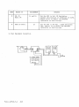
3. Test Equipment Connection
FM LINEAR DETECTOR
Form; AJT501-T-4 JACK

Alignment Test Point

ALIGNMENT OF RECEIVER PORTION
1. Test Equipment Required
a ) . RF SSG
b ) . DC Voltmeter
c ) . AF VTVM
d ) . Oscilloscope
2. Alignment Procedure
Connect the AF VTVM and 8 ohm dummy load to EXT SP Jack during the
alignment of receiver portion.
STEP
PRESET TO
ADJUSTMENT
REMARKS
1
Channel: 19
NB/ANL: OFF
SQL: OFF
RF GAIN: Max
AF VOL: Max
MODE: AM
CB/РА: CB
Set RF SG to 27.185MHz with 30%, 1kHz
modulation.
2
Same as above
L7
Turn the core of L7 to CW. maximum at the
bottom.
3
Same as above L6, 8, 10, 11
12, 13, 14.
Adjust coils to obtain the maximum AF
output power. While then, keep output
under 500mW by adjusting RF SG.
4
Same as abov e
L7
Adjust L7 to obtain the maximum AF output
power.
5
Channel: 18
Mode: AM
AB/ANL: ON
Band: mid.
LI and L2 Connect oscilloscope to TPl. Set RF SSG to
18ch with no modulation. (SG ATT.: 20dB)
Adjust LI and L2 to obtain the maximum DC
voltage.
6
Channel : 19
Mode: AM
SQL: MAX
VR2 Set SSG 19ch, lKHz, 30% Mod. Adjust
VR2 to turn o ff the squelch circu it when
SSG output comes up to lOOOuV.
7
Same as above VR1
Set the SSG to lOOuV output with
no-modulation. Adjust VR1 to obtain "S-9"
on transceiv er's meter.
Form; AJT501-T-5 JACK

STEP
PRESET TO ADJUSTMENT
REMARKS
8
CH: 19
Mode: FM
L3 and L4 Set the SSG to 5uV, N0 Modulation.
Connect Oscilloscope to TP10(lead of R279).
Adjust Coils to obtain the maximum
indication on Oscilloscope.
9 Same as above
L5
Set the SSG to FM lKHz, 1.5KHz Deviation
lmV. Adjust L5 to obtain the maximum
indication on Oscilloscope.
3. Test Equipment Connection
SIGNAL GENERATOR TRANSCEIVER
AF V T V M OSCILLOSCOPE
8 О
RESISTOR
Form; AJT501-T-6
JACK

AIignment Test Point

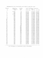
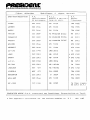
FREOUENCTES OF LOFAI. OSCTLLATORS ANI) TF STAFF IN RECKI.V1NC STATE
Channe1
Recept ion
Divide
Local O scillator Freq
uencics
No.
Freq uenc i es
(MHz)
Ratio
(N) AM/FM mode
(MHz)
USB mode'
LSB mode
1
26.965 79
16.270
16.272,5
16.2675
2
.975
80
16.280
16.2825
16.2775
3
.985
81 16.290
16.2925
16.2875
4
27.005
83 16.310
16.3125 16,3075
5
.015 84
16.320
16.3225 16.3175
6
.025 85
16.330
16.3325
16.3275
7 .035
86 16.340
16.3425 16.3375
8 .055
88
16.360
16.3625 16.3575
9 .065
89 16.370
16.3725 16.3675
10
.075
90
16.380
16.3825 16.3775
11
.085
91 16.390
16.3925
16.3875
12
.105
93 ■ 16.410
16.4125
16.4075
13
.115
94
16.420
16.4225
16.4175
14
.125
95 16.430
16.4325
16.4275
15 .135
96 16.440
16.4425
16.4375
16
.155
98 16.460
16.4625
16.4575
17
.165
99
16.470
16.4725 16.4675
18 .175
100
16.480
16.4825
16.4775
19
.185
101
16.490
16.4925 16.4875
20
.205
103
16.510
16.5125
16.5075
21 .215
104 16.520
16.5225
16.5175
22
.225
105
16.530
16.5325 16.5275
23 .255
108
16.560.
16.5625
16.5575
24
.235
106
16.540
16.5425
16.5375
25
.245
107
16.550
16.5525
16.5475
26 .265
109
16.570
16.5725
16.5675
27 .275
110 16.580 16.5825 16.5775
28
.285
111
16.590
16.5925
16.5875
29
.295
112
16.600
16.6025
16.5975
30
. 305
113
16.610
16.6125
16.6075
31
. 315
114
16.620
16.6225
16.6175
32
.32 5
115
16.630
16.6325
16.6275
33
.335
116 16.640
16.6425
16.6375
34
.34 5
117
16.650
16.6525
16.6475
35
. 355
118
16.660
16.6625
16.6575
36
.365
119
16.670
16.6725
16.6675
37
. 375
120
16.680
16.6825
16.6775
38
. 385
121
16.690
16.6925
16.6875
39
. 395
122 16.700
16.7025
16.6975
40
.405
123
16.710
16.7125
16.7075
ls t
IF Frequency is 10.
.69 S MHz on a il of 40 channels.

10.695MHz
10 695MHz
10. 695MHz
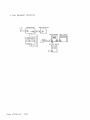
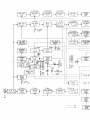
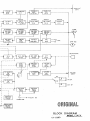
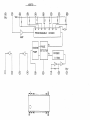
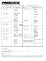
ANT
R X
TX
___
I
____
AM MOD
AMP
TR 46


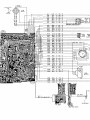
BLOCK DIAGRAM
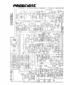
MODEL:JACK
U T - 5 3 9 D

рйш£юшах

ltKV5f*r > (IM( ff Sł

JACK
OM.CSS OTHCftWISC NOT£0.( r < 4HC «O -U iC H Or«ftAD t - 1+ r , А *Г А O л _
* . A LL CAAACTOAS Т ем *< *А П 1« е CHA*»CATCNlST«<* а Ч Ш Ш Д Ь . p l O ^ O O / . Q
• А АС * L t LC 1S ТИАМ «aOOFfr I ОЧ f f Ш ОАС ТМЛМ U • * • * • “*♦ W
0€S<«N tV OAAWN |Y
5?.3.i3
AATAQ »T .
WMIPCN N 0.
UT-339D
МООЕС МО.
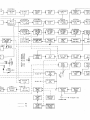
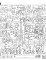
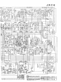
JACK

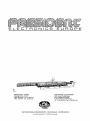
рвВБюет:
ELECTRONICS EUROPE
SX CAPITAL 20.000.000 F.F. • SIREN SETE3 IS S30 490
SIEGE SOCIAL
Route de SETE-BP 100
34540 BALARUC - Tél : 67.46.27.27
Télex : 490534F • Fax : 67.48.48.49
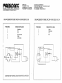
BRANCHEMENT PRISE MICRO 6 BROCHES NC 518
N* BROCHES
1
2
3
4
5
6
DESIGNATION CABLES
Modulation
RX
TX
Non connectée
Masse
Alimentation
ATTENTION BIEN VERIFIER LE BRANCHEMENT DE LA BROCHE 6
SUCCURSALE «ILE DE FRANCE»
50/56, Rue du Pré des Aulnes • Parc d'activités des Arpents
77340 PONTAULT- COMBAULT
Tél : (1) 60.29.28.27* Fax : (1) 60.28.44.00
BRANCHEMENT PRISE MICRO 4 BROCHES NC 514
N 4 BROCHES
1
2
3
4
DESIGNATION CABLES
Masse
Modulation
TX
RX

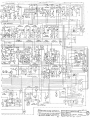
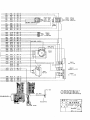
1C2 UPCI028HA
TRI l 2SC9-T5A
SCI730L Г-
. CAPACITANCE VALUES A flf iN d C A T fO Ж MICROfARAOS
UNLCSS OTMf.RWlSF. NOTEO. (P » MICRO - M ICR O* AR AP
. ALL CAPACTORS TEMPERATURE, CIIARC ATCR ISTICS
ARE SL (LF.SS TH A N lOOOPP ) РП TE (MORF. TMAN
lOOOPF » l»NtT SS OTHERWISE NOTTO ,
4»>P*
OESIf.N 8Y
fłP A* N P »
NOUVEAT
-HO Of l NO* r
JACK
-^ir»Ó c - '
тт л nia о -
с н е с * ь т
ИП 'ВО U'i
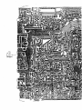
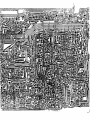
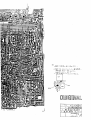
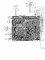
SCHEMATIC DIAGRAM
Jt-tJct*.
*n- '1/ ES? -01 HO
>OKA V VOLUMS

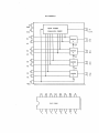
MB87I9
©
GNU
-----
<
О
I 9
La pagina si sta caricando...
La pagina si sta caricando...
La pagina si sta caricando...
La pagina si sta caricando...
La pagina si sta caricando...
La pagina si sta caricando...
La pagina si sta caricando...
La pagina si sta caricando...
La pagina si sta caricando...
La pagina si sta caricando...
La pagina si sta caricando...
La pagina si sta caricando...
La pagina si sta caricando...
-
 1
1
-
 2
2
-
 3
3
-
 4
4
-
 5
5
-
 6
6
-
 7
7
-
 8
8
-
 9
9
-
 10
10
-
 11
11
-
 12
12
-
 13
13
-
 14
14
-
 15
15
-
 16
16
-
 17
17
-
 18
18
-
 19
19
-
 20
20
-
 21
21
-
 22
22
-
 23
23
-
 24
24
-
 25
25
-
 26
26
-
 27
27
-
 28
28
-
 29
29
-
 30
30
-
 31
31
-
 32
32
-
 33
33


Altri documenti
-
Alpine TDA-7568R Manuale del proprietario
-
-
-
-
Realistic DX-300 Manuale utente
-
Schneider Electric TeSys™ T LTM R CANopen Guida Rapida
-
Sony TC-D6C Manuale utente
-
Technics SU-VX800 - service Manuale utente
-
Pioneer PR-8210-A Manuale utente
-
Hafler P4000 Manuale utente