Jøtul F 475 Installation And Operating Istructions
- Categoria
- Camini
- Tipo
- Installation And Operating Istructions

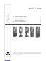
Jøtul F 470 Series
GB - Installation and Operating Instructions 2
FR - Manuel d’installation et d’utilisation 25
ES - Instrucciones para instalación 48
IT - Manuale di installazione ed uso 71
NL - Installatie- en montagehandleiding 94
Jøtul F 470 Series
Manual Versio P05
Jøtul F 471 Jøtul F 473 Jøtul F 474 Jøtul F 475 Jøtul F 476
The manuals which are enclosed with the product must be kept throughout the product’s entire service life. Les manuels fournis avec le produit doivent être
conservés pendant toute la durée de vie du produit. Los manuales suministrados con este producto deben guardarse durante todo el ciclo de vida del producto.
I manuali inclusi con il prodotto vanno conservati per l’intera durata di vita del prodotto. De bij de haard meegeleverde handleidingen moeten gedurende de
volledige gebruiksduur van de haard bewaard blijven.

2
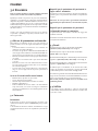
1.0 Technical data
Material: Cast iron
Finish: Black paint
Type of fuel: Wood
Max. log length: 30 cm
Smoke outlet: Top, rear
Flue pipe dimension: Ø 150 mm/min. 177 cm2
cross section
Outside air connection: Alu. flex - Ø 100 mm
Product weight:
Burn chamber: 143 kg
Base, cast iron 39 kg
Pedestal, cast iron 32 kg
Leg, cast iron 33 kg
Glass door in base 2,5 kg
Jøtul F 471, F 473, F474 and F 475
can be delivered with the following sides:
Cast iron sides 27 kg
Aluminium sides 3 kg
Glass sides 5.5 kg
Jøtul F 476:
Soapstone side panels 150 kg
Optional extra Floor plates, Outside air
connection, Rotating set for
the Jøtul F 473
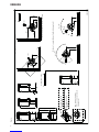
Product dimensions, distances: See Fig. 1
Technical data in acc. with EN 13240
Nominal heat output: 6,0 kW
Flue gas mass flow: 6,0 g/s
Recommended chimney draught: 12 Pa
Efficiency: 75,4%@6,3 kW
CO emissions (13% O2): 0,08%
Flue gas temperature: 305oC
Dust: < 20 mg/m3n @ 13% O2
Burn time: 2.0 kg/h
Operational type: Intermittent
Intermittent combustion here means normal use of a fireplace,
i.e. add more fuel as soon as the fire has burned down to embers.
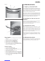
2.0 Relationship to the
authorities
• Installation of a fireplace must be carried out in compliance
with national laws and regulations. All local ordinances,
including those that refer to national and European standards,
must be complied with when products are installed.
• The installation can only be put into use after it has been
checked by a qualified inspector.
• Contact your local building authorities before installing a
new fireplace.
Table of contents
1.0 Technical data .............................................. 2
2.0 Relationship to the authorities ................... 2
3.0 Safety ............................................................ 3
4.0 Installation ..................................................8
5.0 Daily Use ......................................................18
6.0 Servicing ..................................................... 19
7.0 Maintenance .............................................. 23
8.0 Optional Extras ...........................................24
9.0 Warranty ....................................................24
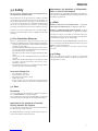
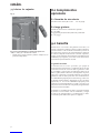
On all our products there is a label
indicating the serial number and
year. Write this number in the
place indicated in the installation
instructions.
Always quote this serial number
when contacting your retailer or Jøtul.
les combustibles recommandés.
Respectez les consignes d'utilisation. Utilisez uniquement
Verwenden Sie nur empfohlenen Brennstoffen.
Montage- und Bedienungsanleitung beachten.
Follow user`s instructions. Use only recommended fuels.
standard
Certificate/
The appliance can be used in a shared flue.
Minimum distance to adjacent combustible materials:
Emission of CO in combustion products
Serial no: Y-xxxx, Year: 200x
Manufacturer:
N-1602 Fredrikstad
Norway
Jøtul AS
POB 1441
Sweden
EUR Intermittent
Nominal heat output
Norway
Country
Operational type
Fuel type
Operation range
Efficiency
Klasse II
Classification
Standard
Flue gas temperature
Room heater fired by solid fuel
Product:
Jøtul
SP Sveriges Provnings- och
221546
Forskningsinstitut AB
SP Swedish National
Testing and Research
Institute
:
Approved by
:
:
:
:
:
:
:
Minimum distance to adjacent combustible materials:
OGC SP
EN
Serial no.
ENGLISH

3
3.0 Safety
NB! To guarantee optimal performance and safety, Jøtul stoves
must be fitted by a qualified installer.
Any modifications to the product by the distributor, installer
or consumer may result in the product and safety features not
functioning as intended. The same applies to the installation of
accessories or optional extras not supplied by Jøtul. This may
also be the case if parts that are essential to the functioning
and safety of the fireplace have been disassembled or removed.
In all these cases, the manufacturer is not responsible or liable
for the product and the right to make a complaint becomes null
and void.
3.1 Fire Prevention Measures
There is a certain element of danger every time you use your
fireplace. The following instructions must therefore be followed:
• The minimum safety distances when installing and using the
fireplace are given in fig. 1.
• Ensure that furniture and other flammable materials are not
too close to the fireplace. Flammable materials should not be
placed within 1 metre of the fireplace.
• Allow the fire to burn out. Never extinguish the flames with
water.
• The fireplace becomes hot when lit and may cause burns if
touched.
• Only remove ash when the fireplace is cold. Ash can contain
hot embers and should therefore be placed in a non-
flammable container.
• Ash should be placed outdoors or be emptied in a place where
it will not present a potential fire hazard.
In case of chimney fire:
• Close all hatches and vents.
• Keep the firebox door closed.
• Check the loft and cellar for smoke.
• Call the fire service.
• Before use after a fire an expert must check the fireplace
and the chimney in order to ensure that it is fully functional.
3.2 Floor
Foundation
You need to make sure the foundation is suitable for a fireplace.
See “1.0 Technical Data” for specified weight.
We recommend the removal of any flooring that is not attached
to the foundation (“floating floors”) beneath the installation.
Requirements for protection of wooden
flooring beneath the fireplace
The product has integrated floor protection and may therefore
be placed directly on a wooden floor.
Any inflammable floor coverings, such as linoleum, carpets, etc.
must be removed from under the product.
Requirements for protection of inflammable
floors in front of the fireplace
The front plate must comply with national laws and regulations.
Contact your local building authorities regarding restrictions and
installation requirements.
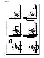
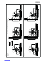
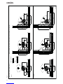
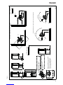
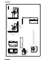
3.3 Walls
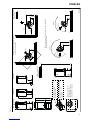
Distance to walls made of combustible material - see fig. 1a for
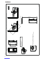
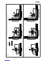
Jøtul F 471, F 473, F 474 and F 475. See fig. 1b for Jøtul F 476.
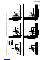
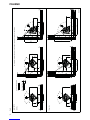
Distance to combustible wall protected by firewall: See fig. 1c
for Jøtul F 471, F 473, F 474 and F 475. See fig. 1d for Jøtul F 476.
The fireplace may be used with an uninsulated flue pipe
provided the distances between the fireplace and walls made
of combustible materials are as shown in fig. 1.
Ensure that furniture and other flammable materials are not too
close to the fireplace. Flammable materials should not be placed
within 1000 mm of the fireplace.
NB: Pay particular attention to this when using revolving
pedestal!
3.4 Ceiling
If the ceiling above the fireplace is made of a combustible
material, the minimum distance between the fireplace and
ceiling must be 1000 mm.
ENGLISH

4
ENGLISH
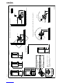
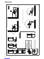
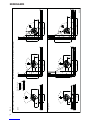
Fig. 1a
X
Y
Jøtul F 471/ F 475 Jøtul F 473 Jøtul F 474
900053-P03
max 90°
max 180°
155
155
1025
1180
740
460
Min 2180
490
230
230
160
1025
500
100
730
150
* Semi-insulated chimney / shielded flue pipe
440
360
590
500
730
385
200
200
200
385
385
545
775
*
*
*
410
640
Combustible ceiling
Hole in floor for external air supply
Ø100mm connection
Jøtul F 471, F 474
Hole in floor for external air supply
Ø100mm connection
Jøtul F 473
Min. measure floorplate
X/Y = Acc. to national standards
and regulations
Distance to combustible wall with rotating pedestal
Min. distance to combustible wall Combustible wall
1000
1000
1000 1000

5
ENGLISH
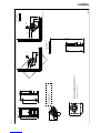
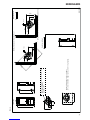
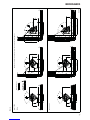
Fig. 1b
X
Y
Jøtul F 476
900053-P03
Min 2180
564
155
1025
1180
554
230
180
160
230
* Semi-insulated chimney / shielded flue pipe
500
782
604
374
50
200
200
440
440
622
852
**
*
100
424
654
Hole in floor for external air supply
Ø 100mm connection
Jøtul F471, F476
Min. measure floorplate
X/Y = Acc. to national standards
and regulations.
Combustible ceiling
Combustible wall
Min. distance to combustible wall
1000 1000


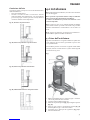
8
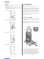
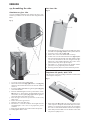
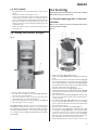
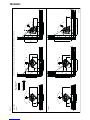
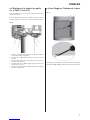
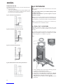
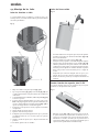
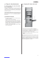
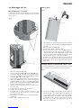
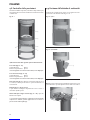
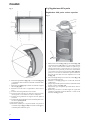
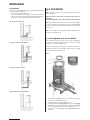
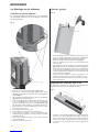
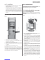
Air supply
The outside air connection may be fitted directly to the Jøtul F 470
through:
• The base/pedestal/leg or
• through a flexible supply hose from the outside/chimney
(only if the chimney has its own duct for external air) and to
the product's outside air connector.
Fig. 2A, through an outside wall
Fig. 2B, through the floor and ground plate
Fig. 2C, through the floor and basement
Fig. 2D, indirectly through an outside wall
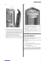
4.0 Installation
NB: Check that the fireplace is undamaged before installation
begins.
NB: The product is heavy! Ensure you have help when positioning
and installing it. Make sure the product does not topple over.
NB: The door must not be lifted using the handle before the
weights have been mounted. You will find the Installation and
Operating instructions and a bag of screws in the smoke outlet.
NB: Read the Installation and Operating instructions carefully
before installing the fireplace!
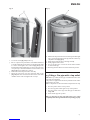
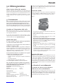
4.1 Prior to installation
The standard product comes in three or more consignments
One with the fireplace itself, one with the base, pedestal or leg
and side panels.
You will need the following tools to install the product: Spirit
level, ratchet with 10 mm and 13 mm sockets and hex keys with
4 mm and 5 mm sockets.
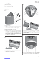
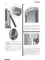
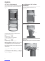
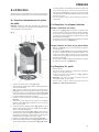
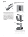
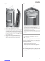
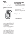
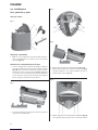
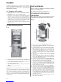
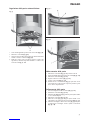
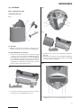
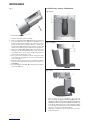
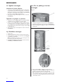
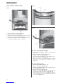
Fig. 3
1. Remove the packaging (cardboard and wooden frame) and
spread the cardboard out on the floor behind the fireplace.
2. Leave the stove standing on the transport pallet.
3. Remove the top plate (Fig. 3 A) with the top grate (Fig. 3 B).
4. Push the product’s right-hand and left-hand weights (Fig. 3 C)
out from the wooden pallet and put them to one side.
5. Check that the control handles (Fig. 3 D) move freely.
ENGLISH

9
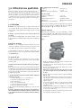
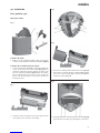
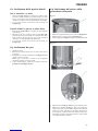
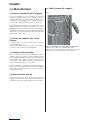
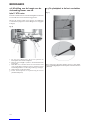
4.2 Installation
Base, pedestal and leg
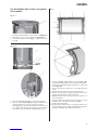
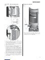
Only for base
Fig. 4
Through the floor
1. NB! If connecting the Flex Hose through a hole in the floor, do
not knock out the removable cover plates (Fig. 4 A).
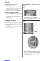
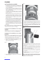
Through the rear outlet in the base
2. If attaching a Flex Hose (Ø 100 mm) for external air supply to
the external air connector (Fig. 4 B) beneath the burn chamber,
first drill a hole in the removable cover plates (Fig. 4 A) before they
are knocked out. Let the inner plate inside the base remain
in place when the cover plates are knocked out. Then remove
the shelf and inner plate in the base.
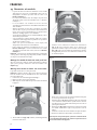
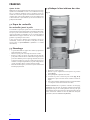
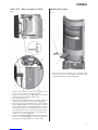
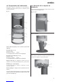
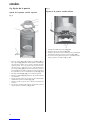
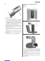
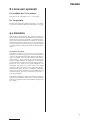
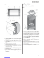
Fig. 5
3. Carefully lay the stove down on its back. Rest the stove on a
pallet and three packaging frames.
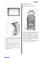
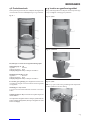
Fig.6
Fig. 7
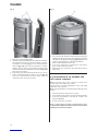
4. Remove the two screws for installation of the sides (Fig. 6 A).
5. Push the base up to the burn chamber (Fig. 7) and secure
it firmly with the four screws (M8 x 25 mm) and washers
provided. See Fig. 6 B.
Fig. 8
6. Loosen the height adjustment screws slightly (Fig. 8 A)
beneath the product so that they can be screwed by hand.
ENGLISH

10
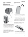
Fig. 9
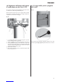
7. Carefully remove the wooden pallet.
8. Place a packaging frame (Fig. 9 A) crosswise underneath
the base/pedestal/leg and cardboard packaging in front of/
beneath the product to prevent it from making marks on the
floor. Carefully raise the stove and stand it in its proper place
(Fig 1). Remember to position it straight above or behind the
external air supply, whichever is applicable.
9. Place the top plate (Fig. 3 A) temporarily in place and level the
fireplace. If the stove is not standing level, adjust the screws
shown in Fig. 8 A until the product is perfectly straight.
10. If an external air supply is not going to be connected, refit any
parts that have been removed from the product.
11. If installing a Jøtul F 471, F 475 or F 476 base, the shelf must
be secured as described in Chapter 4.7.
12. If the control handles (Fig. 3D) are difficult to pull out, see
step 4.6
Installation with external air supply
Fig. 10 - Base
Fig. 10 - Pedestal
Fig. 10 - Leg
1. Attach the hose to the external air connector using a hose
clip (Fig. 10 A Base and leg) (NB! Do not fit a hose clip onto
the Jøtul F 473 pedestal with a rotating set as this prevents the
set from rotating). NB! Make sure the hose is long enough so
that joints are not necessary. The external air hose insulation
ends approx. 10 cm below the burn chamber.
2. Refit any parts that have been removed from the product.
ENGLISH

11
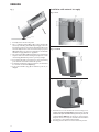
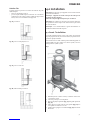
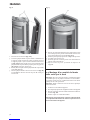
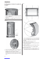
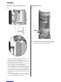
Jøtul F 475 – Base with glass door
Fig. 11
1. Assemble the cast iron base and external air supply as
described in the previous chapter.
2. Adjust the screws downwards (Fig. 8 A) by approx. 4 mm to
prevent the glass door from touching the floor.
3. Remove the shelf from the base.
4. Glue a resilient button from the bag of screws to the top and
bottom right-hand side of the base (fig. 11 G).
5. Attach the hinge for the glass door to the base using the
M6 x 20 mm screws (Fig. 11 A) which are in the bag of screws
for the glass door. Insert the springs (Fig. 11 B) between the
threaded holes and the hinge before tightening the screws.
There must be an even gap between the door and the base to
allow the door to hang straight. Adjust the door, if necessary,
by tightening or loosening the two screws (Fig. 11 A).
6. Fasten the screw (Fig. 11 C) M8 x 40 mm upside down using
the 2 nuts in the stiffener (Fig. 11 D) under the burn chamber.
Suspend the spring (Fig. 11 E) between screws C and F.
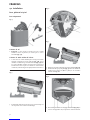
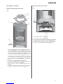
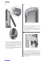
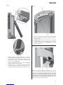
Mounting the weights
Fig. 12
1. Open the door handle completely (Fig. 12 A), raise the door
without touching the handle and push one of the wooden
packaging strips in (Fig. 12 B).
ENGLISH

12
Fig. 13
2. Loosen the screw at the top (Fig. 13 A) of the weight and thread
the wire in (Fig. 13 B). NB: Make sure that the screw passes
through the wire loop. Tighten the screw. It is also important
that the wire loop is facing the right way. The end of the wire
must be turned backwards.
3. Place the lower part of the weight in the section (Fig. 13 C) on
the side of the burn chamber.
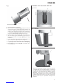
4. The door can now be raised and lowered using the handle.
NB: Remember that the handle must be completely open
before the door is raised or lowered.
Fig. 14
5. Remove the gloves and bowl from the ash pan. Place the
bowl on the top grate right up to the end if the flue pipe is
rear-mounted.
6. The weights (Fig. 14 A) that were in the bag of screws can be
mounted at the top rear of the door unless the door is self-
closing. The screws (Fig. 14 B) are in the bag of screws.
Fig. 15
7. NB! If the door handle is shut when the door is in the upper
position, it will be possible for the door to remain in this
position by dropping the door stopper (Fig. 15 A) into the slot
at the front (the product is not factory-finished with the door
stopper in this position.). The door must not be open when
the fire is lit. By loosening the screw (Fig. 15 B) and turning
the door stopper in under the handle, the door will be able
to close.
ENGLISH

13
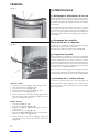
4.3 Chimney and flue pipe
• The fireplace must only be connected to a chimney and
flue pipe approved for solid fuel fireplaces with flue gas
temperatures as specified in «1.0 Technical Data».
• The cross-section of the chimney must be designed to fit the
fireplace. Use «1.0 Technical Data» to calculate the correct
chimney cross-section.
• The chimney must be connected in accordance with the
installation instructions of the chimney supplier.
• Before a hole is made in the chimney, the product should be
test-mounted in order to correctly mark the position of the
fireplace and the hole in the chimney. See Fig. 1 for minimum
dimensions.
• Make sure that the flue pipe rises all the way up to the
chimney.
• With a rear outlet, use a flue pipe bend with a sweep hatch
to allow sweeping.
• Please note that it is extremely important for connections to
have a degree of flexibility. This is to prevent any movement
in the installation leading to the formation of cracks.
• For recommended chimney draught, see «1.0 Technical Data».
For flue pipe dimensions with the relevant cross-section, see
“1.0 Technical Data”.
NB! The minimum recommended chimney length is 3.5 m from
the flue pipe insert. If the draught is too strong, a flue pipe
damper can be installed and used to reduce the draught.
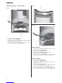
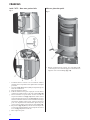
Fitting a flue pipe with a top outlet
With a top outlet, the flue pipe is installed after the outer sides
have been installed. See Chapter 4.4.
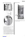
Fitting a flue pipe with a rear outlet
The product is supplied from the factory with the smoke outlet
fitted for the top outlet. NB: It is important to remove the white
foam plastic in the top. Proceed as follows for installation with
a rear outlet:
1. Place the product in the correct position. See Fig. 1.
2. Unscrew the smoke outlet from the top outlet.
3. Open the door and place it securely in the upper position by
closing the handle.
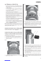
Fig. 16
4. Pull the baffles (Fig. 16 A) forward, lift slightly, turn and lower
them.
Fig. 17
5. Be sure to note how the exhaust deflectors (Fig. 17 A) are
positioned before removing them to ensure that they are
fitted back into exactly the right place. Take hold of the pin
(Fig. 17 B) on the underside of the exhaust deflectors, lift them
up slightly and then sideways before lowering and removing
them from the burn chamber.
Fig. 18
6. Unscrew the cover for the rear outlet on the inside of the burn
chamber and take it out through the door opening.
7. Attach the smoke outlet (Fig. 18 A) to the inside of the burn
chamber where the cover was. Note that it must be turned so
that the flue pipe can be pushed into place from the outside.
8. Place the gasket (Fig. 18 B) from the bag of screws around
the edge of the flue pipe and push it into the smoke outlet.
9. Install the smoke outlet cover where the outlet was.
10. Refit the exhaust deflector and baffle.
NB: It is important for the joints/flue pipes to be sealed
completely. Air leaks may prevent them from operating properly.
ENGLISH

14
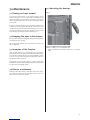
4.4 Assembling the sides
Aluminium or glass sides
If you are installing aluminium sides and the flue pipe is rear-
mounted, you will need to saw holes for this using a hacksaw
blade.
Fig. 19
1. Loosen the screws on the top (Fig. 19 A).
2. Attach the lower bracket (Fig. 19 B) with the screw (Fig. 6 A)
that was removed from the bottom of the burn chamber
earlier on.
3. If you are installing aluminium sides, glue the gaskets (Fig. 19 C)
onto all the brackets.
4. Move the aluminium/glass side into position in the section.
NB! If there is a crack between the aluminium panels and
the brackets, an extra gasket (Fig. 19 C) should be glued to
the bracket at the place where the crack is.
5. Move the upper section into position and secure loosely
with screws.
6. Do the same on the opposite side.
7. Adjust the sides at the back edge.
8. Check there is a clearance between the weights and the
aluminium/glass sides. If necessary, adjust the panels
outwards.
9. Refit any parts that have been removed from the product.
10. Finally, tighten all the screws.
Cast iron sides
Fig. 20
1. If installing the flue pipe at the back, first drill a hole in the
removable cover plates (Fig. 20 A) before they are knocked out.
2. Loosen the screws on the top (Fig. 19 A).
3. Put the sides on and secure with screws on the top.
4. Lock the sides onto the underside with screws (Fig. 6 A) that
were removed from the bottom of the burn chamber earlier
on. The sides should fit into the slots along the back edge.
Tighten the screws while holding the sides in the correct
position so that they do not slip out of place.
5. Check there is a clearance between the weights and the
panels. If necessary, adjust the panels outwards.
6. Refit any parts that have been removed from the product.
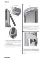
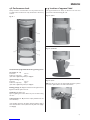
Soapstone side panels, Jøtul F 476
The side panels come in two packages. A bracket is mounted onto
each soapstone side panel.
Fig. 21
1. Move the bracket (Fig. 21 A) to the opposite position on one
of the soapstone side panels. This should only be done if the
bracket is not located in the upper position. Do not tighten
the screws so much that the bracket cannot be moved up and
down with your hand. Make sure the bracket on the other
side panel is equally as loose.
ENGLISH

15
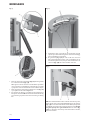
Fig. 22
2. Loosen the screws (Fig. 22 A) on the top.
3. Raise a soapstone side panel at the end in which the bracket
is mounted and place it into the base. Push the bracket until
it is at the same height as the screw hole (Fig. 22 A) on the
burn chamber. Then push the upper section of the soapstone
side panel up to the burn chamber and attach the screw
(Fig. 22 A). Do not tighten the screw yet.
4. Then fit the other side panel in the same way.
5. Attach the side panels onto the underside with screws
(Fig. 6A) that were removed from the bottom of the burn
chamber earlier on. Do not tighten the screw yet.
Fig. 23
6. When both side panels have been mounted, push them right
up to one another along the back edge and fasten at the top
only with a mount (Fig. 23 A).
7. Move the top plate into place and align carefully.
8. Finally, tighten all the screws.
9. If necessary, place the cover for the smoke outlet and inlet
air in the back edge.
10. Refit any parts that have been removed from the product.
4.5 Fitting a flue pipe with a top outlet
NB! With a top outlet, the flue pipe is installed after the outer
sides have been installed.
The product is supplied from the factory with the smoke outlet
fitted for the top outlet.
NB: It is important to remove the white foam plastic in the top!
1. Place the product in the correct position.
2. Place the top plate and the grate on top of the product.
3. Place the gasket on the edge of the flue pipe as illustrated
in Fig. 18 B.
4. Move the flue pipe into position.
NB: It is important for the joints/flue pipes to be sealed
completely. Air leaks may prevent them from operating properly.
ENGLISH

16
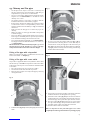
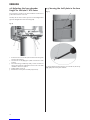
4.6 Adjusting the burn chamber
height for the Jøtul F 470 Series
Any unevenness between the burn chamber and the base/
pedestal/foot must be corrected.
This may also be done to reduce pressure on the draught valves
(prevents draught valves from becoming stiff).
Fig. 24
1. If the base has been mounted, the shelf and the inner plate
must be removed first.
2. Unscrew the screws (A) approx. 4 mm on both sides of the
product.
3. Unscrew B using an Allen key until you feel resistance in
the key. Then turn the adjustment screw to raise the burn
chamber as much as required.
4. Finally, tighten screws A.
5. Refit the base inner plate and shelf (only for base).
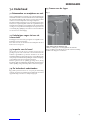
4.7 Securing the shelf plate in the base
Fig. 25
To ensure that the shelf in the base does not fall out, tilt the tip
(Fig. 25 A) of the inner plate outwards.
ENGLISH

17
4.8 Performance check
Always check the control handles once the product has been
assembled. These should move easily and work in a satisfactory
manner.
Fig. 26 - 1
The Jøtul F 470 is equipped with the following operating options:
Air vent (Fig. 26 - 1 A)
Pushed in: Closed
Pulled out completely: Open
If the valve is difficult to pull out, see step 4.6.
Ignition vent (Fig. 26 - 1 B)
Pushed in: Closed
Pulled out completely: Open
If the valve is difficult to pull out, see step 4.6.
Riddling grate (Fig. 26 - 1 B) (same handle as for the ignition vent).
Right-hand handle pulls in and out
Handle (Fig. 26 - 1 C) for door
Opens by pulling the handle all the way out and then raising
the door.
Stack height (Fig. 26 - 1D) for firewood (the firewood must not
cover the holes).
If the weights touch the side plates and the bearings make a
noise when the door is raised, move the side plates out slightly.
See step 4.4.
4.9 Location of approval label
The approval label must always be affixed to the wire and
positioned as illustrated in Fig. 26 - 2 A.
Fig. 26 - 2, Base
Fig. 26 - 2, Pedestal
Fig. 26 - 2, Foot
NB! Note that, on the foot, the approval label A must be pushed
in onto the clip B with the text turned downwards.
ENGLISH

18
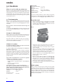
5.0 Daily use
Odours when using the fireplace for the first time
When the fireplace is used for the first time, it may emit an
irritating gas which may smell slightly. This happens because
the paint dries.The gas is not toxic but the room should be
thoroughly ventilated. Let the fire burn with a high draught until
all traces of the gas have disappeared and no smoke or odours
can be detected.
5.1 Operation
NB! If the door handle is shut when the door is in the upper
position, it will be possible for the door to remain in this position
by dropping the door stopper (Fig. 15 A) into the slot at the front.
NB: The door must not be open when the fire is lit.
By loosening the screw (Fig. 15 B) and turning the door stopper
in under the handle, the door will always close unless it is being
held open.
Heating advice
NB: Logs that have been stored outdoors or in a cold room should
be brought indoors 24 hours before use to bring them up to room
temperature.
There are various ways of heating the stove but it is always
important to be careful about what you put in the stove. See the
section on “Wood quality”.
Wood quality
By quality wood we mean most well-known types of wood such
as birch, spruce and pine.
The logs should be dried so that the moisture content is no more
than 20%.
To achieve this, the logs should be cut during the late winter. They
should be split and stacked in a way that ensures good ventilation.
The wood stacks should be covered to protect the logs from rain.
The logs should be brought indoors during early autumn and
stacked/stored for use in the coming winter.
Be especially careful never to use the following materials as fuel
in your fireplace:
• Household rubbish, plastic bags, etc.
• Painted or impregnated timber (which is extremely toxic).
• Laminated wooden planks.
• Driftwood
These may harm the product and are also pollutants.
NB: Never use petrol, paraffin, methylated spirit or similar liquids
to light the fire. You may cause serious injury to yourself and
damage to the product.
Kindling (finely split wood):
Length: approx. 30 cm
Diameter: 2-5 cm
Quantity required each time: 6 - 8 pieces
Wood (split wood):
Recommended length: 20 - 30 cm
Diameter: Approx. 8 cm
Interval for adding wood: Approx. every 45 minutes
Fire size: 1,6 kg (nominal output)
Quantity required each time: 2
Nominal heat output is achieved when the air vent is open
approx. 100% (Fig. 26 A) and the handle for the ignition vent
(Fig. 26 - 1 B) pulled out approx. 1-2 cm.
Initial lighting
• Open the air vent and ignition vent by pulling the handles
(Fig. 26 - 1 A and B) all the way out. (Use a glove or something
similar to protect your hand in case the handles are hot.)
Fig. 27
• Place two logs at the bottom of the burn chamber and pile
the kindling in layers.
• Finally, place a medium-sized log on the top of the pile.
• Place 2 or 3 briquettes or kindling sticks under the top layer
of kindling and light the fire.
• NB: The maximum height of the pile of the wood should
be just below the horizontal holes. The holes must not be
covered.
• Close the ignition vent (Fig. 26 - 1 B) when the wood has
caught fire properly and is burning well.
• Close the door.
• You can then regulate the rate of combustion to give the heat
you want by adjusting the air vent (fig. 26- 1 A).
• Check that the afterburning (secondary combustion) starts.
This is best indicated by yellow, flickering flames in front of
the holes under the baffle.
• If the air flow is normal you will be able to shut the door and
the fire will take care of itself.
Adding firewood
Stoke the stove frequently but only add small amounts of fuel at
a time. If the stove is filled too full, the heat created may cause
extreme stress in the chimney. Add fuel to the fire in moderation.
Avoid smouldering fires as this produces the most pollution.
The fire is best when it is burning well and the smoke from the
chimney is almost invisible.
5.2 Danger of overheating
The fireplace must never be used in a manner that
causes overheating
Overheating occurs when there is too much fuel and/or too much
air so that too much heat develops. A sure sign of overheating is
when parts of the fireplace glow red. If this happens, reduce the
air vent opening immediately.
Seek professional advice if you suspect that the chimney is not
drawing properly (too much/too little draught). For further
information, see «4.0 Installation» (Chimney and flue pipe).
ENGLISH

19
5.3 Ash removal
• The Jøtul F 470 has an ash pan that makes it easy to remove
the ash.
• Only remove ash when the fireplace is cold.
• Scrape the ash through the grate in the inner bottom and
down into the ash pan. Use a glove or something similar to
protect your hand. Take hold of the handle of the ash pan and
lift out the ash. Make sure that the ash pan never gets so full
that it prevents the ash from falling through the grate and
down into the pan.
• Make sure that the ash pan is pushed all the way in before
closing the door.
5.4 Cleaning the inside of the glass
Fig. 28
1. Remove all ash from the burn chamber.
2. Raise the door and remove the ash retainer (Fig. 28 A). Hold
the door semi-open as illustrated.
3. Then clean the lower section of the glass by putting your
hand in under the door and behind the glass.
4. Open the door fully and secure it in the upper position (Fig. 15).
5. Clean the upper section of the glass.
Good advice! Normal cleaning – take a piece of kitchen paper
and dampen it with warm water. Dab it on some ash from the
burn chamber then rub the glass with the paper. Wipe clean with
fresh water. Dry well. If the glass needs cleaning more thoroughly,
use a detergent for glass (follow the manufacturer’s instructions
on the bottle).
6.0 Servicing
Warning! Any unauthorised changes to the product are illegal!
Only original spare parts may be used!
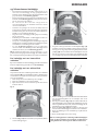
6.1 Service/replacing parts in the burn
chamber
NB: Use tools with great care! The vermiculite plates may be
damaged if treated roughly.
Fig. 29
1. Lift the ash retainer (Fig. 29 A) up and out.
2. Pull the baffles (Fig. 29 B) forward, lift slightly, turn and lower
them.
3. Be sure to note the position of the exhaust deflectors (Fig. 29 C)
before removing them to ensure that they can be fitted back
into exactly the right places. Take hold of the pin (Fig. 29 D) on
the underside of the exhaust deflectors. Lift them up slightly
and then sideways before lowering them.
4. Lift the front side burn plates (Fig. 29 E) up and out.
5. Take hold of the upper part of the back side burn plates (Fig. 29 F)
and turn them in towards the middle of the burn chamber.
Then pull them out.
6. Pull out the back burn plate (Fig. 29 G). When fitting it back
into place, check that the gasket on the back burn plate is
securely attached.
7. Lift out the riddling grate (Fig. 29 H) (can be done first when
it needs replacing). Make sure that the slot on the riddling
grate is against the bar under the inner bottom plate when
it is fitted back into place.
8. Lift and move the inner bottom plate (Fig. 29 I) out.
9. Hold the upper air duct (Fig. 29 J) up at the front edge while
loosening the screw (Fig. 29 K). Use a ratchet with a 13 mm
socket and an extension piece. Tilt the air duct downwards
when the screw is loose. This can also be done after point 5.
There are gaskets at both the front and back of the air duct.
Glue new gaskets on before fitting it back into place.
10. When refitting, follow the same procedure in reverse order.
ENGLISH

20
6.2 Replacing the side plates
Aluminium or glass sides
1. Undo the screws (Fig.19 A) holding the brackets on the top.
Lift the brackets up and remove the side plates. If the stove
has a smoke outlet on the top, the top plate can be raised and
turned to make it easier to get at the screws (A).
2. If necessary, insert new sides as described in Chapter 4.4.
Cast iron and soapstone side panels
1. Remove the screws (Fig. 6 A) that are underneath holding the
sides in place at the bottom.
2. Loosen the screws (Fig. 19 A) holding the sides on the top.
Lift off the sides. If the stove has a smoke outlet on the top,
the top plate can be raised and turned to make it easier to
get at the screws (A).
3. If necessary, insert new sides as described in Chapter 4.4.
6.3 Replacing the weights
1. Close the door.
2. Remove the side plates as described in the previous section.
3. Hold up the weights while loosening the screws (Fig. 13 A)
and lift the weights off.
4. NB! The weights are heavy and must be held firmly during
this procedure.
5. When refitting, follow the procedure as described in Chapter
4.2 “Mounting the weights”.
6.4 Replacing glass and gaskets in the
door
Fig. 30 - I
1. Remove the side plates as described in Chapter 6.2.
2. Remove the weights as described in Chapter 6.3.
3. Unscrew the wire guides (Fig. 30 - I, A) on each side of the
stove.
Fig. 30 - II
4. Open the handle (Fig. 30 - II, B) but do not raise the door.
5. Remove the four screws (Fig. 30 - II, C) and the washers holding
the door in place in the bearing holder. NB: Ask someone to
hold the door while doing this so that it does not fall down.
Remove the door and lay it, with its outside facing down, on
a soft, clean blanket or mat.
ENGLISH
La pagina si sta caricando...
La pagina si sta caricando...
La pagina si sta caricando...
La pagina si sta caricando...
La pagina si sta caricando...
La pagina si sta caricando...
La pagina si sta caricando...
La pagina si sta caricando...
La pagina si sta caricando...
La pagina si sta caricando...
La pagina si sta caricando...
La pagina si sta caricando...
La pagina si sta caricando...
La pagina si sta caricando...
La pagina si sta caricando...
La pagina si sta caricando...
La pagina si sta caricando...
La pagina si sta caricando...
La pagina si sta caricando...
La pagina si sta caricando...
La pagina si sta caricando...
La pagina si sta caricando...
La pagina si sta caricando...
La pagina si sta caricando...
La pagina si sta caricando...
La pagina si sta caricando...
La pagina si sta caricando...
La pagina si sta caricando...
La pagina si sta caricando...
La pagina si sta caricando...
La pagina si sta caricando...
La pagina si sta caricando...
La pagina si sta caricando...
La pagina si sta caricando...
La pagina si sta caricando...
La pagina si sta caricando...
La pagina si sta caricando...
La pagina si sta caricando...
La pagina si sta caricando...
La pagina si sta caricando...
La pagina si sta caricando...
La pagina si sta caricando...
La pagina si sta caricando...
La pagina si sta caricando...
La pagina si sta caricando...
La pagina si sta caricando...
La pagina si sta caricando...
La pagina si sta caricando...
La pagina si sta caricando...
La pagina si sta caricando...
La pagina si sta caricando...
La pagina si sta caricando...
La pagina si sta caricando...
La pagina si sta caricando...
La pagina si sta caricando...
La pagina si sta caricando...
La pagina si sta caricando...
La pagina si sta caricando...
La pagina si sta caricando...
La pagina si sta caricando...
La pagina si sta caricando...
La pagina si sta caricando...
La pagina si sta caricando...
La pagina si sta caricando...
La pagina si sta caricando...
La pagina si sta caricando...
La pagina si sta caricando...
La pagina si sta caricando...
La pagina si sta caricando...
La pagina si sta caricando...
La pagina si sta caricando...
La pagina si sta caricando...
La pagina si sta caricando...
La pagina si sta caricando...
La pagina si sta caricando...
La pagina si sta caricando...
La pagina si sta caricando...
La pagina si sta caricando...
La pagina si sta caricando...
La pagina si sta caricando...
La pagina si sta caricando...
La pagina si sta caricando...
La pagina si sta caricando...
La pagina si sta caricando...
La pagina si sta caricando...
La pagina si sta caricando...
La pagina si sta caricando...
La pagina si sta caricando...
La pagina si sta caricando...
La pagina si sta caricando...
La pagina si sta caricando...
La pagina si sta caricando...
La pagina si sta caricando...
La pagina si sta caricando...
La pagina si sta caricando...
La pagina si sta caricando...
La pagina si sta caricando...
La pagina si sta caricando...
La pagina si sta caricando...
La pagina si sta caricando...
-
 1
1
-
 2
2
-
 3
3
-
 4
4
-
 5
5
-
 6
6
-
 7
7
-
 8
8
-
 9
9
-
 10
10
-
 11
11
-
 12
12
-
 13
13
-
 14
14
-
 15
15
-
 16
16
-
 17
17
-
 18
18
-
 19
19
-
 20
20
-
 21
21
-
 22
22
-
 23
23
-
 24
24
-
 25
25
-
 26
26
-
 27
27
-
 28
28
-
 29
29
-
 30
30
-
 31
31
-
 32
32
-
 33
33
-
 34
34
-
 35
35
-
 36
36
-
 37
37
-
 38
38
-
 39
39
-
 40
40
-
 41
41
-
 42
42
-
 43
43
-
 44
44
-
 45
45
-
 46
46
-
 47
47
-
 48
48
-
 49
49
-
 50
50
-
 51
51
-
 52
52
-
 53
53
-
 54
54
-
 55
55
-
 56
56
-
 57
57
-
 58
58
-
 59
59
-
 60
60
-
 61
61
-
 62
62
-
 63
63
-
 64
64
-
 65
65
-
 66
66
-
 67
67
-
 68
68
-
 69
69
-
 70
70
-
 71
71
-
 72
72
-
 73
73
-
 74
74
-
 75
75
-
 76
76
-
 77
77
-
 78
78
-
 79
79
-
 80
80
-
 81
81
-
 82
82
-
 83
83
-
 84
84
-
 85
85
-
 86
86
-
 87
87
-
 88
88
-
 89
89
-
 90
90
-
 91
91
-
 92
92
-
 93
93
-
 94
94
-
 95
95
-
 96
96
-
 97
97
-
 98
98
-
 99
99
-
 100
100
-
 101
101
-
 102
102
-
 103
103
-
 104
104
-
 105
105
-
 106
106
-
 107
107
-
 108
108
-
 109
109
-
 110
110
-
 111
111
-
 112
112
-
 113
113
-
 114
114
-
 115
115
-
 116
116
-
 117
117
-
 118
118
-
 119
119
-
 120
120


Jøtul F 475 Installation And Operating Istructions
- Categoria
- Camini
- Tipo
- Installation And Operating Istructions
in altre lingue
- English: Jøtul F 475
- français: Jøtul F 475
- español: Jøtul F 475
Documenti correlati
-
Jøtul F 375 Manuale del proprietario
-
-
-
-
-
-
-