Jøtul F 400 Installation And Operating Instructions Manual
- Categoria
- Stufe
- Tipo
- Installation And Operating Instructions Manual

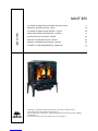
Jøtul F 400
Installation and Operating Instructions for USA/Canada 2
Montering- og bruksanvisning - Norsk 20
Installation and Operating Instructions - English 26
Manuel d'installation et d'utilisation - Francaise 31
Instrucciones para instalación - Español 36
Manuale di installazione ed uso - Italiano 42
Montage- und Bedienungsanleitung - Deutsch 47
Installatie- en montagehandleiding - Nederlands 53
Jøtul F 400
Monterings-. og bruksanvisningen må oppbevares under hele produktets levetid.
These instructions must be kept for future references.
Wir empfehlen Ihnen, die Montage- und Bedienungsanleitung für spätere Zwecke sorgfältig
aufzubewahren.
Ce document doit être conservé pendant toute la vie de l'appareil.

2
Installation and Operating Instructions for USA
Installation et fonctionnement pour Canada
Safety notice: If this solid fuel room heater is not properly installed, a house fire may result. For your safety, follow
the installation directions. Contact your local building or fire officials about restrictions and installation inspection
requirements in your area. Kindly save these instructions for future references.
Avis de sécurité: Une installation non appropriée de ce poêle de chauffage risque de provoquer un incendie. Assurez
votre sécurité en respectant les directives d`installation suivantes. Consultez les autorités locales du bâtiment ou de
la prévention des incendies au sujet des restrictions et exigences relatives aux inspections d`installations dans votre
région.
Tested and listed by ITS Intertek Testing Services, Middleton, Wisconsin.
Tested to U.S. Standards: ANSI/UL 1482, Canadian Standards: CAN/ULC-S627-M93
Standards
The F 400 Castine woodstove has been tested and listed
to;
U.S. Standards: ANSI/UL 737 and ANSI/UL 1482.
Canadian Standards: CAN/ULC-S627-M93
Tests performed by:
ITS, Intertek Testing Services, Middleton, WI
Manufactured by:
Jøtul A.S.A., P.O. Box 1411, N-1602 Fredrikstad, Norway
Distributed by:
Jøtul North America, P.O. Box 1157
400 Riverside Street - Portland, ME 04104
This heater meets the U.S. Environment Protection
Agency’s Emissions limits for wood heaters manufactured
and sold after July 1, 1990.
Under specific test conditions, this heater has shown heat
output at rates ranging from 12,000 to 35,000 BTU’s per
hour.
Important: The Jøtul F 400 Castine woodstove is only
listed to burn wood. Do not burn any other fuels.
Read this entire manual before you install and use your
new room heater.
Save these instructions and make them available to
anyone using or servicing the stove.
Jøtul F 400 Castine Woodstove
When installing, operating and maintaining your Jøtul F
400 Castine woodstove, follow the guidelines presented
in these instructions, and make them available to anyone
using or servicing the stove.
A number of areas require a building permit to install a
solid fuel burning appliance.
In the U.S., the National Fire Protection Association’s Code,
NFPA 211, Standards for Chimneys, Fireplaces, Vents and Solid
Fuel Burning Appliances, or similar regulations, may apply
to the installation of a solid fuel burning appliance in your
area.
In Canada, the guideline is established by the CSA
Standard, CAN/CSA-B365-M93
,
Installation Code for Solid-
Fuel-Burning Appliances and Equipment.
Always consult your local building inspector or authority
having jurisdiction to determine what regulations apply
in your area.
Do not connect to any air distribution duct or system.
USA
Stoves and fireplaces must be installed to conform to local and national building regulations. Before preparing for the installation of the appliance,
it is important that the instructions issued with the unit are carefully read and strictly adhered to. Jøtul pursue a policy of constant product development.
Products supplied may therefore differ in specification, colour and type of accessories from those illustrated and described in the brochure.
Jøtul vise sans cesse à améliorer ses produits. C’est pourquoi, il se réserve le droit de modifier les spcifications, couleurs etéquipement sans avis
prélable.

3
Table of contents
Standards and Safety Notices
Jøtul F 400 Castine Woodstove ................................................. 2
Notices ..............................................................................................3
Installation
Installing the flue collar .............................................................. 4
Stove pipe chimney connector .................................................4
Chimney Requirements
Masonry Chimneys .......................................................................4
Prefabricated Chimneys .............................................................. 5
Chimney height.............................................................................. 5
Wall pass-throughs....................................................................... 5
Connecting to the Chimney
Masonry Chimney ......................................................................... 6
Hearthmount/Fireplaces ............................................................ 6
Prefabricated Chimney ................................................................ 6
Clearances to combustibles
Floor protection ............................................................................. 6
Clearances to walls and ceilings .............................................. 7
Using shields to reduce clearances ......................................... 7
Alcove installations ....................................................................... 7
Mobile home installations ..........................7
Operation
Do not burn .....................................................................................8
Controls on the F 400 Castine ................................................... 8
Breaking in your Stove ................................................................. 8
Starting and Maintaining a fire................................................ 8
Adding fuel ...................................................................................... 9
Formation of Creosote................................................................. 9
Maintenance
Ash Removal .................................................................................... 9
Glass Care ........................................................................................9
General Maintenance .................................................................. 10
Gaskets ............................................................................................. 10
Accessories
Firescreen ......................................................................................... 10
Outside Air Kit ................................................................................ 10
Floor Bracket Kit ............................................................................ 11
Rear Heatshield .............................................................................. 11
Bottom Heatshield........................................................................ 11
Stove -Top Thermometer ............................................................ 11
Figures - drawings
Figures - drawings ................................................................. 12– 17
Parts list ............................................................................................ 18
Appendix A
Alternate floor protection ..........................................................18
Notices
Do not use chemicals or fluids to start the fire. Do not burn
garbage or flammable fluids.
If this room heater is not properly installed, a house fire
may result. To reduce the risk of fire, follow the installation
instructions.
Failure to follow these instructions may
result in property damage, bodily injury, or even death.
Jøtul recommends that you have your new Jøtul F 400
Castine installed by a professional installer of solid fuel
burning appliances.
Extremely hot while in operation! Keep children, clothing
and furniture away. Contact may cause skin burns.
Avoid creating a low pressure condition in the room where
the stove is operating. Operating an exhaust fan or a
clothes dryer could create a low pressure area, causing
poisonous gases to come out of the stove into the room.
You can prevent low pressure conditions by providing
adequate combustion air within 24” but not closer than
12” from the stove. Or, simply install the optional outside
air manifold system, which allows the direct connection
of air from outside the house to the stove.
Do not use chemicals or fluids to start the fire. Some fuels
will, during combustion, separate carbon monoxide and
generate it in the burn chamber. Carbon monoxide is toxic,
so please follow the guidelines in this manual for proper
operation of your Jøtul F 400 Castine.
If you for some reason experience smoke “roll-out” from
the stove, it may activate smoke detectors if installed in
the house.
Installation
If this solid fuel room heater is not properly installed a
house fire may result. For your safety, follow the
installation directions. Contact the local building or fire
officials about restrictions and installation inspection
requirements in your area.
Reminder: Your local officials have final authority in
determining if a proposed installation is acceptable. Any
requirement, that is requested by the local authority
having jurisdiction, that is not specifically addressed in
THIS manual, defaults to NFPA 211, and local codes in the
U.S. or in Canada, CAN/CSA-B365-M and local codes.
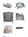
Mounting before installation
The F 400 Castine is sold in many countries with varying
USA

4
demands on fireplaces. Therefore, together with the flue
collar, gasketing and hardware inside the stove, it is
equipped with an extra inspection cover, marked Europe,
which may be throwned away, and a bottom heat shield.
The heat shield is to be used in alcove installations.
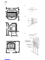
Installing the flue collar
To install the flue collar in the top or rear exit position
remove the tape from the gasketing and adhere to the
groove on the back of the stove around the flue opening.
Place the flue collar on the stove in the top or rear exit
position and secure with the nut, bolt and washer. The
nut and washer are placed on the inside of the stove.
Stove pipe chimney connector
The chimney connector is a single walled pipe used to
connect the stove to the chimney. For use with the F 400
Castine the chimney connector must be 6” in diameter,
with a minimum thickness of 24 gauge black steel.
Aluminum and Galvanized steel pipe is not acceptable for
use with the F400 Castine. These materials cannot
withstand the extreme temperatures of a wood fire and
can give off toxic fumes when heated.
Do not use the connector pipe as a chimney.
Each chimney connector or stove pipe section must be
installed to the stove flue collar and to each other with
the male (crimped) end toward the stove. See figure 2.
This prevents any amount of condensed or liquid creosote
from running down the outside of the pipe or the stove
top. All joints, including the flue collar connection must
be secured with three sheet metal screws to ensure that
the sections do not separate.
For the best performance the chimney connector should
be as short and direct as possible, with no more than two
90° elbows. The maximum horizontal run is 36” and a
recommended total length of stove pipe should not
exceed 10 feet. Always slope horizontal runs upward ¼”
per foot toward the chimney.
No part of the chimney connector may pass through an
attic or roof space, closet or other concealed space, or
through a floor or ceiling. All sections of the chimney
connectors must be accessible for cleaning. Where
passage through a wall or partition of combustible
construction is desired, the installation must conform with
NFPA 211 or CAN/CSA-B365M, and is also addressed in this
manual.
Do not connect this unit to a chimney flue servicing
another appliance.
Chimney requirements
There are two types of chimneys suitable for the F 400
Castine:
1. A code-approved masonry chimney with a flue liner.
2. A prefabricated chimney complying with the
requirements for Type HT (2100°F) chimneys per UL 103
or ULC S629.
The chimney size should not be less than the cross-
sectional area of the flue collar, and not more than three
times greater than the cross-sectional area of the flue
collar.
When selecting a chimney type and the location for the
chimney in the house, keep this in mind: It is the chimney
that makes the stove work, not the stove that makes the
chimney work. This is because a chimney actually creates
a suction, called “draft” which pulls air through the stove.
Several factors affect draft: Chimney height, cross-
sectional area (size), and temperature of the chimney, as
well as the proximity of surrounding trees or buildings.
As a result, a short masonry chimney on the exterior of a
house will give the poorest performance. This is because
it can be very difficult to warm the chimney thereby
creating inadequate draft. In extremely cold northern
areas it may be necessary to reline the chimney or extend
its height to help establish draft.
Oppositely, a tall masonry chimney inside the house is
easier to keep warm and will perform the best.
The following guidelines give the necessary chimney
requirements based on the national code (ANSI-NFPA
211for the US. And CSA CAN-B365-M for Canada). However,
many local codes differ from the national code to take into
account climate, altitude, or other factors.
Notice: It is important that you check with your local
building officials to find out what codes apply in your area
before installing your new F 400 Castine.
Remember: Your local inspector(s) have the final authority
in approving your installation. It is always best to consult
them prior to the installation.
Do not connect this stove to any air distribution duct or
system.
Masonry Chimneys
When installing the F 400 Castine into a masonry chimney
you must conform to all of the following guidelines:
•The masonry chimney must have a fireclay liner or
equivalent, with a minimum thickness of 5/8” and
USA

5
must be installed with refractory mortar. There must
be at least ½” air space between the flue liner and
chimney wall.
•The fireclay flue liner must have a nominal size of 8” X
8”, and should not be larger than 8”X 12”. If a round
fireclay liner is to be used it must have a minimum
inside diameter of 6” and not larger than 8” in
diameter. If a chimney with larger dimensions is to be
used, it should be relined with an appropriate liner that
is code approved.
•The masonry wall of the chimney, if brick or modular
block, must be a minimum of 4” nominal thickness. A
mountain or rubble stone wall must be at least 12”
thick.
•A newly-built chimney must conform to local codes
and in their absence must recognize national
regulations.
•When using an existing chimney, it must be inspected
by a professional licensed chimney sweep, fire official,
or code officer, to ensure that the chimney is in proper
working order.
•No other appliance can be vented into the same flue.
•An airtight clean-out door should be located at the
base of the chimney.
Prefabricated Chimneys
If a prefabricated metal chimney is to be used it must be a
chimney type that is tested and listed for use with solid
fuel burning appliances. High Temperature (HT) Chimney
Standard UL 103 for the U.S. and High Temperature
Standard ULC S-629 for Canada.
The manufacturer’s installation instructions must be
followed precisely. Always maintain the proper clearance
to combustibles as established by the pipe manufacturer.
This clearance is usually a minimum of 2”, although it may
vary by manufacturer or for certain chimney components.
Chimney Height
Whether a masonry chimney or prefabricated metal
chimney is used it must be the required height above the
roof line.
The requirement is:
The chimney must be at least 3 feet higher than the
highest point where it passes through the roof and at least
2 feet higher than the highest part of the roof or structure
that is within 10 feet of the chimney, measured
horizontally. See figure 3.
Chimneys shorter than 14 feet may not provide adequate
draft. This could result in smoke spilling into the room
from the stove when loading the stove, or when the door
is open. In addition, inadequate draft can cause back
puffing, which is a build up of gases inside the firebox.
Other times, chimney height can create excessive draft
which can cause high stove temperatures and short burn
times. Excessive drafts can be corrected by installing a
butterfly damper. If you suspect you have a draft problem,
consult your dealer.
Wall Pass Throughs
When your installation unavoidably requires the chimney
connector to pass through a combustible wall to reach the
chimney, always consult your local building officials, and
be sure any materials to be used have been tested and
listed for wall pass-throughs.
In the U.S.
The National Fire Protection Association’s publication,
NFPA 211, Standard for Chimneys, Fireplaces, Vents and Solid
Fuel Burning Appliances permits four methods for passing
through a combustible wall. Before proceeding with any
method be sure to consult with your local building officials
to discuss any local code requirements.
Common Method
When passing through a combustible wall to a masonry
chimney this method requires the removal of all
combustible materials from at least 12” around the
chimney connectors proposed location. With a 6” round
liner the minimum area required would be 31” x 31” square.
The space is then filled with at least 12” of brick around a
fireclay liner. Remember, the liner must be ASTM C35 or
equivalent, with a minimum wall thickness of 5/8”.
It is important to remember to locate the pass-through
at least 18” from the ceiling for proper clearance to
combustibles.
It will be necessary to cut wall studs, install headers, and
construct a sill frame to maintain the proper dimensions
and to support the weight of the brick.
The bricks must be solid brick with a minimum of
3 ½ “ thick (4” nominal).
Refractory mortar must be used at the junction of the
chimney and the pass-through liner. The pass-through
liner must not penetrate the chimney liner beyond the
inner surface of the chimney liner. Use extreme care when
constructing the hole in the chimney liner, the tiles can
shatter easily. See figure 3.
In Canada
The Canada the standard has been established by the
Canadian Standard Association. The installation must
conform to CAN/CSA-B365, Installation Code for Solid Fuel
Burning Appliances and Equipment.
Before proceeding be sure to consult your local building
inspector.
USA

6
Common Method
This method requires the removal of all combustible
materials from at least 18” (457mm) around the chimney
connector’s proposed location. With a 6” round liner the
minimum area required would be 43” x 43” square.
It is important to remember to locate the pass-through
at least 18” from the ceiling to maintain the proper
clearance to combustibles.
The space that is cleared of combustible materials must
then remain empty. Sheet metal panels can then be used
to cover the area. However, when using a panel on both
sides of the wall each cover must be installed on
noncombustible spacers at least 1” from the wall. If one
panel of sheet metal is to be used it may be installed flush
to the wall.
See section 5.3.1 and 5.3.2 of CAN/CSA - B365-M91.
Consult your local building inspector, authorized Jøtul
Dealer, NFPA 211 in the U.S. or CAN/CSA-B635 in Canada
for other approved wall pass-through methods.
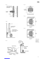
Connecting to the chimney
Masonry Chimney
When installing a Jøtul F 400 Castine into a masonry
chimney through a “thimble”(the opening through the
chimney wall to the flue), the thimble must be lined with
ceramic tile or metal and be securely cemented in place.
The chimney connector/stove pipe must slide completely
inside the thimble to the inner surface or the flue liner. It
may be necessary to make use of a thimble sleeve (a pipe
with a slightly smaller diameter than standard stove pipe).
This special pipe can be easily installed into a thimble. See
figure 4.
Make sure the connector pipe or thimble sleeve does not
protrude into the flue liner, thereby restricting the area
the smoke has to flow through. This bottle-neck will have
a negative affect on the chimney system.
The chimney connector should be sealed at the thimble
with refractory cement and the stove pipe leading to the
stove should have a minimum of three screws.
Do not connect this stove to a chimney flue servicing
another appliance of any kind.
Hearth-mount into a Masonry
Fireplace
The F 400 Castine may be installed into a masonry
fireplace provided the height of the opening is a minimum
of 29 1/2”. If necessary, the short leg package reduces the
stove’s height by 2 1/4”.
When installing the stove into a masonry fireplace, code
requires that the fireplace damper plate be removed or
securely fixed in the open position. A connector pipe must
then extend from the stove’s flue exit through the damper
area of the fireplace and into the chimney tile liner. See
figure 5.
The inside area of the flue liner must not be less than the
area of the stove’s flue exit, and cannot be more than three
times greater than the cross sectional area of the stove’s
flue exit.
If the chimney liner is too large to accommodate the stove,
an approved relining system must be installed to resize
the flue.
A new sheet metal damper block-off plate must be
installed around the connector pipe at the damper frame
and sealed with the proper sealant (usually High-Temp
Silicone).
Fireplace installation must also observe the proper
clearances to surrounding trim and mantels (addressed
in clearance section of this manual). In addition, fireplace
installations must also adhere to the floor protection
guidelines specified in the following section.
Prefabricated Chimneys
When installing the F 400 Castine to a prefabricated metal
chimney always follow the pipe manufacturer’s
instructions and be sure to use the components that are
required. This usually includes some type of “smoke pipe
adapter” that is secured to the bottom section of the metal
chimney and allows the chimney pipe to be secured to it
with three sheet metal screws. See figures 6 and 7.
Clearances to combustibles
Floor Protection
(In the U.S. and Canada)
The F 400 Castine requires any one of the following three
forms of hearth protection:
1. Any UL, ULC or WH listed hearth board. (No bottom
heatshield required).
2 Any non-combustible material that has a minimum
R- value of 2.0. (No bottom heatshield required.)
USA

7
3. Any non-combustible material with the use of the
stove’s bottom heatshield.
All forms of protection must be a non-combustible surface
extending a minimum of 18” (460mm) in front of the
stove. And 8” (200mm) from the sides and back of the
stove (measured from side and back panels).
This will result in a minimum floor protection of 42” W X
44”D. See figure 8.
In a rear vent installation the floor protection must also
extend under the stove pipe a minimum of 2” (50mm)
beyond either side of the pipe. See figure 8.
When constructing a new hearth or floor pad, consult
appendix a at the back of this manual for alternate
materials and methods.
Clearances to walls and ceilings
The following clearances have been tested to UL and ULC
standards and are the minimum clearances specifically
established for the Jøtul F 400 Castine.
The following diagrams give the required clearances you
must maintain when installing the F 400 Castine near
combustible surfaces.
A combustible surface is anything that can burn (i.e. sheet
rock, wall paper, wood, fabrics etc.). These surfaces are not
limited to those that are visible and also include materials
that are behind non-combustible materials.
If you are not sure of the combustible nature of a material,
consult your local fire officials.
Remember: “Fire Resistant” materials are considered
combustible; they are difficult to ignite, but will burn. Also
“Fire-rated” sheet rock is also considered combustible.
Contact your local building officials about restrictions and
installation requirements in your area.
See pages 12- 13 for complete clearance requirements and
diagrams.
Using Shields to Reduce Clearances
Pipe shields: When using listed pipe shields to reduce the
connector clearance to combustibles, it must start 1” above
the lowest exposed point of the connect pipe and extend
vertically a minimum of 25” above the top surface of the
stove.
Double wall pipe: Listed double wall pipe is an acceptable
alternative to connector pipe heatshields.
Wall-mounted protection: When reducing clearances
through the use of wall mounted protection:
In the U.S. refer to NFPA 211, Standard for Chimneys,
Fireplaces, Vents and Solid Fuel Burning Appliances, for
acceptable materials, proper sizing and construction
guidelines.
In Canada, refer to CAN/CSA-B365, Installation Code for
Solid-Fuel Burning Appliances and Equipment, also for
acceptable materials, proper sizing and construction
guidelines.
Stove Mounted Heatshield: A stove rear heatshield has
been specifically designed for the F 400 Castine.
In the U.S. and Canada the rear heatshield part number
is # 154911. No other heat shield may be used.
NOTICE: Accessories for woodstoves for clearance
reduction have been developed by many manufacturers.
If not following the methods of the installation codes, be
sure that any accessory you choose has been tested by an
independent laboratory and carries the laboratory’s
testing mark. Make sure to follow all of the manufacturer’s
instructions.
Always contact your local building inspector or fire officials
about restriction and requirements in your area. Reminder,
it is the local officials who have final authority in the
installations approval.
Alcove
The F 400 Castine can be installed in an ALCOVE situation
provided: See figures 9 and 10.
1. The stove must be installed with listed double wall
pipe.
2. In a PROTECTED alcove installation both side walls
and rear wall must be protected per NFPA 211 or CAN/
CSA-B365. The wall protection must be elevated 1”
from the floor and at least 1” off the combustible
wall to allow for an air-flow.
3. The height of the wall protection including the bottom
air space must be 48”.
4. The Bottom heatshield is required in all Alcove
installations.
5. ALCOVE floor protection must be: a UL/ULC or WHI
listed hearth pad or a non combustible material with
a minimum R value of 2.0.
6. Minimum ceiling height in an unprotected installation,
off the top of the stove is 58” (1475mm). The minimum
ceiling height off the top of the stove in a protected
ceiling installation is 36” (915mm).
Mobile home installations
The F 400 Castine has been approved for use in mobile
homes in the U.S. and Canada, provided:
USA

8
1. The stove is secured to the floor or the mobile home.
Floor mounting kit #750304.
2. The stove is provided outside air for combustion.
Outside Air kit #154335(see page 16 for more details).
3. Must be installed in accordance to 24CRR, Part 3280
(HUD).
As always consult with your local building inspector or fire
officials about restrictions and requirements in your area,
prior to installing the stove.
WARNING: Do not install in a bedroom/sleeping room. The
structural integrity of the mobile home’s floor, wall,
ceiling/roof must be maintained.
Operation
Before building a fire in your new F 400 Castine, please
read the following section carefully and completely.
Do not burn
First this stove is designed to burn natural wood only,
wood that has been air-dried for a period of 6 to 14 months
will provide the cleanest most efficient heat.
Do not burn:
•Coal •Treated or painted wood
•Garbage •Chemical Chimney cleaners
•Cardboard •Colored paper
•Solvents •Any synthetic fuel or logs
The burning of any of these materials can result in the
release of toxic fumes. Never use gasoline, gasoline-type
lantern fuel, kerosene, charcoal lighter fluid, or similar
liquids to start or “freshen-up” the fire. Always keep such
liquids away from the heater at all times.
IMPORTANT: Never build or allow the fire to rest directly
on the glass. The logs should always be spaced at least
one inch from the glass to allow for proper air flow within
the stove.
Controls on the Jøtul F 400 Castine
A single air control lever controls the burn time and heat
output of the stove. This primary air control lever is located
on the front of the stove directly above the ash lip. The
primary air lever, controls the amount of air that enters
the stove for combustion.
When first starting or reviving the fire: the primary control
lever should be at the far right position, which allows the
maximum amount of air into the stove. The more air
entering the stove the hotter the fire the shorter the burn
time. Moving the lever to the left reduces the air-flow into
the stove which prolongs the fire at a lower heat output.
See figure 11.
Breaking in your new stove
Your new F 400 Castine is constructed of cast iron and
stove furnace cement. This type of construction requires
the stove to be “broken-in” gradually so that heat
expansion does not occur too quickly and cause damage.
Complete the following steps for the proper break-in
procedure for the F 400 Castine:
1. Light a small fire, newspaper and kindling only, only
allow the stove to reach a maximum surface
temperature of 200°. Burn for approximately 1 hour.
2. Allow stove to cool to room temperature.
3. Light a second fire, allowing the stove to reach a
maximum temperature of 300° for 1 hour.
4. Cool the stove to room temperature.
5. Light a third fire and gradually allow the stove to reach
a surface temperature of 400°
6. Cool stove to room temperature. This completes the
“break-in” procedure.
To monitor the stove’s temperature, Jøtul recommends the
use of a magnetic stove-top thermometer, placed directly
on the corner of the stove’s top plate.
Never allow the stove to exceed a 400° surface
temperature during any “break-in fire” with the exception
of the last “break-in” fire.
Note: It is normal for a new painted stove to emit an odor
and even smoke during its first several fires. This is caused
by the seasoning of the high temperature paint and will
diminish with each fire and will eventually disappear.
Opening a window or door to provide additional
ventilation will reduce the odor as this process takes its
course.
Starting and maintaining a fire
Burn only solid wood directly on the bottom grate of the
stove, do not elevate the fire in any way.
• The ash pan door on the stove must always be securely
closed when the stove is in operation.
• Burning the stove with the ash pan open will over-fire
the stove and cause interior damage.
With the primary air control lever in the full open position,
start with several sheets of crumbled newspaper placed
directly on the grate. On top of the newspaper, place
several pieces of small dry kindling (approx. 1” in diameter)
with two to three larger logs (approx. 3” to 5” in diameter)
on top.
Light the fire and close the door, slowly building the fire
by adding larger and larger logs. Be sure to follow the
break-in procedure before creating a fire that will damage
the stove.
Once the stove has reached a surface temperature range
USA

9
of between 400° and 600°, adjust the primary air control
lever as necessary to generate the heat output and burn
time desired.
Jøtul recommends the use of a magnetic stove top
thermometer to monitor the surface temperature of the
stove. The optimum surface temperature range for the
most efficient burn is between 400° and 600°.
See figure 12 -page 16 for the optimum locations of a stove-
top thermometer.
Important: Never overfire the stove. If any part of the
stove or chimney glows, you are overfiring, and a house
fire or serious damage to the stove or chimney could result.
Immediately close down the air control if you notice this
condition.
Adding fuel
When reloading the stove while it is still hot and a bed of
hot embers still exist, follow this reloading procedure:
•Always wear gloves when tending to the stove.
•Push the air control lever to the full open position (far
right).
•Wait a few seconds before opening the door.
•Use a stove tool or poker to distribute the hot embers
equally around the firebox.
•Load the fuel, usually with smaller logs first.
•Close the door, be sure to latch the door tightly.
•Wait 5 – 10 minutes before adjusting the primary air
to the desired heat output setting.
•(If you have at least a 2” thick ember bed when
reloading, it may be possible to close the door and
immediately adjust the air control setting).
The formation of creosote
When wood is burned slowly and at low temperatures, it
produces tar and other organic vapors, which combine
with moisture to form creosote. The slow moving smoke
carries the creosote vapors, which condense in the cooler
chimney flues, and this creosote then sticks to the chimney
walls.
The creosote that accumulates in the chimney is highly
flammable and is the fuel of chimney fires. To prevent
chimney fires it is important to have the chimney and
chimney connector pipe inspected and/or cleaned semi-
annually. A qualified chimney sweep or other authorized
service person can provide this service.
It is also important to remember that chimney size,
temperature and height all affect draft which in turn
affects the formation of creosote. Be sure to follow the
installation and operation guidelines established in this
manual.
Maintenance
Ash removal
Of course, for your protection always wear safety gloves
when handling the ash pan.
Ash removal will be required periodically depending on
how frequently the stove is used. Conveniently, the F 400
Castine is equipped with an ash pan assembly for easy
ash removal, without the need for opening the front doors.
The ash pan door is located under the front ash lip of the
stove. To open the ash door place the receptacle end of
your specially designed ash tool onto the square fitting of
the ash door latch. Rotate the door counterclockwise to
unlatch the door and clockwise to latch the door.
With a gloved hand grasp the ash pan handle and remove
the ash pan. Always close the ash pan door before leaving
to dispose of the ashes.
The ashes should be placed in a metal container equipped
with a tight sealing lid. The container should be placed on
a noncombustible floor or on the ground, well away from
all combustible materials, pending final disposal. If the
ashes are disposed of by burial in soil or otherwise locally
dispersed, they should be retained in the closed container
until all cinders have thoroughly cooled.
Glass care
Cleaning: On occasion it will be necessary to clean the
carbon deposits and fly ash off of the glass. If the carbon
and fly ash are allowed to remain on the glass for an
extended period of time it could eventually cause the glass
to become etched and cloudy. Any creosote, which might
deposit on the glass, will burn off during the next hot fire.
The proper cleaning procedure is as follows:
1. Glass needs to be completely cool.
2. Only use a cleaner that is specifically designed for this
purpose. The use of abrasives will damage the glass
and ultimately leave the glass frosted.
3. Rinse and dry glass completely, before burning your
stove.
IMPORTANT: Replace glass only with a ceramic glass panel
specifically designed for the Jøtul F 400 Castine. Do not
use substitutes. Replacement glass panels can be ordered
through your Jøtul dealer.
Glass Removal: Always operate the doors slowly and
cautiously to avoid cracking or breaking the glass. Never
use the door to push wood into the firebox. If the glass
becomes cracked or broken follow this procedure for
replacement:
Never operate the stove with a cracked or
broken glass panel.
USA

10
1. Remove the doors from the stove and place on a flat
surface.
2. Carefully remove all of the glass clips from the inside
of the doors.
3. Gently remove the glass panel and gasketing.
4. Remove all remaining debris from the glass area using
a wire brush.
5. Apply a small bead of gasket/stove cement and the
new gasket. Do not overlap the ends of the gasket
rope.
6. Center the new glass panel over the gasket and
reinstall the glass clips. See figure 13.
7. It may be necessary to retighten the glass clips after
the stove has been burned and the gasketing has been
seated.
IMPORTANT: The side of the glass treated with an infrared
coating (marked on the perimeter) should always be facing
outward. It is extremely important to tighten the glass
clips slowly and in a repeating pattern, like tightening the
lugs on an automobile wheel.
General Maintenance
Like your car, regular maintenance prolongs the life of your
appliance. The following procedures do not take long and
are generally inexpensive, but when done consistently,
increase the life of your appliance and in turn, increase
your years of enjoyment.
At least once a year you should perform the following
maintenance procedures:
•Thoroughly clean the stove. Enamel surfaces should
be cleaned with soap and water.
•Empty stove of all soot and ashes. Only use a vacuum
for this job if the vacuum is specifically designed for
ashes.
•Inspect the stove; using a strong light inspect the stove
inside and out for cracks or leaks. Replace all cracked
parts and repair any cement leaks with furnace
cement.
Gaskets
Check door and window gaskets for tightness. To check
the seal of the front doors, close and latch the doors on a
dollar bill and slowly try to pull the dollar bill free. If it
can be easily removed then the seal is too loose. Check
several spots around the door, and repeat the procedure
on the ash pan door as well.
If gaskets need to be replaced, scrape out the old gasket
and cement and clean the area with a wire brush. Apply a
small bead of cement and push in the new gasket. After
closing and latching the doors wipe clean, any excessive
cement that has come from beneath the gasketing.
Gasket list for the F 400 Castine
Part Cat.no Gasket type Length
Ash house 129644 1/4” SA 3'
Ashdoor 100038 3/8" LD 2’7"
Baffle 129644 1/4” SA 7’4"
Burnplate left 200028 3/16" SA 7"
Burnplate right 200028 3/16" SA 7"
Smoke Tube 129644 1/4” SA 3'
Left Door 100038 3/8" 2’6"
Glas, Left Door 200028 3/16" SA 3'
Right Door 100038 3/8" 4'
Glas, Right Door 200028 3/16" SA 3'
Top 100038 3/8" 5’7"
The F 400 Castine is designed to burn cleanly and
efficiently when used according to the guidelines
expressed in these operating instructions. However, to
maintain the proper performance, a yearly chimney
inspection and cleaning in necessary. Failure to keep the
chimney system free of creosote and build up could result
in a serious chimney fire.
Accessories
Many accessories have been manufactured for use with
the Jøtul F 400 Castine. Only use accessories that are
specifically designed for the Jøtul F 400 Castine.
Firescreen (part # 129650)
The F 400 Castine has been approved for use as an open
fireplace, with front door open. This feature is especially
nice when the ambience of a fire is desired. Some care
should be taken when operating the stove as a fireplace.
•Always have the firescreen in place, attached to the
stove front.
•Never overload the stove, for the best appearance burn
in the traditional three log configuration.
•Reminder, when burning the stove with the screen in
place, you are sacrificing efficiency for aesthetics, and
you will be consuming wood at a much faster rate.
WARNING: Operate your Jøtul F 400 Castine with the front
doors fully open and the firescreen in place or fully closed.
Partially opened doors may result in overfiring. Also, if the
doors are left partly open, gas and flame may be drawn out
of the stove opening, creating risks from both fire and smoke.
Outside Air Kit (part # 154335)
In certain installations it may be necessary to provide
outside air to your F 400 Castine wood stove. Guidelines
to determine the need for additional combustion air may
not be adequate for every situation. If in doubt, it is
advisable to provide additional air.
USA

11
The Outside Air Kit includes an adapter to mount onto
the stove that will except the fresh air pipe.
Installation will require some additional materials:
a. The appropriate length of metallic pipe for a conduit
of the outside air (3” diameter).
b. A rain/weather resistant cap for the outside of the
house.
c. A rodent screen- that is no larger than 1/4” mesh.
Outside air may be required if:
1. The F 400 Castine does not “draw” steadily, smoke
rollout occurs, fuel burns poorly, or back-drafts occur
whether or not there is combustion present.
2. Existing fuel-fired equipment in the house, such as
fireplaces or other heating appliances, smell, do not
operate properly, suffer smoke roll-out when opened,
or back -draft whether or not there is combustion
present.
3. Opening a window slightly on a calm (windless) day
alleviates any of the above symptoms.
4. The house is equipped with a well-sealed vapor barrier
and tight fitting windows and/or has any powered
devices that exhaust house air.
5. There is excessive condensation on the windows in the
winter.
6. A ventilation system is installed in the house.
If these or other indications suggest that infiltration air is
inadequate, additional combustion air should be provided
from the outdoors. Outside combustion air can be
provided to the appliance by the following means:
1. Direct connection: The F 400 Castine has been tested
and listed for use use with a outside air kit. This outside
air kit is connected directly to the stove, be sure to
follow the instructions provided with the kit.
2. Indirect method: Outside air is ducted to a point no
closer than (12”) 300mm from the appliance, to avoid
affecting the performance of the appliance.
3. A mechanical ventilation system: If the house has a
ventilation system (air change or heat recovery):
a. The ventilation system may be able to provide
sufficient combustion make-up air for the solid -
fuel fired appliance.
b. The homeowner should be informed that the
ventilation system might need to be rebalanced
by a ventilation technician after installation of the
appliance.
Floor Bracket Kit (part # 750304)
Use of the Floor Bracket Kit is required in all mobile home
installations to secure the stove to the floor. Complete
installation instructions and diagrams are supplied with
each Floor Bracket Kit.
USA
Rear Heatshield (part # 154385)
A stove rear heatshield has been specifically designed for
the F 400 Castine to reduce clearances off the rear of the
stove to combustible materials. Use of the heatshield does
not affect the clearance off the sides of the appliance. See
pages 12-13 for specific clearance requirements. Complete
installation instructions are supplied with the heatshield.
No other type of heatshield may be used on the rear of
the F 400 Castine.
Bottom Heatshield (part # 129884)
A bottom heatshield, which is packed inside the stove, has
been specifically designed for the F 400 Castine. It is
required in all alcove installations. Use of the bottom heat
shield does not affect the floor protection requirements
discribed on page 16 of this manual.
No other type of heatshield may be used on the bottom
of the F 400 Castine.
Stove-top Thermometer (part # 5002)
Jøtul recommends the use of a magnetic stove-top
thermometer to monitor the surface temperature of the
stove. The optimum surface temperature range for the
most efficient, clean burn is between 400° and 600°.

12
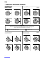
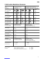
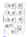
F 400 Castine Woodstove Clearances
Unprotected Surface
Parallel to the Wall Protected Surface
Parallel to the Wall
Unprotected Surface
Corner Installation Protected Surface
Corner Installation
E
F
G
H
CF
A
K
L
M
N
O
P
Q
R
B
I
IL
OR
S
T
U
V
W
X
U
X
D
PER NFPA 211 or
CAN/CSA-B365
PER NFPA 211 or
CAN/CSA-B365
Important:
Connector heatshields and double wall pipe must be a listed product.
Always follow the manufacturer’s instructions.
= SINGLE WALL PIPE WITH CONNECTOR SHIELDS = DOUBLE WALL PIPE
J
C
USA

13
Stove Unprotected Surface Protected Surface Installation
Clearances Installation PER NFPA211 OR CAN/CSA -B365-M93
SIDE REAR CORNER* SIDE REAR CORNER*
Stove -no heatshield 19" AA
AA
A 25" BB
BB
B 18" CC
CC
C 11” DD
DD
D 7" EE
EE
E 8" FF
FF
F
single wall pipe 485mm 635mm 460mm 280mm 180mm 205mm
Stove -with rear heatshield 18" GG
GG
G 18" HH
HH
H 13" II
II
I 11” JJ
JJ
J 7” KK
KK
K 8" LL
LL
L
single wall pipe 460mm 460mm 330mm 280mm 180mm 205mm
Stove -no heatshields 16” 19” 13” 8” 7” 6”
double wall pipe 405mm 485mm 330mm 205mm 180mm 150mm
Stove -with rear heatshield 15" M 7" NN
NN
N 11" OO
OO
O 8" PP
PP
P 7" QQ
QQ
Q 6" RR
RR
R
with connector shield 380mm 180mm 280mm 205mm 180mm 150mm
Stove -rear heatshield 15" SS
SS
S 7" TT
TT
T 11" UU
UU
U 8" VV
VV
V 7" WW
WW
W 6" XX
XX
X
with double wall pipe 380mm 180mm 280mm 205mm 180mm 150mm
Connector Unprotected Surface Protected Surface
Clearances (Pipe) Vertical Installation Vertical Inatallation
per NFPA211 OR CAN/CSA-B365-M93
Single wall pipe 25" 12"
635mm 300mm
Single wall pipe 18” 7”
with rear heatshield 460mm 180mm
Single wall pipe 7" 7"
with connector shields 180mm 180mm
Double wall pipe 7" 7"
180mm 180mm
Connector Unprotected Surface Protected Surface
Clearances (Pipe) Horizontal Installation Horizontal Installation
per NFPA211 OR CAN/CSA-B365-M93
Single wall connector 18" 460mm 7" 180mm
Double wall Pipe 6" 150mm 6" 150mm
Mantel and Trim Stove to 1" thick or less, side trim 13" 300mm
Clearances Stove to 1" thick or less, top trim 23" 585mm
Stove to mantel- maximum mantel depth 12" 25" 635mm
F 400 Castine Woodstove Clearances
USA


18
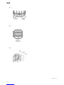
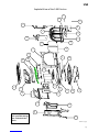
Parts list for the F 400
Castine woodstove
Consult your dealer for part numbers and
replacement parts.
1 Ashlip
2 Left door
3 Right door
4 Right side panel
5 Front panel
6 Top casting
7 Upper back panel
8 Smoke outlet
9 Back panel
10 Left side panel
11 Leg (long leg)
12 Upper bottom panel
13 Front door shaft (exterior)
Latch
Nut
Spring
14 Right burn plate
15 Right glass panel
16 Left glass panel
17 Air wash manifold
18 Top baffle (stainless steel)
19 Baffle cover (cast iron)
20 Air inspection cover
21 Rear burn plate
22 Fire brick (3)
23 Bottom grate
24 Left burn plate
25 Lower bottom panel
26 Ashpan housing
* Ashpan
27 Air slider/valve
28 Air devider
29 Door pins
30 Air control lever (chrome)
Allen head screw
31 Ashpan door
* Ashpan door pin
32 Ash door handle
Loop handle
Set screw
Latch
Spring
Nut
* Not shown
Appendix A
Alternate floor protection
All floor protection materials must be non-combustible ie. metal, brick,
stone, mineral fiber boards). Any combustible material may not be
used.
The easiest means of determining if a proposed alternate floor material
meets requirements listed in this manual is to follow this procedure.
R-value = thermal resistance
k-value = thermal conductivity
C-value = thermal conductance
1. Convert the specification to R-value;
a. If R-value is given, no conversion is needed.
b. If k-value is given with a required thickness (T) in inches: R=1/k X T.
c. If C-value is given: R=1/C.
2. Determine the R-value of the proposed alternate floor protector.
a. Use the formula in Step 1 to convert values not expressed as “R”.
b. For multiple layers, add R-values of each layer to determine overall
R-value.
3. If the overall R-value of the sustem is greater than the R-value of the
specified floor protector, the alternate is acceptable.
EXAMPLE:
The specified floor protector should be 3/4” thick material with a k-factor
of 0.84. The proposed alternate is 4” brick with a C-factor of 1.25 over 1/
8” mineral board witha k-factor of 0.29.
Step A. Use formula above to convert specifications to R-value. R=1/k X
T= 1/.84 X .75 = .893
Step B. Calculate R of proposed system.
4” brick of C-1.25, therefore R brick = 1/C = 1/1.25 = 0.80.
1/8” mineral board of k = 0.29 therefore
R mineral board = 1/.29 X 0.125 = 0.431
Total R = R brick + R mineral board=
0.8 + 0.431=1.231
Step C. Compare proposed system R = 1.231 to specified R of 0.893. Since
R is greater than required, the system is acceptable.
Definitions:
Thermal conductance =
C = Btu = W
(hr)(ft2)(F) (m2)(K)
Thermal conductivity =
k = Btu = W = (Btu)
(hr)(ft2)(F) (m2)(K) (hr)(ft)(F)
Thermal resistance=
R = Btu = (m2)(K) = (Btu)(inch)
(hr)(ft2)(F) W (hr)(ft2)(F)
THE JØTUL F 400 CASTINE WOODSTOVE REQUIRES FLOOR PROTECTION
WITH A MINIMUM INSULATING R VALUE OF 0.5.
ALCOVE INSTALLATION REQUIRE A MINIMUM R VALUE OF 1.6. (IF A UL/
ULC or WHI LISTED HEARTH PAD IS NOT USED.)
USA


La pagina si sta caricando...
La pagina si sta caricando...
La pagina si sta caricando...
La pagina si sta caricando...
La pagina si sta caricando...
La pagina si sta caricando...
La pagina si sta caricando...
La pagina si sta caricando...
La pagina si sta caricando...
La pagina si sta caricando...
La pagina si sta caricando...
La pagina si sta caricando...
La pagina si sta caricando...
La pagina si sta caricando...
La pagina si sta caricando...
La pagina si sta caricando...
La pagina si sta caricando...
La pagina si sta caricando...
La pagina si sta caricando...
La pagina si sta caricando...
La pagina si sta caricando...
La pagina si sta caricando...
La pagina si sta caricando...
La pagina si sta caricando...
La pagina si sta caricando...
La pagina si sta caricando...
La pagina si sta caricando...
La pagina si sta caricando...
La pagina si sta caricando...
La pagina si sta caricando...
La pagina si sta caricando...
La pagina si sta caricando...
La pagina si sta caricando...
La pagina si sta caricando...
La pagina si sta caricando...
La pagina si sta caricando...
La pagina si sta caricando...
La pagina si sta caricando...
La pagina si sta caricando...
La pagina si sta caricando...
-
 1
1
-
 2
2
-
 3
3
-
 4
4
-
 5
5
-
 6
6
-
 7
7
-
 8
8
-
 9
9
-
 10
10
-
 11
11
-
 12
12
-
 13
13
-
 14
14
-
 15
15
-
 16
16
-
 17
17
-
 18
18
-
 19
19
-
 20
20
-
 21
21
-
 22
22
-
 23
23
-
 24
24
-
 25
25
-
 26
26
-
 27
27
-
 28
28
-
 29
29
-
 30
30
-
 31
31
-
 32
32
-
 33
33
-
 34
34
-
 35
35
-
 36
36
-
 37
37
-
 38
38
-
 39
39
-
 40
40
-
 41
41
-
 42
42
-
 43
43
-
 44
44
-
 45
45
-
 46
46
-
 47
47
-
 48
48
-
 49
49
-
 50
50
-
 51
51
-
 52
52
-
 53
53
-
 54
54
-
 55
55
-
 56
56
-
 57
57
-
 58
58
-
 59
59
-
 60
60


Jøtul F 400 Installation And Operating Instructions Manual
- Categoria
- Stufe
- Tipo
- Installation And Operating Instructions Manual
in altre lingue
- English: Jøtul F 400
- français: Jøtul F 400
- español: Jøtul F 400
- Nederlands: Jøtul F 400
- dansk: Jøtul F 400
Documenti correlati
-
Jøtul Oslo F 500 Installation And Operating Instructions Manual
-
-
-
-
-
-
-
-
-
Altri documenti
-
Jotul F 600 Manuale del proprietario
-
-
Panadero E-40 Faro EcoDesign Istruzioni per l'uso
-
Panadero LUGANO Manuale utente
-
Panadero Inca Wall Manuale utente
-
Panadero Canada Eco Manuale utente
-
Panadero JAVA WALL Istruzioni per l'uso
-
United States Stove VG5722-W Manuale del proprietario
-
United States Stove Company US5522-W Manuale del proprietario
-
 Panadero OVAL 3S Manuale del proprietario
