HK Audio Linear 5 Manuale utente
- Categoria
- Altoparlanti della soundbar
- Tipo
- Manuale utente

Manual 1.0
• English
• Deutsch
• Français
• Italiano
• Español

Version 2.2 01/2011
Important Safety Instructions! Read before
connecting!
This product has been built by the manufacturer in accordance
with IEC 60065 and left the factory in safe working order. To
maintain this condition and ensure non-risk operation, the user
must follow the advice and warning comments found in the
operating instructions. If this product shall be used in vehicles,
ships or aircraft or at altitudes exceeding 2000 m above sea
level, take care of the relevant safety regulations which may
exceed the IEC 60065 requirements.
WARNING: To prevent the risk of fire and shock hazard, do not
expose this appliance to moisture or rain. Do not open case – no
user serviceable parts inside. Refer service to qualified service
personnel.
This symbol, wherever it appears, alerts you to the
presence of uninsulated dangerous voltage inside the enclosure –
voltage that may be sufficient to constitute a risk of shock.
This symbol, wherever it appears, alerts you to the
presence of externally accessible hazardous voltage. External
wiring connected to any terminal marked with this symbol must
be a “ready made cable” complying with the manufacturers
recommendations, or must be a wiring installed by instructed
persons only.
This symbol, wherever it appears, alerts you to important
operating and maintenance instructions in the accompanying
literature. Read the manual.
This symbol, wherever it appears, tells you: Take care!
Hot surface! To prevent burns you must not touch.
• Read these instructions.
• Keep these instructions.
• Follow all warnings and instructions marked on the product and
in this manual.
• Do not use this product near water. Do not place the product
near water, baths, wash basins, kitchen sinks, wet areas,
swimming pools or damp rooms.
• Do not place objects containing liquid on the product – vases,
glasses, bottles etc.
• Clean only with dry cloth.
• Do not remove any covers or sections of the housing.
• The set operating voltage of the product must match the local
mains supply voltage. If you are not sure of the type of power
available consult your dealer or local power company.
• To reduce the risk of electrical shock, the grounding of this
product must be maintained. Use only the power supply cord
provided with this product, and maintain the function of the
center (grounding) pin of the mains connection at any time. Do
not defeat the safety purpose of the polarized or grounding-
type plug.
• Protect the power cord from being walked on or pinched
particularly at plugs, convenience receptacles, and the point
where they exit from the device! Power supply cords should
always be handled carefully. Periodically check cords for cuts
or sign of stress, especially at the plug and the point where the
cord exits the device.
• Never use a damaged power cord.
• Unplug this product during lightning storms or when unused for
long periods of time.
• This product can be fully disconnected from mains only by
pulling the mains plug at the unit or the wall socket. The
product must be placed in such a way at any time, that
disconnecting from mains is easily possible.
• Fuses: Replace with IEC127 (5x20mm) type and rated fuse for
best performance only! It is prohibited to use “patched fuses”
or to short the fuse-holder. Replacing any kind of fuses must
only be carried out by qualified service personal.
• Refer all servicing to qualified service personnel. Servicing is
required when the unit has been damaged in any way, such as:
- When the power cord or plug is damaged or frayed.
- If liquid has been spilled or objects have fallen into the product.
- If the product has been exposed to rain or moisture.
- If the product does not operate normally when the operating
instructions are followed.
- If the product has been dropped or the cabinet has been
damaged.
• Do not connect external speakers to this product with an
impedance lower than the rated impedance given on the
product or in this manual. Use only cables with sufficient cross
section according to the local safety regulations.
• Keep away from direct sunlight.
• Do not install near heat sources such as radiators, heat
registers, stoves or other devices that produce heat.
• Do not block any ventilation openings. Install in accordance
with manufacturer’s instructions. This product must not be
placed in a built-in installation such as a rack unless proper
ventilation is provided.
• Always allow a cold device to warm up to ambient temperature,
when being moved into a room. Condensation can form inside it
and damage the product, when being used without warming up.
• Do not place naked flame sources, such as lighted candles on
the product.
• The device must be positioned at least 20 cm/8“ away from
walls.
• Use only with the cart, stand, tripod, bracket or table specified
by the manufacturer or sold with the product. When a cart is
used, use caution when moving the cart/product combination to
avoid injury from tip-over.
• Use only accessories recommended by the manufacturer, this
applies for all kind of accessories, for example protective
covers, transport bags, stands, wall or ceiling mounting
equipment. In case of attaching any kind of accessories to the
product, always follow the instructions for use, provided by the
manufacturer. Never use fixing points on the product other than
specified by the manufacturer.
• This appliance is NOT suitable to be used by any person or
persons (including children) with limited physical, sensorical or
mental ability, or by persons with insufficient experience and/
or knowledge to operate such an appliance. Children under
4 years of age must be kept away from this appliance at all
times.
• Never push objects of any kind into this product through
cabinet slots as they may touch dangerous voltage points or
short out parts that could result in risk of fire or electric shock.
• This product is capable of delivering sound pressure levels
in excess of 90 dB, which may cause permanent hearing
damage! Exposure to extremely high noise levels may cause a
permanent hearing loss. Wear hearing protection if continously
exposed to such high levels.
• The manufacturer only guarantees the safety, reliability and
efficiency of this product if:
- Assembly, extension, re-adjustment, modifications or repairs
are carried out by the manufacturer or by persons authorized
to do so.
- The electrical installation of the relevant area complies with the
requirements of IEC (ANSI) specifications.
- The unit is used in accordance with the operating instructions.
- The unit is regularly checked and tested for electrical safety by
a competent technician.
General Notes on Safety for Loudspeaker
Systems
Mounting systems may only be used for those loudspeaker
systems authorized by the manufacturer and only with the
mounting accessories specified by the manufacturer in the
installation instructions. Read and heed the manufacturer’s
installation instructions. The indicated load-bearing capacity
cannot be guaranteed and the manufacturer will not be liable for
damages in the event of improper installation or the use of
unauthorized mounting accessories.
The system’s load-bearing capacity cannot be guaranteed and
the manufacturer will not be liable for damages in the event
that loudspeakers, mounting accessories, and connecting and
attaching components are modified in any way.
Components affecting safety may only be repaired by the
manufacturer or authorized agents, otherwise the operating
permit will be voided.
Installation may be performed qualified personnel only, and
then only at pick-points with sufficient load-carrying capacity and
in compliance with local building regulations. Use only the
mounting hardware specified by the manufacturer in the
installation instructions (screws, anchors, etc.). Take all the
precautions necessary to ensure bolted connections and other
threaded locking devices will not loosen.
Fixed and portable installations (in this case, speakers and
mounting accessories) must be secured by two independent
safeties to prevent them from falling. Safeties must be able to
catch accessories or parts that are loose or may become loose.
Ensure compliance with the given national regulations when
using connecting, attaching, and rigging devices. Factor potential
dynamic forces (jerk) into the equation when determining the
proper size and load-bearing capacity of safeties.
Be sure to observe speaker stands’ maximum load-bearing
capacity. Note that for reasons of design and construction, most
speaker stands are approved to bear centric loads only; that is,
the speakers’ mass has to be precisely centered and balanced.
Ensure speaker stands are set up stably and securely. Take
appropriate added measures to secure speaker stands, for
example when:
- the floor or ground surface does not provide a stable, secure
base.
- they are extended to heights that impede stability.
- high wind pressure may be expected.
- there is the risk that they may be knocked over by people.
Special measures may become necessary as precautions against
unsafe audience behavior. Do not set up speaker stands in
evacuation routes and emergency exits. Ensure corridors are
wide enough and put proper barriers and markings in place
when setting speaker stands up in passageways. Mounting and
dismounting are especially hazardous tasks. Use aids suitable
for this purpose. Observe the given national regulations when
doing so.
Wear proper protection (in particular, a helmet, gloves, and
safety shoes) and use only suitable means of ascent (ladders,
scaffolds, etc.) during installation. Compliance with this
requirement is the sole responsibility of the company performing
the installation.
After installation, inspect the system comprised of the
mounting fixtures and loudspeakers to ensure it is properly
secured.
The operator of loudspeaker systems (fixed or portable) must
regularly inspect or task a third party to regularly inspect all
system components in accordance with the given country’s
regulations and have possible defects repaired immediately.
We also strongly recommend maintaining a logbook or the like to
document all inspections.
When deploying speakers outdoors, be sure to take into account
the stability and load-bearing capacity of platforms and surfaces;
loads and forces exerted by wind, snow, and ice; as well as
thermal influences. Also be sure to provide sufficient safety
margins for the rigging points used for flown systems. Observe
the given national regulations when doing so.
Professional loudspeaker systems can produce harmful
volume levels. Even prolonged exposure to seemingly harmless
levels (starting at about 95 dBA SPL) can cause permanent
hearing damage! Therefore we recommend that everyone who is
exposed to high volume levels produced by loudspeaker systems
wears professional hearing protection (earplugs or earmuffs).
Manufacturer: Stamer Musikanlagen GmbH, Magdeburger Str. 8,
66606 St. Wendel, Germany

Linear 5 1.0
3
Welcome to the HK Audio family!
Congratulations and thank you for choosing an HK AUDIO product.
LINEAR 5 is a line of active and passive loudspeaker cabinets that may be
combined in various ways to provide effective sound reinforcement.
You can use them individually as stand-alone units or in systems for delay
lines and zone coverage. All components are tuned and matched to deliver
excellent performance in every combination.
Two passive and two active subwoofers are available to extend and optimize
low-frequency response. You can mix and match these with the three
mid/ high units in half-stacks and full stacks to set up the right PA for the
situation. Linear 5 is a superb fullrange audio solution for top-40 cover
bands, open-air concerts in cities, club gigs, DJ events, beer tents, road-
shows, and mobile discos.
You’ll find detailed information, technical specifications, example applications
and lots of other helpful tips in this operating manual.
• English • Deutsch • Français • Italiano • Español

Linear 5 1.0
4
1 L5 112 XA / L5 112 FA / L5 115 FA
1.1 Control Features
Made in Germany
Leave enough space for proper ventilation!
+6 dB
0 dB
+6 dB
0 dB
Gain B
Mix Out
Thru B
Gain A
Thru A
Input BInput A
Small Venue
High Power
EQ
+4 dBu
L5 System
Gain
Green = On
Red = Limit/Error
Power
Line
Mic
On
Off
Caution:
To reduce
the risk of
electric shock,
grounding of
the center pin
of this plug
must be
maintained.
Caution: Risk of electric shock!
Do not open! Refer servicing to
qualified service personnel.
Serial No.
Mains
220-240 V~
50-60 Hz
3 A rated
current
2
3
1
4
5
6
10
9
7
8
1 Gain A/B
This knob adjusts the level of Input A / B.
2 Mic/Line (Input A only)
If you wish to connect a microphone, set the Line/Mic button to Mic.
This boosts Input A‘s sensitivity by 30 dB to optimize its gain structure
for mic signals.
3 Input A/B
These electronically balanced, combination XLR/ 6.3 mm (1/4") ports
accept audio signals.
4 Through A/B
This parallel output routes Input A/B’s incoming signal back out.
5 Gain
This switch adapts the inputs’ gain levels to match the signal source.
You have two options, +4 dBu and L5 System. Select L5 System and
set the Gain A and B knobs to the 12 o’clock position (0 dB/ center-
notched) to get a perfect match with other LINEAR series components.
6 EQ
• L5 112 FA / L5 115 FA
Small Venue
High Power
EQ
6
The switchable EQ (High Power/Small Venue) lets you voice this unit
for different applications. The High Power filter setting voices it for
applications demanding maximum performance, range and SPL.
Designed for smaller to midsized rooms, the Small Room EQ setting
lends the cab great depth and transparency to rival that of big studio
monitors.
• L5 112 XA
Monitor
Flat/Top
EQ
6
This switch optimizes the frequency response of the active L5 112 XA
for use as a mid/ high unit or as a monitor (placed on its side). Flat/Top
is the linear setting for use as a mid/ high unit with an added subwoofer
or as a standalone speaker. When the switch is set to Monitor, the high-
frequency driver’s dampening factor is reduced to ensure the speaker
cuts through on loud stages.
7 Status LED
This dual-color LED serves as a status indicator for the LINEAR 5 active
speaker (green = power on, red =limit/error). The LED briefly flashes red
to tell you the limiter is responding to signal peaks.
Caution! If the Status LED stays red during operation, it is being
overloaded. Turn down the signal level! If you are not routing a signal
in and the Status LED stays red, the system has detected a fault.
8 Power
This is the on/off button for the LINEAR 5 active speaker. Its status LED
lights up green when it is engaged.
Caution! A LINEAR 5 active speaker is automatically on standby as
soon as its cord is connected to a mains outlet. These speakers
consume about 0.25 watts per hour in standby mode.
9 Mains Input
Use the factory-included mains cord to connect this socket to a wall
outlet.
Note: All LINEAR 5 active speakers are equipped with V-Lock mains
sockets. If you use a VOLEX locking mains cord or another optionally
available brand with the same design, you can fix the mains cord in
place to prevent accidental disconnection.
10 Mix Out
This balanced XLR output routes Inputs A/B’s composite signal out. Use
the Gain A knob and the Mic/Line switch to adjust Input A’s signal level
and the Gain B knob to adjust Input B’s signal level.

Linear 5 1.0
5
1.2 Connecting Cords
Use a microphone cord equipped with XLR connectors or 6.3 mm (1/4")
jack plugs to send the signal from the audio source (monitor, line, or
a similar output) to the balanced A/B Inputs. If you wish to connect
a microphone directly without going into a mixer first, plug it into the
balanced Input A. Use a balanced XLR/ 6.3 mm (1/4”) microphone cord
to do this.
1.3 Operating the Speaker
• Ensure the LINEAR 5 active speaker’s Power button is set to off.
Caution! Always make sure the local mains voltage matches the
voltage specified on the LINEAR 5 active speaker. You may destroy
its electronic components if you connect it to the wrong mains
voltage.
• Turn the two Gain A and B knobs all the way down, rotating them
counterclockwise as far as they will go.
• Ensure all connected line sources are switched on before powering up.
First, switch on the connected mixer and all signal sources connected
to it, for example, keyboards, amps, effects, and so forth. Now make
sure the LINEAR 5 active speaker‘s Mic/Line switch is set correctly
(standard = Line). Always switch the LINEAR 5 active speaker on last,
that is, after you switch on all connected devices, and always switch it
off first, that is, before you switch off all connected devices.
• When you press the Power button, the fan will briefly start up (system
check) and stop after about five seconds. The fan is temperature-
controlled. It kicks on only at very high volume levels and runs
according to the given temperature. The Status LED lights up red
during the system check. It will light up green if there is no error and
the system is getting mains power.
• Turn the Gain knobs to the 12 o’clock position (0 dB /center-notched).
This is the preferred setting if you are using a mixing console to
address the LINEAR 5 active speaker. If you connect a CD player or
a keyboard directly, twist the Gain knob clockwise. Depending on the
input signal level, you may want to turn it all the way to the far right to
achieve maximum volume.
1.4 Settings
• Adjusting Volume Levels with the Gain Knobs
Turn these knobs and press the Mic/Line button (Input A only) to adjust
the level of incoming line and microphone signals. If you hear distortion
or the signal sounds saturated, first check the signal sources and, if
possible, reduce the output signal level there.
1.5 Alignment
Using the HK Audio DuoTilt ™ 3/7 on the L5 112 FA/
L5115 FA /L5112XA
The HK Audio DuoTiltTM 3/7 aligns LINEAR 5 active speakers
horizontally to prevent or minimize troublesome ceiling reflections. The
front opening of the HK Audio DuoTiltTM inclines the cabinet 3°, and the
rear opening 7°.
Without DuoTilt™ (top) and with DuoTilt™.
Select the 7° option when setting LINEAR 5 active speakers on fully
extended tripods or mounting poles. This angle gets the job done when
you want to address fewer listeners standing very near the speakers. If
you want to address an audience where more listeners are further away
from the speakers, opt for the 3° angle on the DuoTilt™.
1.6 Technical Specifi cations
See the chart on page 9.
• English • Deutsch • Français • Italiano • Español

Linear 5 1.0
6
2 L SUB 1200 A / L SUB 2000 A
2.1 Control Features
1 Gain Bass
This knob adjusts the subwoofer’s volume. When set to the 12 o’clock
position (0 dB /center-notched), the subwoofer’s volume is matched to
the LINEAR active speakers’ levels to achieve a balanced soundscape
with an evenhanded distribution of low and midrange frequencies. If you
want to increase or decrease the subwoofer’s volume, simply rotate the
knob to the left or right (control range +/-6 dB).
2 Power LED
This LED lights up green when the Power button is set to On and mains
power is provided
3 Limit LED
This LED lights up red when the power amp’s input signal is too high
or a fault has been detected. The LED briefly flashes red to tell you the
limiter is responding to signal peaks.
Caution! If the Limit LED stays red while the unit is up and running,
it is being overloaded. Turn down the signal level! If you are not
routing a signal in and the Limit LED stays red, the system has
detected a fault.
4 Confi guration
This switch optimizes the LINEAR active sub for deployment with other
LINEAR series units.
Set the switch to this position to configure the LINEAR active sub
for use with a LINEAR active speaker.
Set the switch to this position to operate two LINEAR active sub
with one LINEAR active speaker. In this setting, the levels of the two
Line Out Mid/High outputs are boosted by up to 6 dB to bring up the
one mid/ high unit’s level and balance it out with two LINEAR active
subs.
5 X-Over Bass
The X-Over switch lets you adjust the upper corner frequency of the
x-over built into the LINEAR active sub.
• L SUB 1200 A between 110 Hz and 130 Hz
• L SUB 2000 A between 100 Hz and 120 Hz
Your choice of setting will depend on the conditions in the venue and the
type of audio signal.
6 Phase
The Phase switch configures the LINEAR active sub’s phase position to
match that of the connected mid/ high units (0°/180°). Set the switch to
0° when operating the bass bin with LINEAR 5 mid/ high units. You may
have to invert the phase 180° to operate it with other speakers.
7 Line Out Mid/High L/R
Use these two electronically balanced XLR outputs to connect active
mid/ high units.
8 Input L/R
This electronically balanced, combination XLR/ 6.3 mm (1/4") input
accepts audio signals.
9 Thru L/R
This parallel output routes Input L/R’s incoming signal back out.
Caution:
To reduce the risk
of electric shock,
grounding of the
center pin of this
plug must be
maintained.
130 Hz
LR
LR
LR
Line Out
Mid/High
Input
Thru
Speaker Out
to L Sub 1200
Power Limit
110 Hz
180°
0°
Configuration X-Over Bass Phase
Leave enough space for proper ventilation!
Made in Germany
+6 dB–6 dB
Gain Bass
Mains Power
Leave enough space
for proper ventilation!
linear sub
2
1
21
Caution:
To reduce the risk
of electric shock,
grounding of the
center pin of this
plug must be
maintained.
Caution: Risk of electric shock!
Do not open! Refer servicing to
qualified service personnel.
120 Hz
LR
LR
LR
Line Out
Mid/High
Input
Thru
Power
Power Limit
100 Hz
180°
0°
Configuration X-Over Bass
Phase
Leave enough space for proper ventilation!
Made in Germany
+6 dB–6 dB
0 dB
Gain Bass
Mains
Leave enough space
for proper ventilation!
Serial No.
linear sub
220-240 V~ 50-60 Hz
3 A rated current
220-240 V~
50-60 Hz
3,3 A rated current
1
1
2 3
4 5 6
7
8
9
2 3
4 5 6
7
8
9
10
10
11
11
12

Linear 5 1.0
7
10 Power
This is the on/off button for the LINEAR 5 active sub. Its status LED
lights up green when it is engaged.
11 Mains
Use the factory-included mains cord to connect this socket to a wall
outlet.
Note: All LINEAR 5 active subs are equipped with V-Lock mains
sockets. If you use a VOLEX locking mains cord or another optionally
available brand with the same design, you can fix the mains cord in
place to prevent accidental disconnection.
12 Speaker Out (L SUB 1200 A only)
This port serves to connect a passive L SUB 1200.
Heads up: Do not connect any other device. If you do, it may be
destroyed along with L SUB 1200 A.
2.2 Connecting Cords
Use a microphone cord equipped with XLR connectors or 6.3 mm (1/4”)
jack plugs to send the signal from the audio source (master, monitor,
line, or a similar output) to the balanced L/R Inputs. Connect the active
mid/ high units to the XLR outputs labeled Line Out Mid/High. Use the
two Thru L/R ports to route the fullrange signal to other speakers.
2.3 Operating the Sub
• Ensure the LINEAR 5 active sub’s Power switch is set to off.
Caution! Always make sure the local mains voltage matches the
voltage specified on the LINEAR 5 active subwoofer. You may destroy
its electronic components if you connect it to the wrong mains
voltage.
• Turn the Gain Bass knob to the 12 o’clock position (0 dB/ center-
notched).
• Set the Configuration switch accordingly to match the number of
LINEAR active subs you are using.
• Ensure all connected line sources are switched on before powering up.
First, switch on the connected mixer and all signal sources connected
to it, for example, keyboards, amps, effects, and so forth. LINEAR
active speakers should always be connected to the Line Out Mid/High
ports and switched on after all other components are up and running.
When you’re ready to tear the rig down, please turn the LINEAR active
speaker down by rotating the Input A/B Gain knobs counterclockwise
as far as they will go and switch them off before powering down all
other connected devices.
• When you flip the Power switch, the fan will briefly start up (system
check) and stop after about five seconds. The fan is temperature-
controlled. It kicks on only at very high volume levels and runs
according to the given temperature. The Status LED lights up red
during the system check and will extinguish unless a fault is detected.
• The Power LED will light up green if the unit is getting mains voltage
after the Power switch has been engaged.
2.4 Settings
• Adjusting Volume Levels with the Gain Bass Knob
Use the Gain Bass knob to adjust the active subwoofer’s volume to
suit the venue and situation. If you want to increase or decrease the
subwoofer’s volume, simply turn this knob to the left or right (control
range +/-6 dB). If you hear distortion or the signal sounds saturated,
first check the signal sources and, if possible, reduce the output signal
level there.
• Adjusting the Corner Frequency with the X-Over Bass
Switch
You can use this switch to adjust the LINEAR active sub’s frequency
range to match the signal you wish to render and/or the surroundings.
The Line Out Mid/High Left/Right outputs are not affected by this
setting.
• Adjusting the Phase Position with the Phase Switch
You can use the Phase switch to adjust the LINEAR active sub’s phase
position to match that of the connected mid/ high unit. Always set this
switch to 0° when operating the bass bin with LINEAR 5 mid/ high
units. You may have to invert the phase to operate this sub with other
speakers. If so, set the switch to 180°.
2.5 Technical Specifi cations
See the chart on page 9.
3 Applications
See the appendix starting on page 42.
3 Application Samples
3.1 Mono Fullrange/Monitor System (L5 112 XA / L5 112 FA / L5 115 FA)
+6 dB
0 dB
+6 dB
0 dB
Gain B
Thru B
Gain A
Thru A
Input BInput A
Line
Mic
Mic
3.2 Stereo Fullrange System (L5 112 XA / L5 112 FA / L5 115 FA)
+6 dB
0 dB
+6 dB
0 dB
Gain B
Thru B
Gain A
Thru A
Input BInput A
Line
Mic
Line
+6 dB
0 dB
+6 dB
0 dB
Gain B
Thru B
Gain A
Thru A
Input BInput A
Line
Mic
Line
Left Right
• English • Deutsch • Français • Italiano • Español

Linear 5 1.0
8

Linear 5 1.0
9
Model L5 112 XA L5 112 FA L5 115 FA L Sub 1200 A L Sub 2000 A
Frequency response
+/– 3 dB
100 Hz – 18 kHz 64 Hz – 18 kHz 57 Hz – 18 kHz 55 Hz – X-Over 49 Hz – X-Over
Frequency response
–10 dB
72 Hz – 20 kHz 57 Hz – 20 kHz 48 Hz – 20 kHz 38 Hz – X-Over 39 Hz – X-Over
Axial sensitivity HF, 1W/1m 110 dB full-space ,
116 dB half-space
110 dB full-space,
116 dB half-space
110 dB full-space,
116 dB half-space
––
Axial sensitivity LF, 1W/1m 98 dB full-space,
104 dB half-space
98 dB full-space,
104 dB half-space
100 dB full-space,
106 dB half-space
95 dB full-space,
101 dB half-space
98 dB full-space,
104 dB half-space
Max. SPL@10% THD 129 dB half-space 127dB half-space 129 dB half-space 126 dB half-space 132 dB half-space
Max. SPL Peak@10% THD 135 dB half-space 134 dB half-space 139 dB half-space 128 dB half-space 133 dB half-space
Max. SPL Calc. 138 dB half-space 138 dB half-space 139 dB half-space 129 dB half-space 135 dB half-space
Amp/type Class D bi-amped Class D bi-amped Class D bi-amped Class D Class D
Power output 1,000 W 1,000 W 1,000 W 1,200 W 1,200 W
Amp to driver 350 W @ 4 Ohms 350 W @ 4 Ohms 350 W @ 4 Ohms – –
Amp to woofer 650 W @ 4 Ohms 650 W @ 4 Ohms 650 W @ 4 Ohms 1,200 W @ 4 Ohms 1,200 W @ 4 Ohms
Protective circuits, amp Under-voltage, thermal, short
circuit, and over-current
protection
Under-voltage, thermal, short
circuit, and over-current
protection
Under-voltage, thermal, short
circuit, and over-current
protection
Under-voltage, thermal, short
circuit, and over-current
protection
Under-voltage, thermal, short
circuit, and over-current
protection
Protective circuits,
speakers
Subsonic 24 dB/oct. peak limiter Subsonic 24 dB/oct. peak
limiter
Subsonic 24 dB/oct. peak
limiter
Subsonic 24 dB/oct. peak limiter Subsonic 24 dB/oct. peak limiter
Power consumption 3 A/230 V nominal pursuant to
EN600056
3 A/230 V nominal pursuant to
EN600056
3 A/230 V nominal pursuant to
EN600056
3.3 A/230 V nominal pursuant to
EN600056
3.3 A/230 V nominal pursuant to
EN600056
Input sensitivity +4 dBu @ Gain center-notched/
L5 System Level
+4 dBu @ Gain center-
notched/ L5 System Level
+4 dBu @ Gain center-notched/
L5 System Level
+4 dBu @ Gain Center click +4 dBu @ Gain center-notched
Audio ports 2x XLR In, 2x XLR-Thru,
1x XLR Mix Out
2x XLR In, 2x XLR-Thru,
1x XLR Mix Out
2x XLR In, 2x XLR-Thru,
1x XLR Mix Out
2x XLR In, 2x XLR-Thru, 2x XLR
Mid/High Out, Speakon NL4 for
2nd passive L Sub 1200
2x XLR In, 2x XLR-Thru,
2x XLR-Mid/High Out
Mains connector 1x IEC socket with V-Lock cord
retainer
1x IEC socket with V-Lock
cord retainer
1x IEC socket with V-Lock cord
retainer
1x IEC socket with V-Lock cord
retainer
1x IEC socket with V-Lock cord
retainer
Bass woofer 1x 12" with 2.5" voice coil
(4 Ohms)
1x 12" with 2.5" voice coil
(4 Ohms)
1x 15" with 3" voice coil
(4 Ohms)
2x 10" (4 Ohms) with 2.5" voice
coil featuring Advanced Cooling
technology
2x 12" (8 Ohms) with 2.5" voice
coil featuring Advanced Cooling-
technology
HF driver 1" with 1.75" voice coil
(16 Ohms)
1" with 1.75" voice coil
(16 Ohms)
1" with 1.75" voice coil
(16 Ohms)
––
Horn directivity 60° x 40° CD horn, rotatable 60°–90° (asy.) x 55° CD horn,
rotatable
60°–90° (asy.) x 55° CD horn,
rotatable
––
X-over frequency 1.65 kHz, 24 dB/oct. active 1.65 kHz, 24 dB/oct. active 1.65 kHz, 24 dB/oct. active 110/130 Hz variable with
24 dB/oct.
100/120 Hz variable with
24 dB/oct.
Pole mount DuoTilt™ 3/7 DuoTilt™ 3/7 DuoTilt™ 3/7 2x M20 M20
Rigging/ pick points 3x M8 3x M8 3x M8 - -
Grips 2, integrated 2, integrated 2, integrated 4, integrated 4, integrated
Optional accessories Protective cover Protective cover Protective cover Protective cover, mounting
hardware for casters, tilt unit
Protective cover, mounting
hardware for casters, tilt unit
Housing Hybrid (birch multiplex / MDF) Hybrid (birch multiplex / MDF) Hybrid (birch multiplex / MDF) Birch multiplex 15/18 mm,
9/13 ply
Birch multiplex 15/18 mm, 9/13
ply
Front grille 2 mm metal grille backed with
black acoustic foam
2 mm metal grille backed with
black acoustic foam
2 mm metal grille backed with
black acoustic foam
2 mm metal grille 2 mm metal grille
Finish Acrylic enamel, black Acrylic enamel, black Acrylic enamel, black Acrylic enamel, black Acrylic enamel, black
Dimensions (WxHxD) 37 x 66.8 x 30 cm 37 x 66.8 x 36.5 cm 44.9 x 70.8 x 45 cm 38 x 66.8 x 56 cm 50.6 x 80.6 x 61 cm
14-9/16 x 26-19/64 x 11-13/16" 14-9/16 x 26-19/64 x 14-3/8" 17-43/64 x 27-7/8 x 17-23/32" 14-31/32 x 26-19/64 x 22-3/64" 19-11/16 x 31-47/64 x 24-1/64"
Weight 21.1 kg / 46.5 lbs. 23.9 kg / 52.7 lbs. 30.7 kg / 67.7 lbs. 30.7 kg / 67.7 lbs. 46.2 kg / 101.9 lbs.
Technical Specifi cations
• English • Deutsch • Français • Italiano • Español

Version 2.2 01/2011
Wichtige Sicherheitshinweise! Bitte vor
Anschluss lesen!
Dieses Produkt wurde gemäß IEC 60065 hergestellt und hat
das Werk in einem sicheren, betriebsfähigen Zustand verlassen.
Um diesen Zustand zu erhalten und um einen gefahrlosen
Betrieb zu gewährleisten, ist es notwendig, dass der Benutzer
die Empfehlungen und Warnhinweise befolgt, die in der
Betriebsanleitung zu finden sind. Bei Einsatz dieses Produktes
in Fahrzeugen, Schiffen oder Flugzeugen, oder in Höhen
oberhalb 2000 m Meereshöhe müssen die entsprechenden
Sicherheitsstandards zusätzlich zur IEC 60065 beachtet werden.
WARNUNG: Um das Risiko von Feuer oder Stromschlag zu
verhüten, darf dieses Gerät nicht Feuchtigkeit oder Regen
ausgesetzt werden. Öffnen Sie das Gehäuse nicht – im Inneren
gibt es keine Bauteile, die vom Benutzer wartbar sind. Die
Wartung darf nur von einem qualifiziertem Kundendienst
durchgeführt werden.
Dieses Symbol, wo immer es erscheint, warnt Sie vor
gefährlicher, nicht isolierter Spannung im Gehäuse – Spannung,
die möglicherweise genügt, eine Stromschlaggefahr darzustellen.
Dieses Symbol, wo immer es erscheint, warnt Sie vor
außen zugänglicher, gefährlicher Spannung. Eine Verbindung zu
jeder Anschlussklemme, die mit diesem Symbol versehen ist, darf
nur mit konfektioniertem Kabel hergestellt werden, dass den
Empfehlungen des Herstellers genügt, oder mit Kabel, das von
qualifiziertem Personal installiert wurde.
Dieses Symbol, wo immer es erscheint, macht Sie auf
wichtige Bedienungs- und Wartungsanweisungen aufmerksam,
die in beiliegenden Unterlagen zu finden sind. Bitte lesen Sie das
Handbuch.
Dieses Symbol, wo immer es erscheint, sagt Ihnen:
Vorsicht! Heiße Oberfläche! Um Verbrennungen zu vermeiden,
nicht anfassen.
• Bitte lesen Sie diese Anweisungen.
• Bewahren Sie diese Anweisungen auf.
• Befolgen Sie alle Warnhinweise und Anweisungen auf dem
Gerät und in dieser Anleitung.
• Benutzen Sie dieses Gerät nicht in der Nähe von Wasser. Stellen
Sie das Gerät nicht in der Nähe von Wasser, Badewannen,
Waschbecken, Küchenspülen, nassen Stellen, Schwimmbecken
oder feuchten Räumen auf.
• Stellen Sie keine Gefäße, wie Vasen, Gläser, Flaschen usw., die
Flüssigkeiten enthalten, auf das Gerät.
• Reinigen Sie das Gerät nur mit einem trockenen Tuch.
• Entfernen Sie keine Abdeckungen oder Teile des Gehäuses.
• Die auf dem Gerät eingestellte Betriebsspannung muss mit der
örtlichen Spannung der Netzstromversorgung übereinstimmen.
Wenn Sie sich nicht sicher sind, welche Spannung in Ihrem
Netz zur Verfügung steht, konsultieren Sie bitte Ihren Händler
oder den örtlichen Stromversorger.
• Um das Risiko eines Stromschlags zu verringern, muss die
Erdung des Gerätes beibehalten werden. Verwenden Sie nur das
mitgelieferte Stromführungskabel und behalten Sie die Funktion
der seitlichen, geerdeten Schutzkontakte des Netzanschlusses
immer aufrecht. Versuchen Sie nicht, die Sicherheitsaufgabe
des geerdeten Steckers zu umgehen.
• Schützen Sie das Stromführungskabel vor Betreten
und Quetschen, besonders in der Nähe der Stecker,
Gerätesteckdosen – und dort, wo sie am Gerät austreten!
Stromführungskabel sollten immer vorsichtig behandelt werden.
Kontrollieren Sie die Stromführungskabel in regelmäßigen
Abständen auf Einschnitte und Anzeichen von Abnutzung,
besonders in der Nähe des Steckers und an der Verbindung
zum Gerät.
• Benutzen Sie niemals ein beschädigtes Stromführungskabel.
• Ziehen Sie bei Gewittern den Stecker des Gerätes und wenn
das Gerät über einen längeren Zeitraum nicht benutzt wird.
• Dieses Gerät wird nur vollständig von Stromnetz getrennt, wenn
der Stecker vom Gerät oder aus der Steckdose gezogen wird.
Das Gerät sollte so aufgestellt werden, dass das Trennen vom
Stromnetz leicht möglich ist.
• Sicherungen: Ersetzen Sie Sicherungen nur mit dem Typ IEC127
(5x20mm) und dem korrekten Nennwert, um die optimale
Leistung zu gewährleisten! Es ist untersagt, kurzgeschlossene
Sicherungen zu verwenden oder den Sicherungshalter zu
überbrücken. Sicherungen dürfen nur von qualifiziertem
Personal gewechselt werden.
• Alle Wartungsarbeiten sollten nur von qualifiziertem Personal
ausgeführt werden. Wartung ist notwendig, wenn das Gerät auf
irgendeine Weise beschädigt wurde, wie zum Beispiel:
- Wenn das Stromführungskabel oder der Stecker beschädigt
oder abgenutzt ist.
- Wenn Flüssigkeit oder Gegenstände in das Gerät gelangt sind.
- Wenn das Gerät Regen oder Feuchtigkeit ausgesetzt war.
- Wenn das Gerät nicht ordnungsgemäß funktioniert, obwohl die
Bedienungsanleitung beachtet wurde.
- Wenn das Gerät hingefallen ist oder das Gehäuse beschädigt
wurde.
• Beim Anschluss von Lautsprechern an dieses Gerät darf
die auf dem Gerät oder in dieser Anleitung angegebene
Mindestimpedanz nicht unterschritten werden. Die verwendeten
Kabel müssen entsprechend den lokalen Regelungen über einen
ausreichenden Querschnitt verfügen.
• Halten Sie das Gerät vom Sonnenlicht fern.
• Installieren Sie das Gerät nicht in der Nähe von Wärmequellen,
wie zum Beispiel Heizkörper, Heizregister, Öfen oder anderen
Geräten, die Hitze erzeugen.
• Verstopfen Sie nicht die Lüftungsöffnungen. Installieren Sie
das Gerät entsprechend der Anleitung des Herstellers. Das
Gerät darf nicht eingebaut werden – wie zum Beispiel in einen
Gestellrahmen, es sei denn, dass für angemessene Belüftung
gesorgt wird.
• Ein kaltes Gerät sollte immer auf die Umgebungstemperatur
erwärmt werden, wenn es in einen Raum transportiert wird.
Es könnte sich Kondensation im Inneren bilden, die das Gerät
beschädigt, wenn es ohne vorherige Erwärmung benutzt wird.
• Stellen Sie keine offenen Flammen, wie brennende Kerzen, auf
das Gerät.
• Das Gerät sollte mindestens 20 cm von Wänden aufgestellt
werden.
• Das Gerät darf nur mit Rollwagen, Ständern, Stativen,
Tischen oder Halterungen benutzt werden, die vom Hersteller
spezifiziert sind oder zusammen mit dem Gerät verkauft
wurden. Wenn ein Rollwagen benutzt wird, seien Sie vorsichtig,
wenn Sie die Rollwagen/Geräte-Kombination transportieren, um
Verletzungen durch Umkippen zu vermeiden.
• Verwenden Sie nur Zubehör, das vom Hersteller empfohlen
ist. Das gilt für alle Arten von Zubehör, wie zum Beispiel
Schutzabdeckungen, Transporttaschen, Ständer sowie Wand-
und Deckenhalterungen. Wenn Sie irgendein Zubehör am Gerät
anbringen, befolgen Sie immer die Anleitungen des Herstellers.
Benutzen Sie nur die Befestigungspunkte des Geräts, die vom
Hersteller vorgesehen sind.
• Dieses Gerät ist NICHT geeignet für eine Person oder Personen
(einschließlich Kindern) mit eingeschränkten physischen,
sensorischen und geistigen Fähigkeiten, oder für Personen mit
unzulänglicher Erfahrung und/oder Fachkenntnis, um solch
ein Gerät zu bedienen. Kinder unter 4 Jahren sollten stets von
diesem Gerät fern gehalten werden.
• Es sollten keinerlei Gegenstände durch die Gehäuseschlitze
eingeführt werden, da dadurch gefährliche, spannungsführende
Bauteile berührt oder kurzgeschlossen werden können. Dies
könnte zu einer Feuer- oder Stromschlaggefahr führen.
• Dieses Gerät ist imstande, Schalldruckpegel von mehr als
90 dB zu produzieren. Dies könnte zu einem dauerhaften
Hörschaden führen! Eine Belastung durch extrem hohe
Geräuschpegel kann zu einem dauerhaften Gehörverlust führen.
Bei einer anhaltenden Belastung durch solch hohe Pegel sollte
ein Gehörschutz getragen werden.
• Der Hersteller gewährleistet die Sicherheit, Zuverlässigkeit und
Leistung des Gerätes nur unter folgenden Voraussetzungen:
- Einbau, Erweiterung, Neueinstellung, Modifikationen oder
Reparaturen werden vom Hersteller oder autorisiertem Personal
ausgeführt.
- Die elektrische Installation des betreffenden Bereiches
entspricht den Anforderungen der IEC (ANSI) Maßgaben.
- Das Gerät wird entsprechend der Bedienungsanleitung benutzt.
- Das Gerät wird regelmäßig von einem fachkundigen Techniker
auf elektrische Sicherheit geprüft und getestet.
Allgemeine Sicherheitshinweise für
Lautsprechersysteme
Befestigungssysteme dürfen ausschließlich für die vom
Hersteller freigegebenen Lautsprechersysteme und mit dem in
der Montageanleitung genannten Montage-Zubehör verwendet
werden. Die Montagehinweise des Herstellers sind dabei
unbedingt zu beachten. Bei unsachgemäßer Montage bzw.
Verwendung von nicht freigegebenem Montage-Zubehör kann die
angegebene Belastung nicht garantiert und keinerlei Haftung
seitens des Herstellers übernommen werden.
Sollten Änderungen an Lautsprechern, an Montage-Zubehör,
Verbindungs- und Befestigungselementen sowie Anschlagmitteln
vorgenommen werden, kann die Tragfähigkeit des Systems nicht
mehr garantiert werden und seitens des Hersteller keinerlei
Haftung übernommen werden.
Reparaturen an sicherheitsrelevanten Bauteilen dürfen nur
vom Hersteller oder Bevollmächtigten durchgeführt werden,
andernfalls erlischt die Betriebserlaubnis.
Die Installation darf ausschließlich durch Sachkundige und
nur an Montagepunkten mit ausreichender Tragfähigkeit, ggf.
unter der Berücksichtigung von Bauauflagen, erfolgen. Das vom
Hersteller in der Montageanleitung vorgeschriebene
Befestigungsmaterial (Schrauben, Dübel, etc.) muss verwendet
werden. Schraubverbindungen müssen durch geeignete
Maßnahmen gegen Lösen gesichert sein.
Ortsfeste oder mobile Installationen (hier Lautsprecher inkl.
Montagezubehör) müssen durch zwei unabhängig voneinander
wirkende Einrichtungen gegen Herabfallen gesichert sein. Lose
Zusatzteile oder sich lösende Teile müssen durch geeignete
Einrichtungen aufgefangen werden können. Bei Verwendung von
Verbindungs- und Befestigungselementen sowie Anschlagmitteln
sind die nationalen Vorschriften zu beachten. Hinsichtlich der
Bemessung der Sicherungsmittel sind mögliche dynamische
Belastungen (Ruckkräfte) mit zu berücksichtigen.
Bei Stativen ist vor allem die maximale Traglast zu
beachten. Außerdem sind die meisten Stative aus konstruktiven
Gründen nur für das Tragen von genau zentrischer Belastung
zugelassen. Stative müssen standsicher aufgestellt werden.
Stative sind durch geeignete Maßnahmen zusätzlich zu sichern,
wenn zum Beispiel:
- ihre Aufstandfläche keinen sicheren Stand zulässt,
- ihre Höhen die Standsicherheit einschränken,
- mit zu hohem Winddruck zu rechnen ist,
- damit zu rechnen ist, dass sie durch Personen umgestoßen
werden.
Besondere Maßnahmen können auch zur Vorsorge gegen
gefährdendes Verhalten von Zuschauern erforderlich werden.
Stative dürfen nicht in Flucht- und Rettungswegen aufgestellt
werden. Bei Aufstellung in Verkehrswegen ist auf die erforderliche
Breite der Wege und auf ordnungsgemäße Absperrung sowie
Kennzeichnung zu achten. Beim Auf- und Absetzen ist eine
besondere Gefährdung gegeben. Hierzu sind geeignete Hilfsmittel
zu verwenden. Es sind hierbei die nationalen Vorschriften zu
beachten.
Während der Montage ist geeignete Schutzausrüstung
(insbesondere Kopfschutz, Handschuhe und Sicherheitsschuhe) zu
tragen und es sind nur geeignete Aufstiegshilfen (Leitern,
Gerüste, etc.) zu verwenden. Die Verantwortung dafür liegt alleine
beim ausführenden Installationsbetrieb.
Nach der Montage ist die Aufhängung des System aus
Halterung und Lautsprecher auf sichere Befestigung zu
überprüfen.
Der Betreiber von Lautsprechersystemen (ortsfest oder mobil) ist
verpflichtet, alle Systemkomponenten unter Berücksichtigung der
jeweils nationalen Regelungen regelmäßig zu überprüfen bzw.
prüfen zu lassen und mögliche Schäden unverzüglich beseitigen
zu lassen.
Weiterhin raten wir dringend zu einer ausführlichen
Dokumentation aller Überprüfungsmaßnahmen
in Prüfbüchern o.ä.
Beim Einsatz von Lautsprechern im Freien sind für
Standsicherheit und Tragfähigkeit von Aufbauten und Flächen
insbesondere auch die Windlasten, Schnee- und Eislasten
sowie thermische Einflüsse zu berücksichtigen. Insbesondere
die Lastaufnahmepunkte geflogener Systeme sollten hier mit
ausreichenden Sicherheitsreserven dimensioniert werden. Es sind
hierbei die nationalen Vorschriften zu beachten.
Professionelle Lautsprechersysteme sind in der Lage,
gesundheitsschädliche Schallpegel zu erzeugen. Selbst die
Einwirkung scheinbar harmloser Schallpegel über einen längeren
Zeitraum kann zu bleibenden Schäden am Gehör führen (ab ca.
95 dBA SPL)! Daher raten wir für alle Personen, die durch den
Betrieb von Lautsprechersystemen dem Einfluss hoher
Schallpegel ausgesetzt sind, zum Tragen von professionellem
Gehörschutz (Ohrstöpsel oder Kapselgehörschutz).
Hersteller: Stamer Musikanlagen GmbH, Magdeburger Str. 8,
66606 St. Wendel, Deutschland

Linear 5 1.0
11
Willkommen in der HK Audio Familie!
Vielen Dank, dass Sie sich für ein HK AUDIO Produkt entschieden haben.
LINEAR 5 ist eine Serie von aktiven und passiven Lautsprechern, die auf
verschiedene Art und Weise zur effektiven Beschallung kombiniert werden
können. Sie können einzeln oder im System, als Zonenlautsprecher oder
Delay-System verwendet werden. Dabei sind alle Komponenten für die
unterschiedlichen Kombinationen optimal vorbereitet
Zur Erweiterung und Optimierung des unteren Frequenzbereichs stehen zwei
passive und zwei aktive Subwoofer zur Verfügung, die zusammen mit den
drei Topteilen zu idealen Half- und Fullstack Beschallungslösungen werden.
LINEAR 5 eignet sich im Besonderen für Anforderungen im Fullrange-
Audiobereich bei Top-40-Gigs, City-Open-Airs, Club-Gigs, DJ-Events,
Festzeltbeschallungen, Road-Shows oder mobilen Disco-Veranstaltungen.
Weitere hilfreiche Details, technische Daten und Anwendungsbeispiele
entnehmen Sie bitte der folgenden Bedienungsanleitung.
• English • Deutsch • Français • Italiano • Español

Linear 5 1.0
12
1 L5 112 XA / L5 112 FA / L5 115 FA
1.1 Bedienelemente
Made in Germany
Leave enough space for proper ventilation!
+6 dB
0 dB
+6 dB
0 dB
Gain B
Mix Out
Thru B
Gain A
Thru A
Input BInput A
Small Venue
High Power
EQ
+4 dBu
L5 System
Gain
Green = On
Red = Limit/Error
Power
Line
Mic
On
Off
Caution:
To reduce
the risk of
electric shock,
grounding of
the center pin
of this plug
must be
maintained.
Caution: Risk of electric shock!
Do not open! Refer servicing to
qualified service personnel.
Serial No.
Mains
220-240 V~
50-60 Hz
3 A rated
current
2
3
1
4
5
6
10
9
7
8
1 Gain A/B
Mit diesem Regler wird der Eingangspegel des Input A / B angepasst.
2 Mic/Line Schalter (nur Input A)
Wenn Sie ein Mikrofon anschließen, stellen Sie mit Hilfe des Line/
Mic-Schalters die Empfindlichkeit auf „Mic“. Dadurch wird die
Eingangsempfindlichkeit des Input A um 30 dB erhöht und der Eingang
für Mikrofonsignale optimiert.
3 Input A/B
Elektronisch symmetrierte, kombinierte XLR/Klinken-Eingangsbuchse für
das Musiksignal.
4 Through A/B
Paralleler Ausgang zur Weiterleitung der Eingangssignale von Input A/B.
5 Gain-Schalter
Mit diesem Schalter kann eine Anpassung der Eingangsempfindlich-
keiten der Inputs an die Signalquelle vorgenommen werden. Es stehen
zwei Anpassungen zur Verfügung „+4 dBu“ bzw. „L5 System“. Die
Stellung „L5 System“ garantiert bei Mittelstellung der Gainregler A
und B (0 dB /Centerclick), ein perfektes Zusammenspiel mit anderen
Komponenten der LINEARSerie.
6 EQ
• L5 112 FA / L5 115 FA
Small Venue
High Power
EQ
6
Der umschaltbare EQ (High Power/Small Venue) wurde speziell
für unterschiedliche Anwendungen designed. Bei „High-Power“-
Anwendungen wird der Box größte Durchsetzungskraft und Reichweite
abverlangt, dieser Filter eignet sich also für alle Anwendungen, bei
denen maximaler Schalldruck gefordert ist. Beim Einsatz in kleineren bis
mittleren Räumen und Dynamik überzeugt die Box in der EQ-Einstellung
„Small Room“ durch besonders viel Tiefgang und mit einer Transparenz,
die an die Qualität großer Studiomonitore erinnert.
• L5 112 XA
Monitor
Flat/Top
EQ
6
Dieser Schalter optimiert den Frequenzgang des L5 112 XA Aktivlaut-
sprechers für den Einsatz als Topteil oder als Monitor (liegend): die
lineare Einstellung „Flat/Top“ für den Einsatz als Topteil mit einem
zusätzlichen Subwoofer bzw. für den Standalone-Betrieb – in der
Schalterstellung „Monitor“ wird der Hochtontreiber etwas unbedämpfter,
was zu einer hohen Durchsetzungsfähigkeit des Lautsprechers bei
Monitoranwendungen auf lauten Bühnen führt.
7 Status LED
Zweifarbige LED als Statusanzeige des LINEAR 5 Aktivlautsprechers
(Grün = Power On, Rot = Limit/Fehler). Ein kurzzeitiges Aufleuchten der
LED zeigt das Arbeiten des Limiters bei Pegelspitzen an.
Achtung! Leuchtet die Signal LED während dem Betrieb dauerhaft
rot, wird das System überlastet. Reduzieren Sie den Signalpegel!
Wenn kein Programmsignal anliegt und die Status LED dauerhaft rot
leuchtet, liegt ein Fehler vor.
8 Power-Schalter
Der Ein/Aus-Schalter für die LINEAR5 Aktivlautsprecher. In
eingeschaltetem Zustand leuchtet die Status LED grün.
Achtung! Sobald ein Stromkabel an die LINEAR5 Aktivlautsprecher
angeschlossen wird, befindet sich die Lautsprecher im
Standby modus. Im Standbymodus verbrauchen die LINEAR5
Aktivlautsprecher ca. 0,25 Watt/Stunde.
9 Mains Input
Verbinden Sie diese Anschlussbuchse mittels eines Kaltgeräte-
stromkabels (im Lieferumfang enthalten) mit der Netzsteckdose.
Hinweis: Alle LINEAR 5 Aktivlautsprecher sind mit verriegelbaren
V-Lock Netzeingangsbuchsen ausgestattet. In Kombination mit einem
verriegelbaren Anschlusskabel (VOLEX oder baugleich, optional
erhältlich) kann das Netzkabel arretiert werden und so gegen
versehentliches Herausrutschen gesichert werden.
10 Mix Out
Symmetrischer XLR-Ausgang zum Weiterschleifen des Summensignals
der Inputs A/B. Das Summensignal wird mit dem Gain-Regler A und
dem Mic/Line-Schalter für den Input A geregelt und mit dem Gain-
Regler B für den Imput B.

Linear 5 1.0
13
1.2 Anschlüsse und Verkabelung
Schließen Sie die von Ihrer Musikquelle kommenden Signalkabel
(Monitor Out, Line Out o.ä.) an die symmetrierten Input-Buchsen A/B mit
einem XLR/Klinken-Mikrofonkabel an. Falls Sie ein Mikrofon direkt ohne
Mischpult an den LINEAR5 Aktivlautsprecher anschließen möchten,
verwenden Sie den symmetrierten Input A und schalten Sie den Mic/
Line-Schalter auf Mic. Verwenden Sie auch hierzu ein symmetrisches
XLR/Klinken-Mikrofonkabel.
1.3 Inbetriebnahme
• Achten Sie darauf, dass der LINEAR5 Aktivlautsprecher
ausgeschaltetist.
Achtung! Achten Sie darauf, dass die Spannungsangabe des
LINEAR5 Aktivlautsprechers der Netzspannung entspricht. Der
Anschluss an eine falsche Netzspannung kann die elektronischen
Elemente des LINEAR5 Aktivlautsprechers zerstören.
• Drehen Sie die beiden Gain-Regler (Gain A/Gain B) ab (Anschlag links).
• Achten Sie beim Anschluss eines Line-Signals darauf, dass alle
übrigen angeschlossenen Komponenten schon vorher in Betrieb
sind. Sowohl das angeschlossene Mischpult als auch alle mit ihm
verbundenen Signalquellen wie Keyboards, Instrumentalverstärker,
Effekte usw. sollten eingeschaltet sein. Achten Sie nun darauf,
dass der Mic/Line-Schalter des LINEAR5 Aktivlautsprechers richtig
eingestellt ist (Standard = Line). Der LINEAR5 Aktivlautsprecher sollte
immer zuletzt, d.h. nach allen anderen Komponenten, eingeschaltet,
und zuerst, d.h. vor allen angeschlossenen Geräten, ausgeschaltet
werden.
• Nach dem Einschalten mit dem Power-Schalter läuft der Lüfter kurz
an (Systemcheck) und geht nach ca. 5 Sekunden aus. Der Lüfter ist
temperaturgesteuert. Er geht nur bei sehr hohen Lautstärken in Betrieb
und regelt sich temperaturabhängig. Während des Systemchecks
leuchtet die Status-LED rot – sie wird grün wenn kein Fehler vorliegt
und Netzspannung anliegt.
• Drehen Sie die Gain-Regler in die Mitte (0 dB /Centerclick). Wenn
Sie ein Mischpult zur Ansteuerung des LINEAR5 Aktivlautsprechers
benutzen, ist diese Pegelstellung zu bevorzugen. Falls Sie direkt
einen CD-Player oder z.B. ein Keyboard anschließen, kann je nach
Signalstärke der Gain-Regler ganz nach rechts gedreht werden, um
die maximale Lautstärke zu erzielen.
1.4 Einstellungen
• Lautstärkeanpassung mit den Gain-Reglern
Passen Sie mit diesen Reglern und durch Drücken des Mic/Line-
Schalters (nur Input A) das Eingangssignal für Line- und Mikrofonsignale
an. Falls Verzerrungen oder Übersteuerungen auftreten, überprüfen
Sie die Signalquellen und reduzieren Sie nach Möglichkeit dort das
Ausgangssignal.
1.5 Ausrichtung
HK Audio DuoTilt ™ 3/7 bei L5 112 FA/ L5 115 FA /
L5112XA
Mit dem HK Audio DuoTilt™ 3/7 können die LINEAR5 Aktivlautsprecher
horizontal ausgerichtet werden. Dadurch können störende Reflexionen
an der Decke vermieden bzw. verringert werden. Mit der vorderen Öff-
nung im DuoTilt beträgt der Neigungswinkel 3° und mit der hinteren 7°.
Ohne DuoTilt™ (oben) und mit DuoTilt™.
Wird ein LINEAR5 Aktivlautsprecher auf einem voll ausgefahrenem
Boxenstativ bzw. Distanzstange betrieben, sollte der 7°-Winkel benutzt
werden. Diese Einstellung eignet sich besonders gut, wenn weniger
Zuhörer beschallt werden sollen, die unmittelbar in der Nähe der
Lautsprecherboxen stehen. Sollen mehr Zuhörer beschallt werden,
die sich weiter weg von den Lautsprechern befinden, eignet sich der
3°-Winkel des DuoTilt™.
1.6 Technische Daten
siehe Seite 17
• English • Deutsch • Français • Italiano • Español

Linear 5 1.0
14
2 L SUB 1200 A / L SUB 2000 A
2.1 Bedienelemente
1 Gain Bass
Mit diesem Regler wird die Lautstärke des Subwoofers angepasst. In
Mittenstellung (0 dB /Centerclick) ist die Lautstärke des Subwoofers
an die LINEAR Aktivlautsprecher so angepasst, dass ein homogener
Klangeindruck mit ausgewogenem Bass und Mittelhochton-Anteil
besteht. Durch Drehen des Gain Bass-Reglers nach links oder rechts
kann die Lautstärke des Subwoofers bei Bedarf verringert bzw. erhöht
werden (Regelbereich+/–6dB).
2 Power LED
Diese LED leuchtet grün, wenn der Powerschalter auf „On“ geschaltet
ist und eine Stromverbindung besteht.
3 Limit LED
Diese LED leuchtet rot, wenn das Einganssignal der Endstufe zu hoch
Ist oder ein Fehler vorliegt. Ein kurzzeitiges Aufleuchten der LED zeigt
das Arbeiten des Limiters bei Pegelspitzen an.
Achtung! Leuchtet die Limt LED während dem Betrieb dauerhaft rot,
wird das System überfahren. Reduzieren Sie den Signalpegel! Wenn
kein Audiosignal anliegt und die Limit LED dauerhaft rot leuchtet,
liegt ein Fehler vor.
4 Confi guration
Mit diesem Schalter können Sie den LINEAR Aktiv-Sub für den Betrieb
mit anderen Produkten der LINEAR Serie optimieren.
In dieser Schalterstellung ist der LINEAR Aktiv-Sub für die Nutzung
mit einem LINEAR Aktivlautsprecher optimiert.
Diese Schalterstellung ist für den Betrieb von zwei LINEAR Aktiv-
Sub und einem LINEAR Aktivlautsprecher optimiert. In dieser
Schalterstellung werden die Pegel der beiden Line Out Mid/High
Ausgänge angehoben um bei der Nutzung von zwei LINEAR Aktiv-Sub
und der daraus resultierenden Maximalpegelerhöhung von 6 dB ein
ausgewogenes Pegelverhältnis zwischen Bass und Topteil zu erreichen.
5 X-Over Bass
Mit dem X-Over Schalter können Sie die obere Trennfrequenz der
integrierten Frequenzweiche des LINEAR Aktiv-Sub einstellen.
• L SUB 1200 A zwischen 110 Hz und 130Hz
• L SUB 2000 A zwischen 100 Hz und 120Hz
Diese ist abhängig von den räumlichen Gegebenheiten und des
verwendeten Programmmaterials.
6 Phase
Mit dem Phasen-Schalter kann der LINEAR Aktiv-Sub auf die
Phasenlage der angeschlossenen Topteile angepasst werden (0°/180°).
Im Betrieb mit LINEAR5 Topteilen muss der Schalter auf 0° eingestellt
werden. Beim Betrieb mit anderen Lautsprechern ist unter Umständen
eine Drehung der Phase um 180° erforderlich.
7 Line Out Mid/High L/R
Zwei elektronisch symmetrierte XLR-Ausgangs buchsen für das
Anschließen von aktiven Topteilen.
8 Input L/R
Elektronisch symmetrierte, kombinierte XLR/Klinken-Eingangsbuchsen
für das Musiksignal.
9 Thru L/R
Paralleler Ausgang zur Weiterleitung der Eingangssignale (Input L/R).
Caution:
To reduce the risk
of electric shock,
grounding of the
center pin of this
plug must be
maintained.
130 Hz
LR
LR
LR
Line Out
Mid/High
Input
Thru
Speaker Out
to L Sub 1200
Power Limit
110 Hz
180°
0°
Configuration X-Over Bass Phase
Leave enough space for proper ventilation!
Made in Germany
+6 dB–6 dB
Gain Bass
Mains Power
Leave enough space
for proper ventilation!
linear sub
2
1
21
Caution:
To reduce the risk
of electric shock,
grounding of the
center pin of this
plug must be
maintained.
Caution: Risk of electric shock!
Do not open! Refer servicing to
qualified service personnel.
120 Hz
LR
LR
LR
Line Out
Mid/High
Input
Thru
Power
Power Limit
100 Hz
180°
0°
Configuration X-Over Bass
Phase
Leave enough space for proper ventilation!
Made in Germany
+6 dB–6 dB
0 dB
Gain Bass
Mains
Leave enough space
for proper ventilation!
Serial No.
linear sub
220-240 V~ 50-60 Hz
3 A rated current
220-240 V~
50-60 Hz
3,3 A rated current
1
1
2 3
4 5 6
7
8
9
2 3
4 5 6
7
8
9
10
10
11
11
12

Linear 5 1.0
15
10 Power Schalter
Der Ein/Aus-Schalter für den LINEAR Aktiv-Sub. In eingeschaltetem
Zustand leuchtet die Power-LED grün.
11 Mains
Verbinden Sie diese Anschlussbuchse mittels eines Kaltgeräte-
stromkabels (im Lieferumfang enthalten) mit der Netzsteckdose.
Hinweis: Alle LINEAR Aktiv-Sub sind mit verriegelbaren V-Lock-
Netzeingangsbuchsen ausgestattet. In Kombination mit einem
verriegelbaren Anschlusskabel (VOLEX oder baugleich, optional
erhältlich) kann das Netzkabel arretiert werden und so gegen
versehentliches Herausrutschen gesichert werden.
12 Speaker Out (nur L SUB 1200A)
Ausgangsbuchse zum Anschluss eines passiven L SUB 1200.
Achtung: Werden andere Geräte angeschlossen, können diese, wie
auch der L SUB 1200 A zerstört werden.
2.2 Anschlüsse und Verkabelung
Schließen Sie die von Ihrem Mischpult kommenden Signalkabel (Master
Out, Monitor Out, Line Out o.ä.) an die symmetrierten Input-Buchsen
L/R mit einem XLR/Klinken-Mikrofonkabel an. Verbinden sie die
anzuschließenden Aktiv-Topteile über die XLR-Ausgänge „Line Out Mid/
High“. Zum Weiterschleifen des Fullrange-Signals auf andere Boxen
nutzen Sie die beiden Through-Buchsen (Thru L/R).
2.3 Inbetriebnahme
• Achten Sie darauf, dass der LINEAR Aktiv-Sub ausgeschaltet ist.
Achtung! Achten Sie darauf, dass die Spannungsangabe des
LINEARAktiv-Subwoofers der Netzspannung entspricht. Der
Anschluss an eine falsche Netzspannung kann die elektronischen
Elemente des LINEARAktiv-Subwoofers zerstören.
• Drehen Sie den Gain Bass-Regler in die Mitte (0 dB /Centerclick).
• Stellen Sie den Configuration-Schalter entsprechend der verwendeten
Anzahl von LINEAR Aktiv-Sub ein.
• Achten Sie darauf, dass alle übrigen angeschlossenen Komponenten
schon vorher in Betrieb sind. Sowohl das angeschlossene Mischpult
als auch alle mit ihm verbundenen Signalquellen wie Keyboards,
Instrumentalverstärker, Effekte usw. sollten eingeschaltet sein.
LINEAR Aktivlautsprecher sollten immer an den „Line Out Mid/High“
Buchsen angeschlossen werden und nach allen anderen Komponenten
eingeschaltet werden. Beim Ausschalten bitte zuerst die LINEAR
Aktivlautsprecher abdrehen (Gain-Regler der Inputs A/B nach links
drehen) und vor allen anderen angeschlossenen Geräten ausschalten.
• Nach dem Einschalten mit dem Power-Schalter läuft der Lüfter kurz
an (Systemcheck) und geht nach ca. 5 Sekunden aus. Der Lüfter ist
temperaturgesteuert. Er geht nur bei sehr hohen Lautstärken in Betrieb
und regelt sich temperaturabhängig. Während des Systemcheck
leuchtet die Limiter-LED rot und erlischt wenn kein Fehler vorliegt.
• Nach dem Einschalten mit dem Power-Schalter leuchtet die Power-
LED grün, wenn Netzspannung anliegt.
2.4 Einstellungen
• Lautstärkeanpassung mit den Bass Gain-Reglern
Passen Sie mit diesem Regler die Lautstärke des Aktiv-Subwoofers an
die jeweilige Beschallungssituation an. Durch Drehen des Gain Bass-
Reglers nach links oder rechts kann die Lautstärke des Subwoofers
bei Bedarf verringert bzw. erhöht werden (Regelbereich +/-6dB).
Falls Verzerrungen oder Übersteuerungen auftreten, überprüfen
Sie die Signalquellen und reduzieren Sie nach Möglichkeit dort das
Ausgangssignal.
• Anpassung der Trennfrequenz mit dem Schalter
X-Over Bass
Passen Sie den Übtragungsbereich des LINEAR Aktiv-Sub mit diesem
Schalter an das zu übertragende Signal bzw. an die Umgebung an. Die
Line Out Mid/High Left/Right Ausgänge sind von dieser Einstellung nicht
betroffen.
• Anpassen der Phasenlage mit dem Phase-Schalter
Passen Sie mit diesem Schalter die Phasenlage zwischen dem LINEAR
Aktiv-Sub und dem verwendeten Topteil an. Bei der Verwendung von
LINEARAktivlautsprechern muss der Phase-Schalter auf 0° gestellt
werden. Bei Verwendung von anderen Topteilen ist unter Umständen ein
Drehen der Phase um 180° erforderlich. Hierzu muss der Schalter in die
Schalterstellung 180° gebracht werden.
2.5 Technische Daten
siehe Seite 17
3 Anwendungen
siehe im Anhang ab Seite 42
3 Application Samples
3.1 Mono Fullrange/Monitor System (L5 112 XA / L5 112 FA / L5 115 FA)
+6 dB
0 dB
+6 dB
0 dB
Gain B
Thru B
Gain A
Thru A
Input BInput A
Line
Mic
Mic
3.2 Stereo Fullrange System (L5 112 XA / L5 112 FA / L5 115 FA)
+6 dB
0 dB
+6 dB
0 dB
Gain B
Thru B
Gain A
Thru A
Input BInput A
Line
Mic
Line
+6 dB
0 dB
+6 dB
0 dB
Gain B
Thru B
Gain A
Thru A
Input BInput A
Line
Mic
Line
Left Right
• English • Deutsch • Français • Italiano • Español

Linear 5 1.0
16

Linear 5 1.0
17
Modell L5 112 XA L5 112 FA L5 115 FA L Sub 1200 A L Sub 2000 A
Frequenzgang +/– 3 dB 100 Hz – 18 kHz 64 Hz – 18 kHz 57 Hz – 18 kHz 55 Hz – X-Over 49 Hz – X-Over
Frequenzgang –10 dB 72 Hz – 20 kHz 57 Hz – 20 kHz 48 Hz – 20 kHz 38 Hz – X-Over 39 Hz – X-Over
Empfindlichkeit HF, 1W/1m 110 dB full space
116 dB half space
110 dB full space
116 dB half space
110 dB full space
116 dB half space
––
Empfindlichkeit LF, 1W/1m 98 dB full space
104 dB half space
98 dB full space
104 dB half space
100 dB full space
106 dB half space
95 dB full space
101 dB half space
98 dB full space
104 dB half space
Max. SPL@10% THD 129 dB half space 127dB half space 129 dB half space 126 dB half space 132 dB half space
Max. SPL Peak@10% THD 135 dB half space 134 dB half space 139 dB half space 128dB half space 133 dB half space
Max. SPL Calc. 138 dB half space 138 dB half space 139 dB half space 129 dB half space 135 dB half space
Verstärker/Typ Class D - Biamped Class D - Biamped Class D - Biamped Class D Class D
Verstärkerausgangsleistung 1000 W 1000 W 1000 W 1200 W 1200 W
Verstärker Treiber 350 W @ 4 Ohm 350 W @ 4 Ohm 350 W @ 4 Ohm – –
Verstärker Woofer 650 W @ 4 Ohm 650 W @ 4 Ohm 650 W @ 4 Ohm 1200 W @ 4 Ohm 1200 W @ 4 Ohm
Schutzschaltungen
Verstärker
Undervoltage-Protection,
Thermo protection, Short-Circuit-
Protection, Overcurrent-Protection
Undervoltage-Protection,
Thermoprotection,
Short-Circuit-Protection,
Overcurrent-Protection
Undervoltage-Protection,
Thermoprotection, Short-
Circuit-Protection, Overcurrent-
Protection
Undervoltage-Protection,
Thermoprotection, Short-
Circuit-Protection, Overcurrent-
Protection
Undervoltage-Protection,
Thermoprotection, Short-Circuit-
Protection, Overcurrent-Protection
Schutzschaltungen
Lautsprecher
Subsonic 24 dB/Okt., Peak-
Limiter
Subsonic 24 dB/Okt., Peak-
Limiter
Subsonic 24 dB/Okt., Peak-
Limiter
Subsonic 24 dB/Okt., Peak-
Limiter
Subsonic 24 dB/Okt., Peak-Limiter
Power Consumption 3 A/230 V Nenn-Stromverbrauch
nach EN60065
3 A/230 V Nenn-
Stromverbrauch nach
EN60065
3 A/230 V Nenn-
Stromverbrauch nach EN60065
3.3 A/230 V Nenn-
Stromverbrauch nach EN60065
3.3 A/230 V Nenn-Stromverbrauch
nach EN60065
Eingangsempfindlichkeit +4 dBu @ Gain Centerclick /
L5 System Level
+4 dBu @ Gain Centerclick /
L5 System Level
+4 dBu @ Gain Centerclick / L5
System Level
+4 dBu @ Gain Centerclick +4 dBu @ Gain Centerclick
Audioanschlüsse 2x XLR-In, 2x XLR-Thru,
1x XLR-Mix Out
2x XLR-In, 2x XLR-Thru,
1x XLR-Mix Out
2x XLR-In, 2x XLR-Thru,
1x XLR-Mix Out
2x XLR-In, 2x XLR-Thru, 2x XLR-
Mid/High-Out, Speakon NL4 für
zwei. passiven L Sub 1200
2x XLR-In, 2x XLR-Thru,
2x XLR-Mid/High-Out
Netzanschluss 1x Kaltgeräteanschluss mit
V-Lock Sicherungssystem
1x Kaltgeräteanschluss mit
V-Lock Sicherungssystem
1x Kaltgeräteanschluss mit
V-Lock Sicherungssystem
1x Kaltgeräteanschluss mit
V-Lock Sicherungssystem
1x Kaltgeräteanschluss mit V-Lock
Sicherungssystem
Basslautsprecher 1x 12" mit 2,5" Schwingspule
(4 Ohm)
1x 12" mit 2,5" Schwingspule,
(4 Ohm)
1x 15" mit 3" Schwingspule,
(4 Ohm)
2x 10" (4 Ohm) mit 2,5"
Schwingspule mit Advanced
Cooling Technologie
2x 12" (8 Ohm) mit 2,5"
Schwingspule mit Advanced-
Cooling-Technologie
Hochtontreiber 1" mit 1,75" Schwingspule
(16 Ohm)
1" mit 1,75" Schwingspule,
(16 Ohm)
1" mit 1,75" Schwingspule,
(16 Ohm)
––
Horncharakteristik 60° x 40° CD-Horn, drehbar 60°–90° (asymm.) x 55°
CD-Horn, drehbar
60°–90° (asymm.) x 55°
CD-Horn, drehbar
––
Trennfrequenz 1,65 kHz, 24 dB/Okt. aktiv 1,65 kHz, 24 dB/Okt. aktiv 1,65 kHz, 24 dB/Okt. aktiv 110/130 Hz wählbar
mit 24 dB/Okt.
100/120 Hz wählbar
mit 24 dB/Okt.
Hochständerflansch DuoTilt™ 3/7 DuoTilt™ 3/7 DuoTilt™ 3/7 2xM20 M20
Flugpunkte 3x M8 3x M8 3x M8 - -
Griffe 2, integriert 2, integriert 2, integriert 4, integriert 4, integriert
Optionales Zubehör Schutzhülle Schutzhülle Schutzhülle Schutzhülle, Vorbereitung für
Rollenmontage, Tilt Unit
Schutzhülle, Vorbereitung für
Rollenmontage, Tilt Unit
Gehäuse Hybrid (Birke-Multiplex / MDF) Hybrid (Birke-Multiplex / MDF) Hybrid (Birke-Multiplex / MDF) Birke-Multiplex 15/18 mm,
9/13-fach
Birke-Multiplex 15/18 mm,
9/13-fach
Frontgitter 2 mm Metallgitter mit schwarzem
Akustikschaumstoff
2 mm Metallgitter
mit schwarzem
Akustikschaumstoff
2 mm Metallgitter mit
schwarzem Akustikschaumstoff
2 mm Metallgitter 2 mm Metallgitter
Oberfläche Acryllack, schwarz Acryllack, schwarz Acryllack, schwarz Acryllack, schwarz Acryllack, schwarz
Abmessungen (BxHxT) 37 x 66,8 x 30 cm 37 x 66,8 x 36,5 cm 44,9 x 70,8 x 45 cm 38 x 66,8 x 56 cm 50,6 x 80,6 x 61 cm
14-9/16 x 26-19/64 x 11-13/16" 14-9/16 x 26-19/64 x 14-3/8" 17-43/64 x 27-7/8 x 17-23/32" 14-31/32 x 26-19/64 x 22-3/64" 19-11/16 x 31-47/64 x 24-1/64"
Gewicht 21,1 kg / 46,5 lbs. 23,9 kg / 52,7 lbs. 30,7 kg / 67,7 lbs 30,7 kg / 67,7 lbs. 46,2 kg / 101,9 lbs.
Technische Daten
• English • Deutsch • Français • Italiano • Español

Version 2.2 01/2011
Consignes de sécurité importantes! A lire avant
de se connecter!
Ce produit a été construit conformément à la norme IEC 60065 par
le fabricant et a quitté l’usine en bon état de marche. Pour garantir
son intégrité et un fonctionnement sans risque, l’utilisateur se doit de
suivre les conseils et les avertissements préconisés dans cette notice
d’utilisation. En cas d’utilisation de ce produit dans un véhicule
terrestre, un navire ou un avion, ou encore à une altitude supérieure
à 2000 mètres, il convient de prendre en considération les normes
de sécurité suivantes, en plus de la norme IEC 60065.
ATTENTION: Afin d’éviter tout risque d‘incendie et d‘électrocution,
n‘exposez pas cet appareil à l’humidité ou à la pluie. N’ouvrez pas
le boîtier; les pièces se trouvant à l’intérieur ne nécessitent pas
d’entretien de la part des utilisateurs. Adressez-vous à un spécialiste
qualifié pour procéder à l‘entretien de l‘appareil.
Ce symbole, quel que soit l’endroit où il apparaît, vous
signale des pièces sous tension non isolées dans le boîtier. Une
tension suffisante pour présenter un risque d’électrocution.
Ce symbole, quel que soit l’endroit où il apparaît, vous
signale des pièces sous tension accessibles depuis l’extérieur du
boîtier. Tous les câbles extérieurs raccordés à un composant marqué
de ce symbole doivent être de type préfabriqués et conformes aux
spécifications du fabricant ou doivent avoir été installés par des
spécialistes qualifiés.
Ce symbole, quel que soit l’endroit où il apparaît, vous
signale des instructions importantes relatives à l’utilisation ou
l’entretien de l’appareil à lire dans les documents l’accompagnant.
Lisez la notice d’utilisation.
Ce symbole, quel que soit l’endroit où il apparaît, vous
signale un risque de brûlure dû à une surface chaude. Ne touchez
pas cette surface afin d’éviter de vous brûler.
• Lisez ces instructions.
• Conservez ces instructions.
• Prenez en compte tous les avertissements et toutes les instructions
mentionnés sur le produit ou dans cette notice d’utilisation.
• N’utilisez pas ce produit à proximité de l’eau. Ne le placez pas près
de l’eau, d’une baignoire, d’un bassin, d’un évier, d’une surface
humide, d’une piscine ou d’une pièce humide.
• Ne mettez pas d’objet contenant du liquide sur l’appareil, par
exemple, un vase, un verre ou une bouteille, etc.
• Nettoyez-le exclusivement avec un chiffon sec.
• N’enlevez pas le boîtier, ne serait-ce que partiellement.
• La tension de fonctionnement de l’appareil doit être réglée de
manière à correspondre à la tension d’alimentation de l’endroit où
vous vous trouvez. Si vous n’êtes pas sûr de connaître la tension
d’alimentation, demandez à votre revendeur ou à la compagnie
d’électricité locale.
• Afin de réduire le risque d’électrocution, vous ne devez jamais
supprimer la mise à la terre de l’appareil. Utilisez uniquement le
câble d’alimentation fourni avec le produit et maintenez la broche
centrale de la prise (mise à la terre) en état de fonctionnement. Ne
négligez pas la sécurité offerte par les prises polarisées ou avec
mise à la terre.
• Protégez le câble d’alimentation afin d’éviter que quelqu’un
marche dessus ou qu’il soit pincé, notamment près de la prise,
de la prise murale ou à la sortie de l’appareil même! Les câbles
d’alimentation doivent être tout le temps maniés avec précaution.
Vérifiez régulièrement que le câble n’est pas fendu ou qu’il ne
présente pas de signe d’usure, en particulier près de la prise et à
la sortie de l’appareil.
• N’utilisez jamais de câble d’alimentation usé.
• Débranchez l’appareil en cas d’orage ou si vous ne l’utilisez pas
pendant une longue période.
• Débranchez l’appareil uniquement en le tenant par la prise au
niveau de la prise murale ou de la rallonge. L’appareil doit être
placé de telle manière à ce qu’il puisse être débranché facilement
à tout moment.
• Fusibles: si nécessaire, remplacez-les uniquement par des
fusibles de type IEC127 (5x20mm) afin de garantir une meilleure
performance. Il est interdit d’utiliser des fusibles bricolés ou de
raccourcir le porte-fusible. Seul un personnel qualifié est habilité à
remplacer les fusibles.
• Confiez tous les travaux d’entretien à des spécialistes qualifiés.
Il est nécessaire d’effectuer de tels travaux lorsque l’unité a été
endommagée, comme par exemple dans les cas suivants:
- Lorsque le câble d’alimentation est endommagé ou effiloché.
- Si du liquide a pénétré ou un objet est tombé dans le boîtier.
- Si l’appareil a été exposé à la pluie ou à l’humidité.
- Si l’appareil ne fonctionne pas correctement alors que vous avez
suivi toutes les instructions à la lettre.
- Si l’appareil est tombé ou que le boîtier est endommagé.
• En cas de raccordement de haut-parleurs à cet appareil, il faut
veiller à ne pas descendre sous l’impédance minimale indiquée
sur ledit appareil ou dans la présente notice. Les câbles employés
doivent présenter une section suffisante, qui soit conforme aux
réglementations locales en vigueur.
• Ne l’exposez pas directement aux rayons du soleil.
• Ne l’installez pas à proximité d’une source de chaleur, telle qu’un
radiateur, une grille de chauffage, un four ou tout autre appareil
susceptible de produire de la chaleur.
• Ne masquez pas les bouches d’aération. Installez l’appareil
conformément aux instructions du fabricant. Il ne doit pas être
placé dans un emplacement confiné, comme un rack ou une
console, sauf si une ventilation suffisante est garantie.
• Si vous déplacez l’appareil, attendez qu’il soit à température
ambiante avant de le démarrer, sinon de la condensation peut se
former à l’intérieur et endommager l’appareil.
• Ne posez pas de d’objet à flamme ouverte sur l’appareil, comme
par exemple une bougie allumée.
• L’appareil doit être placé à au moins 20cm/8“ pouces du premier
mur.
• Utilisez l’appareil uniquement avec un chariot, un support, un
trépied, des fixations ou une table recommandés par le fabricant ou
vendus avec le produit. Si vous utilisez un chariot, maniez-le avec
précaution afin d’éviter tout risque de blessure s’il se renverse.
• Utilisez uniquement les accessoires recommandés par le fabricant.
Cette consigne concerne toute sorte d’accessoires, qu’il s’agisse
de couvercles de protection, de sacs de transport, de supports ou
de dispositifs de fixation au mur ou au plafond. Si vous fixez un
accessoire à l’appareil, suivez toujours les instructions d’utilisation
du fabricant. N’utilisez pas d’autres points de fixation que ceux
préconisés par le fabricant.
• Cet appareil NE convient PAS aux personnes dont les capacités
motrices, sensorielles ou mentales sont déficientes (y compris
les enfants) ou aux personnes ne disposant pas de l’expérience
ou des connaissances nécessaires pour faire fonctionner le
présent appareil. Cet appareil doit dans tous les cas et être tenu
constamment hors de portée des enfants de moins de quatre ans.
• N’insérez jamais d‘objets à travers les grilles du boîtier, car ils
pourraient toucher des pièces sous tension dangereuses ou
provoquer un court-circuit pouvant causer un risque d’incendie ou
d’électrocution.
• Cet appareil est capable de délivrer un niveau de pression
acoustique de 90dB, pouvant ainsi causer des troubles
irréversibles de l’audition! L’exposition continue à une nuisance
sonore peut provoquer une perte d’audition permanente. Portez des
protections auditives adéquates si vous vous exposez de manière
continue à un tel niveau de pression acoustique.
• Le fabricant garantit la sécurité, la fiabilité et l’efficacité de
fonctionnement de son produit uniquement si:
- l’assemblage, l’extension, le réajustement, la modification ou la
réparation de l’appareil ont été effectués par le fabricant ou par des
personnes agréées pour ce genre de travaux.
- l’installation électrique concernée est conforme aux normes IEC
(ANSI).
- l’unité est utilisée conformément aux instructions d’utilisation.
- l’unité est régulièrement contrôlée et testée quant à la sécurité
électrique par un technicien compétent.
Consignes de sécurité générales pour systèmes
de haut-parleurs
Les systèmes de fixation doivent exclusivement être employés
pour les systèmes de haut-parleurs fournis par le fabricant et avec
les accessoires de montage tels qu’évoqués dans la notice de
montage. Dans ce cadre, il convient de respecter scrupuleusement
les indications de montage du fabricant. En cas d’utilisation non
conforme d’accessoires ou d’installation d’accessoires de montage
non d’origine, le dommage en résultant éventuellement ne sera pas
couvert par la garantie et la responsabilité du fabricant ne pourra en
aucun cas être engagée.
Si des modifications sont apportées aux haut-parleurs, aux
accessoires de montage, aux raccords et fixations ainsi qu’au
matériel d’élingage, la portabilité du système ne pourra plus être
garantie et la responsabilité du fabricant ne pourra en aucun cas être
engagée.
Toute réparation d’éléments de sécurité ne peut être effectuée que
par le fabricant ou son représentant agréé, faute de quoi le permis
d’exploitation s’éteint.
L’installation sera exclusivement réalisée par un spécialiste, et
ce, uniquement dans des zones de montage présentant une capacité
de charge suffisante, un point à vérifier notamment par la prise en
compte des normes de construction appliquées. Le matériel de
fixation prescrit par le constructeur dans la notice de montage (vis,
chevilles, etc.) doit impérativement être employé. Les raccords
boulonnés doivent être assurés contre tout desserrement au moyen
de mesures appropriées.
Les installations fixes ou mobiles (ici les haut-parleurs,
accessoires de montage compris) doivent être assurés contre la
chute par deux dispositifs indépendants l’un de l’autre. Les éléments
supplémentaires lâches ou les pièces se desserrant doivent pouvoir
être retenus par des dispositifs adaptés. En cas d’utilisation de
raccords, d’éléments de fixation et de matériel d’élingage, il convient
de respecter les dispositions nationales en la matière. Le calcul du
dimensionnement des dispositifs de sécurité requiert la prise en
compte des charges dynamiques possibles (forces de recul).
En cas d’utilisation de trépieds, il faut surtout prendre en
considération la charge maximale supportée. En outre, de par leur
conception, la plupart des trépieds permettent uniquement de
supporter des charges parfaitement centrées. Les trépieds doivent
dès lors être disposés de façon stable. Il est nécessaire d’assurer les
trépieds par des mesures supplémentaires dans les cas suivants
(liste non exhaustive) :
- lorsque leur surface de pose n’offre pas une stabilité suffisante;
- lorsque leur hauteur limite leur stabilité ;
- lorsque la force du vent risque d’être élevée ;
- lorsqu’ils risquent d’être heurtés par des personnes.
Des mesures particulières peuvent également s’avérer nécessaires,
à titre préventif, pour se prémunir contre des comportements
dangereux de la part de spectateurs. Les trépieds ne doivent donc
pas être disposés dans des voies d’évacuation ou des passages
réservés aux secours. En cas d’installation sur des voies de
circulation, veiller à respecter la largeur de circulation requise,
à verrouiller le secteur de façon adaptée et à mettre en place la
signalisation idoine. Le montage et le démontage sont des phases
qui présentent des risques particuliers. Il faut dès lors employer
des moyens auxiliaires appropriés. Veiller également, lors de ces
opérations, à respecter la législation nationale en la matière.
Lors du montage, il est indispensable de porter des
équipements de sécurité adaptés (en particulier un casque, des gants
et des chaussures de sécurité) et d’utiliser uniquement des
dispositifs d’aide à l’ascension adaptés (échelles, échafaudages,
etc.). La responsabilité dans ce domaine incombe uniquement à la
société de montage exécutante.
À l’issue du montage, il y a lieu de contre-vérifier la fixation
ou la suspension du système (haut-parleurs et supports).
L’exploitant des systèmes de haut-parleurs (fixes ou mobiles) est
tenu de vérifier, ou de faire vérifier, tous les composants du système
en fonction des réglementations en vigueur dans le pays concerné, et
de faire éliminer sans délai les éventuels défauts constatés.
En outre, nous recommandons fortement de constituer une
documentation détaillée sur toutes les mesures d’inspection dans les
registres de contrôle ou similaires.
En cas d’utilisation de haut-parleurs en plein air, tenir compte, pour
la stabilité et la capacité portante des structures et surfaces, de
l’influence de paramètres tels le vent, la neige, la glace et autres
facteurs thermiques. Dans ce cas, il convient en particulier de
dimensionner avec des réserves de sécurité suffisantes les points de
support de charge de systèmes suspendus. Veiller également, lors de
ces opérations, à respecter la législation nationale en la matière.
Les systèmes de haut-parleurs professionnels sont capables
de produire des niveaux sonores dangereux pour la santé. Même des
niveaux sonores a priori inoffensifs peuvent, en cas d’exposition
prolongée, provoquer des pertes auditives irréversibles (à partir de 95
dBA SPL environ) ! C’est pourquoi nous conseillons à toutes les
personnes soumises à des niveaux sonores élevés en raison de
l’exploitation de systèmes de haut-parleurs, de porter des protections
auditives professionnelles (bouchons d’oreilles ou casques antibruit).
Fabricant : Stamer Musikanlagen GmbH, Magdeburger Str. 8, 66606
St. Wendel, Allemagne

Linear 5 1.0
19
Bienvenue dans la famille HK Audio!
Nous vous remercions d’avoir opté pour un produit HK AUDIO.
La gamme LINEAR 5 est une série de haut-parleurs actifs et passifs qui
peuvent se combiner de différentes manières pour assurer une sonorisation
efficace. Ils peuvent ainsi être employés seuls ou au sein d’un système,
comme haut-parleurs locaux ou dans un système Delay. Pour ce faire, tous
les composants sont optimisés pour les combinaisons les plus diverses.
Pour élargir et optimiser les plages de fréquences inférieures, nous
proposons deux subwoofers passifs et deux actifs qui, associés aux trois
satellites, forment des solutions de sonorisation idéales, en halfstack comme
en fullstack. La gamme LINEAR 5 convient particulièrement pour des
applications de type Top40Gigs, festivals en plein air, sessions en club, sets
de DJ, sonorisations de chapiteaux, Road Shows ou représentations mobiles
en club.
Vous trouverez tous les détails utiles, caractéristiques techniques et
exemples d’applications dans la présente notice d‘utilisation.
• English • Deutsch • Français • Italiano • Español

Linear 5 1.0
20
1 L5 112 XA / L5 112 FA / L5 115 FA
1.1 Commandes
Made in Germany
Leave enough space for proper ventilation!
+6 dB
0 dB
+6 dB
0 dB
Gain B
Mix Out
Thru B
Gain A
Thru A
Input BInput A
Small Venue
High Power
EQ
+4 dBu
L5 System
Gain
Green = On
Red = Limit/Error
Power
Line
Mic
On
Off
Caution:
To reduce
the risk of
electric shock,
grounding of
the center pin
of this plug
must be
maintained.
Caution: Risk of electric shock!
Do not open! Refer servicing to
qualified service personnel.
Serial No.
Mains
220-240 V~
50-60 Hz
3 A rated
current
2
3
1
4
5
6
10
9
7
8
1 Potentiomètres Gain A/B
Ces potentiomètres permettent d’adapter le niveau des entrées A/B.
2 Interrupteur Mic/Line (uniquement entrée A)
Lorsque vous raccordez un micro, réglez la sensibilité sur «Mic»via
l’interrupteur Line/Mic. La sensibilité en entrée de l‘entrée A est ainsi
augmentée de 30dB et l’entrée pour signaux micro est optimisée.
3 Entrées Input A/B
Douilles d’entée XLR/jack combinées, symétrisées électroniquement
pour le signal musical.
4 Sorties Through A/B
Sorties parallèles pour transmission des signaux des entrées A/B.
5 Commutateur Gain
Ce commutateur permet de procéder à une adaptation des sensibilités
en entrée à la source de signal. Deux réglages sont possibles: «+4
dBu» et «L5 System». La position « L5 System » garantit, avec les
potentiomètres Gain A et B en position centrale (0 dB / clic central), une
interaction parfaite avec d‘autres composants de la série LINEAR.
6 EQ
• L5 112 FA / L5 115 FA
Small Venue
High Power
EQ
6
L‘EQ commutable (High Power/Small Venue) a été spécifiquement
conçu pour toute une série d‘applications. Pour les applications «High
Power», le système affiche des niveaux maximum de puissance et de
portée. Ce filtre convient donc pour toutes les applications exigeant une
pression sonore maximale. Pour les utilisations dans des salles petites à
moyennes, c‘est la position «Small Room» qui vous convaincra, grâce
à la grande profondeur qu‘elle procure et à un niveau de transparence
qui n‘est pas sans rappeler la qualité de grands moniteurs de studio.
• L5 112 XA
Monitor
Flat/Top
EQ
6
Ce commutateur optimise la bande passante du haut-parleur actif
L5 112 XA pour une utilisation en tant que satellite ou que moniteur
(couché): la position linéaire «Flat/Top» est prévue pour l‘emploi en
tant que satellite avec un subwoofer supplémentaire ou en autonome,
tandis qu‘en position «Monitor», le moteur d‘aigus est moins amorti,
ce qui permet au haut-parleur de s‘exprimer pleinement dans les
applications de type moniteur sur scène sonore.
7 DEL d‘état
La DEL bicolore indique l‘état de fonctionnement du haut-parleur actif
LINEAR 5 (vert = marche; rouge = limite/dysfonctionnement). Si la DEL
s‘allume par intermittence, elle indique simplement l’intervention du
limiteur en cas de pic de niveau.
Attention! En revanche, si la DEL d’état reste rouge durablement
alors que l’appareil est en fonctionnement, c’est que le système
subit une surcharge. Vous devez alors absolument réduire le niveau
de signal! De même, si la DEL d’état reste allumée en rouge en
permanence alors qu’aucun signal de programme n’est présent, c’est
qu’il y a dysfonctionnement.
8 Interrupteur Power
C‘est l‘interrupteur marche/arrêt du haut-parleur actif LINEAR 5. Lorsque
le système est activé, la DEL d‘état s‘allume en vert.
Attention! Dès qu‘un câble secteur est raccordé au haut-parleur
actif LINEAR5, celui-ci passe en mode stand-by. En mode stand-by,
les haut-parleurs actifs LINEAR5 consomment environ 0,25 watt/
heure.
9 Entrée Mains
Sur cette entrée secteur, branchez la fiche correspondante du cordon
secteur avec prise de terre (fourni avec l’appareil).
Remarque : Tous les haut-parleurs actifs LINEAR 5 sont équipés
de prises d‘entrée secteur verrouillables de type V-Lock. Le
raccordement verrouillable (VOLEX ou de conception similaire,
disponible en option) permet d‘éviter tout débranchement accidentel.
10 Sortie Mix Out
Sortie XLR symétrique permettant de poursuivre la boucle du signal total
des entrées A/B. Le signal total se règle au moyen du potentiomètre
Gain A et de l‘interrupteur Mic/Line pour l‘entrée A, ou du potentiomètre
Gain B pour l‘entrée B.
La pagina si sta caricando...
La pagina si sta caricando...
La pagina si sta caricando...
La pagina si sta caricando...
La pagina si sta caricando...
La pagina si sta caricando...
La pagina si sta caricando...
La pagina si sta caricando...
La pagina si sta caricando...
La pagina si sta caricando...
La pagina si sta caricando...
La pagina si sta caricando...
La pagina si sta caricando...
La pagina si sta caricando...
La pagina si sta caricando...
La pagina si sta caricando...
La pagina si sta caricando...
La pagina si sta caricando...
La pagina si sta caricando...
La pagina si sta caricando...
La pagina si sta caricando...
La pagina si sta caricando...
La pagina si sta caricando...
La pagina si sta caricando...
La pagina si sta caricando...
La pagina si sta caricando...
La pagina si sta caricando...
La pagina si sta caricando...
-
 1
1
-
 2
2
-
 3
3
-
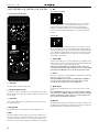 4
4
-
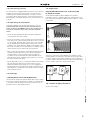 5
5
-
 6
6
-
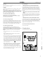 7
7
-
 8
8
-
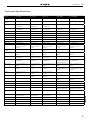 9
9
-
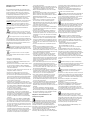 10
10
-
 11
11
-
 12
12
-
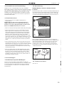 13
13
-
 14
14
-
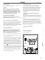 15
15
-
 16
16
-
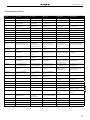 17
17
-
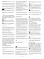 18
18
-
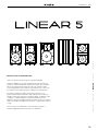 19
19
-
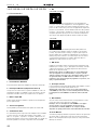 20
20
-
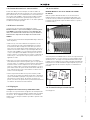 21
21
-
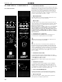 22
22
-
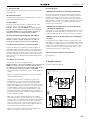 23
23
-
 24
24
-
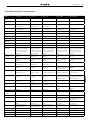 25
25
-
 26
26
-
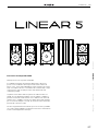 27
27
-
 28
28
-
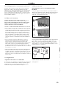 29
29
-
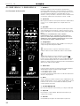 30
30
-
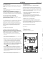 31
31
-
 32
32
-
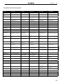 33
33
-
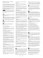 34
34
-
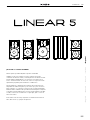 35
35
-
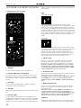 36
36
-
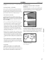 37
37
-
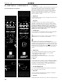 38
38
-
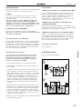 39
39
-
 40
40
-
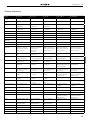 41
41
-
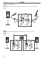 42
42
-
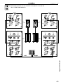 43
43
-
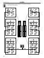 44
44
-
 45
45
-
 46
46
-
 47
47
-
 48
48


HK Audio Linear 5 Manuale utente
- Categoria
- Altoparlanti della soundbar
- Tipo
- Manuale utente
in altre lingue
- English: HK Audio Linear 5 User manual
- français: HK Audio Linear 5 Manuel utilisateur
- español: HK Audio Linear 5 Manual de usuario
- Deutsch: HK Audio Linear 5 Benutzerhandbuch
Documenti correlati
-
HK Audio LINEAR 5 112 XA Manuale utente
-
HK Audio L SUB 2000 A Manuale utente
-
-
-
-
HK Audio LINEAR 3 112 FA Manuale utente
-
-
-
HK Audio E 435 INSTALL KIT Manuale utente
-