
1SVC 630 030 M0000 A2 (01/10)
Printed in the Fed. Rep. of Germany
CT-MXS
CT-WBS
ABB Stotz-Kontakt GmbH
Hauptstr. 14-16
78132 Hornberg / Germany
www.abb.com/lowvoltage -> Control Products -> Electronic Relays and Controls
(D) Betriebs- und Montageanleitung
Elektronische Zeitrelais, CT-S Reihe
Hinweis: Diese Betriebs- und Montageanleitung enthält nicht
sämtliche Detailinformationen zu allen Typen der Produktreihe
und kann auch nicht jeden Einsatzfall der Produkte berück-
sichtigen. Alle Angaben dienen ausschließlich der Produkt-
beschreibung und sind nicht als zugesicherte Eigenschaften
im Rechtssinne aufzufassen.
Weiterführende Informationen
und Daten erhalten Sie in den Katalogen und Datenblättern
der Produkte, über die örtliche ABB-Niederlassung sowie auf
der ABB Homepage unter http://www.abb.com. Technische
Änderungen jederzeit vorbehalten. In Zweifelsfällen gilt der
deutsche Text.
Nur von einer entsprechend qualifizierten Fachkraft zu
installieren. Dabei landesspezifische Vorschriften (z.B.
VDE, etc.) beachten. Vor der Installation diese Be-
triebs- und Montageanleitung sorgfältig lesen und be-
achten. Die Geräte sind wartungsfreie Einbaugeräte.
(GB) Operating and installation instructions
Electronic time relays, CT-S range
Note: These operating and installation instructions cannot
claim to contain all detailed information of all types of this
product range and can even not consider every possible
application of the products. All statements serve exclusively
to describe the product and have not to be understood as
assured characteristics with legal force. Further information
and data is obtainable from the catalogues and data sheets
of this product, from the local ABB sales organisations as
well as on the ABB homepage http://www.abb.com. Subject
to change without prior notice. The German text applies in
cases of doubt.
The device must be installed by qualified persons
only and in accordance with the specific national
regulations (e.g., VDE, etc.). Before installing
this unit, read these operating and installation
instructions carefully and completely. The devices are
maintenance-free chassis-mounted units.
(F) Instructions de service et de montage
Relais électroniques temporisés, gamme CT-S
Note: Ces instructions de service et de montage ne
contiennent pas toutes les informations relatives à tous les
types de cette gamme de produits et ne peuvent pas non
plus tenir compte de tous les cas d’application. Toutes les
indications ne sont données qu’à titre de description du
produit et ne constituent aucunes obligations légales. Pour
de plus amples informations, veuillez-vous référer aux
catalogues et aux fiches techniques des produits, à votre
agence ABB ou à notre site http://www.abb.com. Sous
réserve de modifications techniques. En cas de divergences,
le texte allemand fait foi.
L’installation de ces produits doit être réalisée
uniquement par une personne compétente et en con-
formité avec les prescriptions nationales (p.e. VDE,
etc.). Avant l’installation de cet appareil veuillez lire
l’intégralité de ces instructions. Ces produits sont
des appareils encliquetables qui ne nécessitent pas
d’entretien.
(E) Instrucciones de servicio y de montaje
Temporizadores electrónicos, serie CT-S
Nota: Estas instrucciones no contienen todas las
informaciones detalladas relativas a todos los tipos del
producto ni pueden considerar todos los casos de operación.
Todas las indicaciones son a título descriptivo del producto
y no constituyen obligaciones legales. Para más información,
consulte los catálogos, las hojas de características, la
sucursal local de ABB o la Web http://www.abb.com. Sujeto
a cambios técnicos sin previo aviso. En caso de duda,
prevalece el texto alemán.
La instalación debe llevarse a cabo sólo por personal
especializado. Es necesario respetar las normas
especificas del país (p.ej. VDE, etc.). Antes de la
instalación lea completamente estas instrucciones.
Estos aparatos son equipos para su montaje en
conjuntos y son de libre mantenimiento.
(I) Istruzioni per l’uso ed il montaggio
Relè temporizzatori elettronici, serie CT-S
Nota: Le presenti istruzioni per l’uso ed il montaggio non
contengono tutte le informazioni dettagliate su tutta la gamma
di prodotti e non possono trattare tutti i casi applicativi. Tutte
le indicazioni servono esclusivamente a descrivere il prodotto
e non sono da interpretare come caratteristiche garantite
con valore di legge. Per ulteriori informazioni consultare i
cataloghi ed i data sheet dei prodotti, o la nostra homepage
http://www.abb.com, oppure rivolgersi alla locale filiale ABB.
Ci riserviamo di eventuali modifiche tecniche. In caso di
differenze o problemi è valido il testo tedesco.
Installazione solo a cura di personale specializzato.
Bisogna osservare le specifiche norme nazionali
(p.e. VDE, etc.). Prima dell’installazione leggere
attentamente le seguenti istruzioni. Questi prodotti
sono apparecchi ad incasso, che non hanno bisogno
di manutenzione.
(CN) ֡ፕᇑҾጎኸళ
ۉጱ้क़ीۉഗ
CT-S ဣଚ
ጀᅪǖԨ֡ፕኸళփԈࡤरຍຕࢅඇևׂᆌᆩຫLjᆶ
ຕኻਏᆶܔׂ༬ႠႜຫڦፕᆩLjᅺُփਏԢ݆ୱၳ
ᆌăၘဦຫ൩֖ለरຍᄣԨईஏABBړںӸ๚تई៓બ
BCCྪበDŽhttp://www.abb.comDžăසᆶ߸߀Ljທփཚኪăժ
ᅜڤ࿔ྺՔጚă
ഗॲՂႷᆯጆᄽටᇵӀቷࡔाጆᄽࡀቤҾጎDŽස
VDEDžăҾጎമLj൩ံၘဦለ܁ԨҾጎኸళă
ׂڹಎփࡤඪࢆႴᄲҾጎڦևݴLj൩փᄲٶਸڹ
ಎăׂُྺ௨ྼࢺڹӱҾጎഗॲă

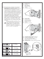
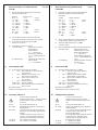
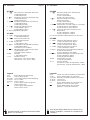
(D) Plombierbare Klarsichtabdeckung anbringen
(GB) Fix sealable transparent cover
(F) Fixation du capot transparent condamnable
(E) Fijar cubierta transparente sellable
(I) Fissare la copertura trasparente sigillabile
(CN)
(RU)
(D) Produkt anbringen
(GB) Fix product
(F) Monter le produit
(E) Fijar el producto
(I) Montare il prodotto
(CN)
(RU)
(D) Produkt entfernen
(GB) Remove product
(F) Démonter le produit
(E) Desmontar el producto
(I) Rimuovere il prodotto
(CN)
(RU)
2CDC 252 146 F0006 2CDC 252 282 F0005 2CDC 252 281 F0005
2
# 8SWXVYP\NdUTYWXFSTHPKNbPWUQYFXF\NN
EQKPXVTSSTKVKQKHVKRKSNWKVNd?@!
%!," <FWXTd_Fd NSWXVYP\Nd UT YWXFSTH
PK N bPWUQYFXF\NN SK UVKXKSJYKX SF UTQSTXY
WTJKVLF_KOWd MJKWa NSZTVRF\NN UT HWKR XNUFR
WKVNN SFWXTd_KIT NMJKQNd N JFLK SK VFWWRFXVN
HFKX HWK HTMRTLSTWXN UVNRKSKSNd SFWXTd_KIT
NMJKQNd 4Wd NSZTVRF\Nd WQYLNX NWPQc]NXKQaST
JQd KIT TUNWFSNd N SK JTQLSF VFWWRFXVNHFXaWd H
PF]KWXHK IFVFSXNVTHFSS`[ [FVFPXKVNWXNP NRK
c_N[ cVNJN]KWPYc WNQY 6TUTQSNXKQaSYc
NSZTVRF\Nc N JFSS`K RTLST UTQY]NXa NM
PFXFQTITH N :NWXTH JFSS`[ SF SFWXTd_KK
NMJKQNK H RKWXSTR UVKJWXFHNXKQaWXHK PTRUFSNN
344 F XFPLK SF WFOXK PTRUFSNN 344 UT FJVKWY
,11/222)**+.- 4TMRTLS` NMRKSKSNd GKM
UVKJHFVNXKQaSTIT YHKJTRQKSNd =VN HTMSNPST
HKSNN WTRSKSNO XKPWX SF SKRK\PTR dM`PK NRKKX
UVNTVNXKX
AWXVTOWXHT UTJQKLNX YWXFSTHPK XTQaPT
PHFQNZN\NVTHFSS`R UKVWTSFQTR H WTTXHKX
WXHNN W SF\NTSFQaS`RN XVKGTHFSNdRN
SFUVNRKV $ N XJ =KVKJ SF]FQTR
YWXFSTHPN JFSSTIT NMJKQNd UTQSTWXac N
HSNRFXKQaST UVT]NXFOXK NSWXVYP\Nc UT
YWXFSTHPK AWXVTOWXHT YWXFSFHQNHFKXWd SF
^FWWN N SK XVKGYKX TGWQYLNHFSNd
p
AWXFSTHPF YWXVTOWXHF
6KRTSXFL YWXVTOWXHF
ppg
AWXFSTHPF TUK]FX`HFKRTO UVTMVF]STO PV`^PN
7 mm
0.28 in
7 mm
0.28 in
7 mm
0.28 in
2 x 0.5...4 mm²
2 x 20...12 AWG
Ø 4.5 mm / 0.177 in / PH 1
0.6...0.8 Nm
5.31...7.08 lb.in
2 x 0.75...2.5 mm²
2 x 18...14 AWG
2 x 0.75...2.5 mm²
2 x 18...14 AWG
2CDC 252 047 F0b09
g
ssa e a cope u a
ཪހ߃ڦҾጎ
ׂႂጎ
ׂҾጎ

2
1
I
2CDC 252 143 F0006
2CDC 252 144 F0006
4
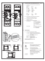
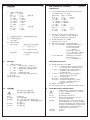
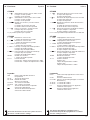
I Frontansichten mit Bedienelementen
/ Einstellung des Zeitbereiches durch Wahl des
Endwertes
Bereich Endwert
0,15 - 3 s >> 3 s gelbe
1,5 - 30 s >> 30 s Skala
15 - 300 s >> 300 s
1,5 - 30 min >> 30 min
15 - 300 min >> 300 min
1,5 - 30 h >> 30 h
15 - 300 h >> 300 h
0,05 - 1 s >> 1 s weiße
0,5 - 10 s >> 10 s Skala
5 - 100 s >> 100 s
0 Absolutskala zur Einstellung des Zeitwertes
innerhalb des gewählten Bereiches
1 Auswahl der Funktion bei CT-WBS
Funktionen siehe IV
2 Betriebszustandsanzeige mit LEDs
U/T: LED grün - Anzeige Steuerspeise-
spannung und Zeitablauf
V Steuerspeise-
spannung liegt an
W Verzögerungszeit
läuft
R: LED gelb - Anzeige der Schaltstellung
des Ausgangsrelais
V angezogen
II DIP Schalter
3 Auswahl der Funktion bei CT-MXS
1 ON = Einzeltaktgeber, pausebeginnend
2 ON = Ansprech- und Rückfallverzögerung,
asymmetrisch
3 ON = Ein- und Ausschaltwischer
4 ON = keine Funktion
All ON = ON/OFF-Funktion
All OFF = Taktgeber, impuls- oder
pausebeginnend
Auslieferungszustand:
Alle DIP-Schalter in Position OFF
III Elektrischer Anschluss
Bemessungssteuerspeisespannung
und Schaltbild dem seitlichen
Typenschild am Gerät entnehmen
A1-A2 Steuerspeisespannung U
s
A1-Y1/B1 Steuereingang für Zeitstart
Z2-Z3/Z1 1./2. Fernpotentiometeranschluss zur
Zeitfeineinstellung.
Bei Anschluss eines externen Potentio-
meters wird das entsprechende
interne, frontseitige Potentiometer
automatisch abgeschaltet.
15-16/18 1. Wechsler
25-26/28 2. Wechsler
Deutsch
2CDC 252 284 F0005
III
2
5
1
2
4
3
1
3
II

English
Français
I Front view with operating controls
/ Adjustment of the time range by selecting the
max. value
Range Max. value
0.15 - 3 s >> 3 s yellow
1.5 - 30 s >> 30 s dial
15 - 300 s >> 300 s
1.5 - 30 min >> 30 min
15 - 300 min >> 300 min
1.5 - 30 h >> 30 h
15 - 300 h >> 300 h
0.05 - 1 s >> 1 s white
0.5 - 10 s >> 10 s dial
5 - 100 s >> 100 s
0 Direct reading scale to set the time value within
the chosen range
1 Selection of the function on CT-WBS
Functions: see IV
2 Status display with LEDs
U/T: green LED - Status indication of control
supply voltage and timing
V Control supply
voltage applied
W Time delay is
running
R: yellow LED - Status indication of output
relay
V energized
II DIP switches
3 Selection of the function on CT-MXS
1 ON = Single pulse generator, starting with OFF
2 ON = ON-delay and OFF-delay, asymmetrical
3 ON = Impulse-ON and impulse-OFF
4 ON = no function
All ON = ON/OFF-Function
All OFF = Pulse generator, starting with ON or OFF
State of delivery:
All DIP switches in position OFF
III Electrical connection
For the rated control supply voltage
and the circuit diagram, see label at
the side of the unit
A1-A2 Control supply voltage U
s
A1-Y1/B1 Control input to start timing
Z2-Z3/Z1 1st/2nd remote potentiometer
connection for the fine adjustment of
the time delay.
When an external potentiometer is
connected, the corresponding internal,
front-face potentiometer is disabled.
15-16/18 1st c/o contact
25-26/28 2nd c/o contact
I Face avant et dispositifs de
commande
/ Réglage de la plage de temporisation par
sélection de la valeur maximale
Plage Valeur maximale
0,15 - 3 s >> 3 s échelle
1,5 - 30 s >> 30 s jaune
15 - 300 s >> 300 s
1,5 - 30 min >> 30 min
15 - 300 min >> 300 min
1,5 - 30 h >> 30 h
15 - 300 h >> 300 h
0,05 - 1 s >> 1 s échelle
0,5 - 10 s >> 10 s blanche
5 - 100 s >> 100 s
0 Valeur absolue pour le réglage de la
temporisation à l’intérieur de la plage choisie.
1 Sélection de la fonction pour CT-WBS
Pour les fonctions, voir IV
2 Indication de fonctionnement par LED
U/T: LED verte - Indication de la tension
d’alimentation de
commande et temporisation
V Tension
d’alimentation de
commande appliquée
W Temporisation en
cours
R: LED jaune - Indication de l’état du relais
de sortie
V activé
II Micro-interrupteurs
3 Sélection de la fonction pour CT-MXS
1 ON = Générateur d’impulsion unique,
démarrant par arrêt
2 ON = Temporisation Travail et Repos,
asymétrique
3 ON = Contact de passage à l’activation et
à la désactivation
4 ON = pas de fonction
Tous ON = Fonction ON/OFF
Tous OFF = Générateur d’impulsion, démarrant
par marche ou par arrêt
Etat de livraison:
Tous les micro-interrupteurs en position OFF
III Raccordement électrique
Pour la tension assignée
d’alimentation de commande et pour
le schéma des connexions voir
l’étiquette placée sur le côté du relais.
A1-A2 Tension d’alimentation de commande U
s
A1-Y1/B1 Entrée de commande pour le
démarrage de la temporisation
Z2-Z3/Z1 1er/2ème raccordement pour
potentiomètre déporté pour le réglage
fin de la temporisation.
Quand un potentiomètre externe est
raccordé, le potentiomètre interne
correspondant, sur la face avant, est
automatiquement désactivé.
15-16/18 1er inverseur
25-26/28 2ème inverseur
4

Español Italiano
I Vistas frontales con elementos de
mando
/ Ajuste del margen de tiempo para selección
del valor fondo escala
Margen Fondo escala
0,15 - 3 s >> 3 s escala
1,5 - 30 s >> 30 s amarilla
15 - 300 s >> 300 s
1,5 - 30 min >> 30 min
15 - 300 min >> 300 min
1,5 - 30 h >> 30 h
15 - 300 h >> 300 h
0,05 - 1 s >> 1 s escala
0,5 - 10 s >> 10 s blanca
5 - 100 s >> 100 s
0 Escala absoluta para el ajuste del valor de
temporización dentro de margen seleccionado
1 Selección de la función para CT-WBS
Funciones: vease IV
2 Indicador de servicio con LEDs
U/T: LED verde - Indicación tensión de
alimentación
y
temporización
V Tensión de
alimentación
aplicada
W Temporización en
curso
R: LED amarillo - Indicación del estado del
relé de salida
V energizado
II Interruptores DIP
3 Selección de la función para CT-MXS
1 ON = Generador de un único impulso,
inicio en OFF
2 ON = Retardo a la conexión y a la
desconexión, asimétrico
3 ON = Pulso a la conexión y a la
desconexión
4 ON = ninguna función
Todos ON = Función ON/OFF
Todos OFF = Generador de pulsos, arranque en
ON ó en OFF
Entrega de fábrica:
Todos los interruptores DIP en posición OFF
III Conexión eléctrica
Véase la etiqueta lateral de
características para la tensión nominal
de
alimentación y para el esquema
contactos
A1-A2 Tensión de alimentación
U
s
A1-Y1/B1 Entrada de mando para el inicio de la
temporización
Z2-Z3/Z1 1era/2da conexión del potenciometro
remoto para el ajuste fino del tiempo de
retardo.
Cuando un potenciometro externo se
conecta, el correspondiente potencio-
metro interno del
frontal se desactiva.
15-16/18 1er. contacto conmutado
25-26/28 2do. contacto conmutado
I Vista frontale con gli elementi di
comando
/ Impostazione del campo di temporizzazione
mediante selezione del valore massimo
del campo
Campo Valore massimo
0,15 - 3 s >> 3 s scala
1,5 - 30 s >> 30 s gialla
15 - 300 s >> 300 s
1,5 - 30 min >> 30 min
15 - 300 min >> 300 min
1,5 - 30 h >> 30 h
15 - 300 h >> 300 h
0,05 - 1 s >> 1 s scala
0,5 - 10 s >> 10 s bianca
5 - 100 s >> 100 s
0 Scala a lettura diretta per l’impostazione del
tempo all’interno del campo selezionato
1 Selezione della funzione per CT-WBS
Funzioni: vedi IV
2 LED di visualizzazione dello stato di funzionamento
U/T: LED verde - Indicazione tensione
d’alimentazione e stato
della temporizzazione
V Tensione
d’alimentazione applicata
W Temporizzazione in
corso
R: LED giallo - Indicazione dello stato del
relè d’uscita
V eccitato
II Interruttori DIP
3 Selezione della funzione per CT-MXS
1 ON = Generatore di singolo impulso,
inizio con OFF
2 ON = Ritardo all’eccitazione ed alla
diseccitazione, asimmetrico
3 ON = Impulso all’eccitazione ed alla
diseccitazione
4 ON = senza funzione
Tutti ON = Funzione ON/OFF
Tutti OFF = Generatore di impulsi, inizio con
ON o OFF
Impostazione di fabbrica:
Tutti interruttori DIP in posizione OFF
III Collegamento elettrico
Per la tensione nominale
d’alimentazione e per lo schema
elettrico, vedi la targhetta laterale del
relè.
A1-A2 Tensione d’alimentazione U
s
A1-Y1/B1 Ingresso di comando per lo start della
temporizzazione
Z2-Z3/Z1 1°/2° connessione per il potenziometro
a distanza per la regolazione di
precisione del tempo.
Il corrispondente potenziometro interno,
sul lato frontale, si disattiva auto-
maticamente al collegamento del
potenziometro esterno.
15-16/18 1° contatto di scambio
25-26/28 2° contatto di scambio
5

6
>YWWPNO
&$%" 0 !"'.
($% "2
>KIYQNVTHPF HVKRKSSTIT JNFUFMTSF UYXKR
YWXFSTHPN RFPW MSF]KSNd
6NFUFMTS ;FPW MSF]KSNK
W W LKQXFd
W W ^PFQF
W W
RNS RNS
RNS RNS
] ]
] ]
W W GKQFd
W W ^PFQF
W W
CPFQF H FGWTQcXS`[ MSF]KSNd[ JQd
YWXFSTHPN XT]STIT MSF]KSNd HVKRKSN
H UVKJKQF[ H`GVFSSTIT JNFUFMTSF
4`GTV ZYSP\NN SF "%!
BYSP\NN WR IQFHY $
6NWUQKO WTWXTdSNd WT WHKXTJNTJFRN
#"MKQKS`O ?86 8SJNPF\Nd WTWXTdSNd
SFUVdLKSNd UNXFSNd
N TXW]KXF HVKRKSN
V =TJFST
SFUVdLKSNK UNXFSNd
W 8JKX TXW]KX HVKRK
SN WVFGFX`HFSNd VKQK
LKQX`O ?86 8SJNPF\Nd WTWXTdSNd
H`[TJSTIT VKQK
V FPXNHNVTHFST
$% 1,'
4`GTV ZYSP\NN SF "&!
5KSKVFXTV TJNST]S`[ NRUYQaWTH
SF]FQT TXW]KXF W HVKRKSN UFYM`
4`JKVLPF UVN WVFGFX`HFSNN N
H`JKVLPF UVN TXUYWPFSNN
FWWNRKXVN]SFd
8RUYQaW UVN WVFGFX`HFFSNN N
NRUYQaW UVN TXUYWPFSNN
SKX ZYSP\NN
4WK ZYSP\Nd 49:4D9:
4WK 5KSKVFXTV NRUYQaWTH SF]FQT
TXW]KXF W HVKRKSN NRUYQaWF
NQN HVKRKSN UYFM`
?TWXTdSNK UTWXFHPN
4WK UKVKPQc]FXKQN H UTQTLKSNN 4D9:
'%,&# $# 1,"
<TRNSFQaSTK SFUVdLKSNK UNXFSNd
N W[KRY WTKJNSKSNO WR SF bXNPKXPK
SF GTPY UVNGTVF
<FUVdLKSNK UNXFSNd #
0
' AUVFHQdc_NO H[TJ JQd MFUYWPF
HVKRKSS`[ ZYSP\NO
((( =TJWTKJNSKSNK ITIT H`STWSTIT
UTXKS\NTRKXVF JQd XTSPTO SFWXVTOPN
HVKRKSN MFJKVLPN =VN UTJPQc]KSNN
HSK^SKIT UTXKS\NTRKXVF HWXVTKSS`O
UTXKS\NTRKXV SF QN\KHTO UFSKQN
FHXTRFXN]KWPN TXPQc]FXKWd
`O UP
TO UP
I മ௬ӱ֡ፕ CN
ۙব้क़ݔྷፌٷኵ
ݔྷ ፌٷኵ
0.15 - 3 s >> 3 s ࣜਗ਼܈
1.5 - 30 s >> 30 s
15 - 300 s >> 300 s
1.5 - 30 min >> 30 min
15 - 300 min >> 300 min
1.5 - 30 h >> 30 h
15 - 300 h >> 300 h
0.05 - 1 s >> 1 s ӣਗ਼܈
0.5 - 10 s >> 10 s
5 - 100 s >> 100 s
ሞስڦ้क़ݔྷాLj܁ਗ਼܈ಎย้ۨक़ኵ
CT-WBSࠀీስ
! ! ࠀీ;֖ੂJW
LEDs!ጒༀኸ๖
U/T:!LED - ࠃۉۉუࢅऺ้ጒༀኸ๖!
V!ࠃۉۉუฉۉ
W!ၚᆌჽ้Tvᆶၳ
R:ࣜLED - ीۉഗۯፕጒༀኸ๖!
V ۯፕ
II DIP ਸ࠲
ስCT-MXSࠀీ
1 ON = ڇஞ؋݀ิഗLjᅜOFFਸ๔
2 ON = ཚ/ۉჽ้Ljჽ้้क़փ၎ڪ
3 ON = ཚۉஞ؋ჽ้ࢅۉஞ؋ჽ้
4 ON = ᆖၚ
ᆶ ON = ON/OFF֪ࠀీ
ᆶ!OFF = ஞ؋݀ิഗLjᅜONईOFFਸ๔
ఐණ࿋ዃ:
ᆶਸ࠲تᇀOFFጒༀ
III ۉഘথ
၎࠲ڦࠃۉۉუࢅথ၍࣮ୟLj
! ! ൩֖ੂ้क़ीۉഗ֨௬ڦՔധ!
A1-A2 Usࠃۉۉუ
A1-Y1/B1 ऺ้ਸ๔੦
Z2-Z3/Z1 ڼᅃĂڼܾᇺײۉ࿋ऺۙবჽ้क़
! ! ړྔথᇺײۉ࿋ऺࢫLjीۉഗമ௬ӱ้ۨۉ!
! ! ࿋ऺ฿ၳ
15-16/18 ڼᅃةۅ
25-26/28 ڼܾةۅ

A1-A2
A1-Y1/B1
15-16, 25-26
15-18, 25-28
t
1
t
1
t
2
t
2
2CDC 252 075 F0207
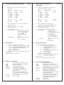
green LED
t
1
= adjusted OFF time
t
2
= adjusted ON time
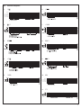
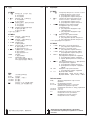
IV Function diagrams
1 DE
2 EC
3 AB
4 CE
5 DA
6 DB
7 CA
8 AC
9 BC
10 A
A1-A2
15-16, 25-26
15-18, 25-28
t< t
2CDC 252 013 F0207
green LED
t = adjusted time delay
11 G
7

8

IV Funktionen
CT-MXS
1 DE Taktgeber, impuls- oder pausebeginnend
t1 eingestellte Pausenzeit
t2 eingestellte Impulszeit
2 EC Einzeltaktgeber, pausebeginnend
t1 eingestellte Pausenzeit
t2 eingestellte Impulszeit
3 AB Ansprech- und Rückfallverzögerung,
asymmetrisch
t1 eingestellte Ansprechverzögerungszeit
t2 eingestellte Rückfallverzögerungszeit
4 CE Ein- und Ausschaltwischer
t1 eingestellte Wischzeit 1
t2 eingestellte Wischzeit 2
t1 und t2 sind unabhängig voneinander einstellbar
CT-WBS
5 DA Blinker, impulsbeginnend
t eingestellte Blinkzeit
6 DB Blinker, pausebeginnend
t eingestellte Blinkzeit
7 CA Einschaltwischer
t eingestellte Wischzeit
8 AC Verzögerter fester Impuls
t1 eingestellte Verzögerungszeit
t2 Impulszeit fix 500 ms
9 BC Einstellbarer Impuls, fest verzögert
t1 eingestellte Impulszeit
t2 Verzögerungszeit fix 500 ms
10 A Ansprechverzögerung
t eingestellte Verzögerungszeit
11 G ON/OFF-Funktion
ON-Funktion - Zeitbereich ≠ 300 h
OFF-Funktion - Zeitbereich = 300 h
Legende:
LED grüne LED blinkt während Zeitfablauf
A1-A2 Steuerspeisespannung
A1-Y1/B1 Steuereingang (potentialbehaftete Ansteuerung)
15-16/18 1. Wechsler
25-26/28 2. Wechsler
G Steuerspeisespannung liegt nicht an /
Ausgangskontakt geöffnet
B Steuerspeisespannung liegt an /
Ausgangskontakt geschlossen
Deutsch
9
Weitere Details zu den Funktionen und den
technischen Daten entnehmen Sie bitte dem Katalog.

English
Français
IV Functions
CT-MXS
1 DE Pulse generator, starting with ON or OFF
t1 adjusted OFF time
t2 adjusted ON time
2 EC Single pulse generator, starting with OFF
t1 adjusted OFF time
t2 adjusted ON time
3 AB ON-delay and OFF-delay, asymmetrical
t1 adjusted ON-delay
t2 adjusted OFF-delay
4 CE Impulse-ON and impulse-OFF
t1 adjusted pulse time 1
t2 adjusted pulse time 2
t1 are t2 independently adjustable
CT-WBS
5 DA Flasher, starting with ON
t adjusted flashing time
6 DB Flasher, starting with OFF
t adjusted flashing time
7 CA Impulse-ON
t adjusted pulse time
8 AC Fixed impulse with adjustable time delay
t1 adjusted time delay
t2 fixed pulse time of 500 ms
9 BC Adjustable impulse with fixed time delay
t1 adjusted pulse time
t2 fixed time delay of 500 ms
10 A ON-delay
t adjusted time delay
11 G ON/OFF-Function
ON-Function - time sector ≠ 300 h
OFF-Function - time sector = 300 h
Legend:
LED Green LED flashes whilst timing
A1-A2 Control supply voltage
A1-Y1/B1 Control input (voltage-related triggering)
15-16/18 1st c/o contact
25-26/28 2nd c/o contact
G Control supply voltage not applied /
output contact open
B Control supply voltage applied /
output contact closed
IV Fonctions
CT-MXS
1 DE Générateur d’impulsion, démarrant par
marche ou par arrêt
t1 temps d’arrêt affiché
t2 temps de marche affiché
2 EC Générateur d’impulsion unique,
démarrant par arrêt
t1 temps d’arrêt affiché
t2 temps de marche affiché
3 AB Temporisation au travail et Repos, asymétrique
t1 temporisation au travail affichée
t2 temporisation au repos affichée
4 CE Contact de passage à l’activation et à la
désactivation
t1 temps d’impulsion 1 affiché
t2 temps d’impulsion 2 affiché
t1 et t2 sont affichables indépendamment un de l’autre
CT-WBS
5 DA Clignotant, démarrant par marche
t temps de clignotement affiché
6 DB Clignotant, démarrant par arrêt
t temps de clignotement affiché
7 CA Contact de passage à l’activation
t temps d’impulsion affiché
8 AC Impulsion fixe avec temporisation affichable
t1 temporisation affichée
t2 temps d’impulsion fixe 500 ms
9 BC Impulsion affichable avec temporisation fixe
t1 temps d’impulsion affiché
t2 temporisation fixe 500 ms
10 A Temporisation au travail
t temporisation affichée
11 G Fonction ON/OFF
Fonction ON - plage de temporisation ≠ 300 h
Fonction OFF - plage de temporisation = 300 h
Légende:
LED La LED verte clignote pendant la temporisation
A1-A2 Tension d’alimentation de commande
A1-Y1/B1 Entrée de commande (activation par tension)
15-16/18 1er inverseur
25-26/28 2ème inverseur
G Tension d’alimentation de commande non
appliquée / contact de sortie ouvert
B Tension d’alimentation de commande
appliquée / contact de sortie fermé
10
For further details on functions and technical data,
please see our catalog.
Pour de plus amples détails sur les fonctions et les
données techniques, consultez s’il vous plaît, notre
catalogue.

Español Italiano
IV Funciones
CT-MXS
1 DE Generador de impulso, inicio en ON ó en OFF
t1 tiempo en OFF ajustado
t2 tiempo en ON ajustado
2 EC Generador de un único pulso, inicio en OFF
t1 tiempo en OFF ajustado
t2 tiempo en ON ajustado
3 AB Retardo a la conexión y a la desconexión,
asimétrico
t1 retardo a la connexion ajustado
t2 retardo a la desconnexion ajustado
4 CE Pulso a la conexión y a la desconexión
t1 tiempo de pulso 1 ajustado
t2 tiempo de pulso 2 ajustado
t1 y t2 pueden ajustarse por separado
CT-WBS
5 DA Intermitencia, inicio en ON
t tiempo de intermitencia ajustado
6 DB Intermitencia, inicio en OFF
t tiempo de intermitencia ajustado
7 CA Pulso a la conexión
t tiempo de pulso ajustado
8 AC Pulso fijo con tiempo de retardo ajustable
t1 tiempo de retardo ajustado
t2 tiempo de pulso fijo de 500 ms
9 BC Pulso ajustable con tiempo de retardo fijo
t1 tiempo de pulso ajustado
t2 tiempo de retardo fijo de 500 ms
10 A Retardo a la conexión
t tiempo de retardo ajustado
11 G Función ON/OFF
Función ON - margen de temporización ≠ 300 h
Función OFF - margen de temporización = 300 h
Leyenda:
LED El LED verde parpadea durante la
temporización
A1-A2 Tensión de alimentación
A1-Y1/B1 Entrada de mando
(disparo con potencial)
15-16/18 1er. contacto conmutado
25-26/28 2do. contacto conmutado
G Tensión de alimentación no
aplicada /
contacto de salida abierto
B Tensión de alimentación
aplicada /
contacto de salida cerrado
IV Funzioni
CT-MXS
1 DE Generatore di impulsi, inizio con ON o OFF
t1 tempo OFF impostato
t2 tempo ON impostato
2 EC Generatore di singolo impulso, inizio con OFF
t1 tempo OFF impostato
t2 tempo ON impostato
3 AB Ritardo all’eccitazione ed alla diseccitazione,
asimmetrico
t1 ritardo all’eccitazione impostato
t2
ritardo alla diseccitazione impostato
4 CE Impulso all’eccitazione ed alla diseccitazione
t1 tempo d’impulso 1 impostato
t2 tempo d’impulso 2 impostato
t1 e t2 sono impostabile indipendentemente uno dell’altro
CT-WBS
5 DA Lampeggiatore, inizio con ON
t tempo di lampeggiamento impostato
6 DB Lampeggiatore, inizio con OFF
t tempo di lampeggiamento impostato
7 CA Impulso all’eccitazione
t tempo d’impulso impostato
8 AC Impulso fisso con tempo di ritardo impostabile
t1 tempo di ritardo impostato
t2 tempo d’impulso fisso 500 ms
9 BC Impulso impostabile con tempo di ritardo fisso
t1 tempo d’impulso impostato
t2 tempo di ritardo fisso 500 ms
10 A Ritardo all’eccitazione
t tempo di ritardo impostato
11 G Funzione ON/OFF
Funzione ON -
campo di temporizzazione ≠ 300 h
Funzione OFF -
campo di temporizzazione = 300 h
Leggenda:
LED Il LED verde lampeggia durante il trascorrere
del tempo
A1-A2 Tensione d’alimentazione
A1-Y1/B1 Ingresso di comando (pilotaggio con tensione
di riferimento )
15-16/18 1° contatto di scambio
25-26/28 2° contatto di scambio
G Tensione d’alimentazione non applicata /
contatto d’uscita aperto
B Tensione d’alimentazione applicata /
contatto d’uscita chiuso
11
Para más información en funciones y datos técnicos,
por favor consulte nuestro catálogo.
Per ulteriori informazioni su dettagli tecnici e
funzionalità dei prodotti Vi preghiamo di consultare
il nostro catalogo tecnico.

12
("+
DE 5KSKVFXTV NRUYQaWTH SF]FQT TXW]KXF
W HVKRKSN NRUYQaWF NQN UFYM`
1 VKIYQNVYKRTK HVKRd UFYM`
1 VKIYQNVYKRTK HVKRd NRUYQaWF
EC 5KSKVFXTV TJNST]S`[ NRUYQaWTH
SF]FQT TXW]KXF W HVKRKSN UFYM`
1 VKIYQNVYKRTK HVKRd UFYM`
1 VKIYQNVYKRTK HVKRd NRUYQaWF
AB 4`JKVLPF UVN WVFGFX`HFSNN
N H`JKVLPF UVN TXUYWPFSNN
FWWNRKXVN]SFd
1 VKIYQNVYKRFd H`JKVLPF UVN
WVFGFX`HFSNN
1 VKIYQNVYKRFd H`JKVLPF UVN
TXUYWPFSNN
CE 8RUYQaW UVN WVFGFX`HFSNN
N NRUYQaW UVN TXUYWPFSNN
1 VKIYQNVYKRTK HVKRd NRUYQaWF
1 VKIYQNVYKRTK HVKRd NRUYQaWF
1 N 1 VKIYQNVYcXWd TXJKQaST
DA ;NIFSNK W SF]FQTR NRUYQaWF
1 VKIYQNVYKRTK HVKRd RNIFSNd
DB ;NIFSNK W SF]FQTR UFYM`
1 VKIYQNVYKRTK HVKRd RNIFSNd
CA 8RUYQaW UVN WVFGFX`HFSNN 49:
1 VKIYQNVYKRTK HVKRd NRUYQaWF
AC BNPWNVYKR`O NRUYQaW W
VKIYQNVYKR`R HVKRKSKR MFJKVLPN
1 VKIYQNVYKRTK HVKRd MFJKVLPN
1 HVKRd ZNPWNVTHFSSTIT NRUYQaWF
RW
BC >KIYQNVYKR`O NRUYQaW W ZNPWNVTHFS
S`R HVKRKSKR MFJKVLPN
1 VKIYQNVYKRTK HVKRd NRUYQaWF
1 ZNPWNVTHFSSTK HVKRd MFJKVLPN
RW
A 7FJKVLPF UVN WVFGFX`HFSNN
1 VKIYQNVYKRTK HVKRd MFJKVLPN
G BYSP\Nd 49:4D9:
BYSP\Nd 49: HVKR WKPXTV ]
BYSP\Nd 4D9: HVKR WKPXTV ]
#","2
?86 7KQKS`O ?86 RNIFKX UVN TXW]KXK
HVKRKSN
<FUVdLKSNK UNXFSNd
' AUVFHQdc_NO H[TJ W MFUYWPTR
HVKRKSS`[ ZYSP\NO UTJF]KO
SFUVdLKSNd UNXFSNd SF H[TJ YUVFHQKSNd
`O UP
TO UP
G <FUVdLKSNK UNXFSNd TXWYXWXHYKX
H`[TJSTO PTSXFPX VFMTRPSYX
B <FUVdLKSNK UNXFSNd UTJFST
H`[TJSTO PTSXFPX MFRPSYX
>YWWPNO
#$# "' /"(1")#%!+1#)("+2*
'*",&*$%!'%* &!"-!
' #
IV ࠀీ!!!!! DO!
CT-MXS
1 DE ஞ؋݀ิഗLjᅜpoईpgg!ਸ๔
t1 off ้क़ۙব
t2 on ้क़ۙব
2 EC ڇஞ؋݀ิഗLjᅜOFFਸ๔
t1 off ้क़ۙব
t2 on ้क़ۙব
3 AB ཚ/ۉუჽ้Ljჽ้้क़փ၎ڪ
t1 on ้क़ۙব
t2 off ้क़ۙব
4 CE ཚۉஞ؋ჽ้ࢅۉஞ؋ჽ้
t1 ஞ؋้क़2ۙব
t2 ஞ؋้क़3ۙব
t1 t2 ܀૬ڦۙব
CT-WBS
5 DA ཚۉຮLjᅜଋༀONਸ๔
t ຮ้क़ۙব
6 DB ཚۉຮLjᅜӁༀOFFਸ๔
t ຮ้क़ۙব
7 CA ཚۉஞ؋ჽ้
t ஞ؋้क़ۙব
8 AC ჽ้้क़ۙLjࠦۨஞ؋้क़
t1 ჽ้้क़ۙব
!! t2 ࠦۨஞ؋้क़611!nt
9 BC ۙஞ؋้क़Ljࠦۨჽ้้क़
t1 ஞ؋้क़ۙব
!! t2 ࠦۨჽ้้क़611!nt
10 A ཚۉჽ้
t ჽ้क़ۙব
11 G ON/OFF֪ࠀీ
ON -ࠀీ-้क़ਗ਼܈ 300ၭ้
OFF-ࠀీ-้क़ਗ਼܈= 300ၭ้
๖:
LED ऺ้ዐ୴LEDຮ
A1-A2 ࠃۉۉუ
A1-Y1/B1 ੦DŽ߅থۅDž
15-16/18 ڼᅃةۅ
25-26/28 ڼܾةۅ
G ࠃۉۉუ࿄ฉۉ / ةۅਸ
B ࠃۉۉუฉۉ / ةۅԿࢇ
߸ܠࠀీ႑တतरຍጨଙLj൩֖ੂᄣԨă
-
 1
1
-
 2
2
-
 3
3
-
 4
4
-
 5
5
-
 6
6
-
 7
7
-
 8
8
-
 9
9
-
 10
10
-
 11
11
-
 12
12


ABB CT-WBS Istruzioni per l'uso
- Tipo
- Istruzioni per l'uso
- Questo manuale è adatto anche per
in altre lingue
- English: ABB CT-WBS Operating instructions
- français: ABB CT-WBS Mode d'emploi
- español: ABB CT-WBS Instrucciones de operación
- Deutsch: ABB CT-WBS Bedienungsanleitung
Documenti correlati
-
ABB CT-C Series Istruzioni per l'uso
-
-
ABB CM Series Istruzioni per l'uso
-
-
-
-
-
-
-
Altri documenti
-
Planet WBS-900AC-KIT Manuale utente
-
Planet WBS-512AC Manuale utente
-
SBC KOP.J electronic timer Scheda dati
-
Schneider Electric RM35LM33MW Istruzioni per l'uso
-
Eaton EMR5-AWM580-2 Istruzioni per l'uso
-
-
CARLO GAVAZZI PCB01DM24 Guida d'installazione
-
-
Omega SSRDIN280 and SSRDIN600 Manuale del proprietario
-
THEBEN Elpa 041 Manuale del proprietario