HIKMICRO Heat-resistant Bullet Cameras Guida Rapida
- Tipo
- Guida Rapida

Heat Resistant Bullet Camera
Quick Start Guide

Heat Resistant Bullet Camera · Quick Start Guide
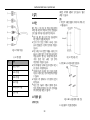
Table of Contents
English
1
Polski
53
Bahasa Indonesia
107
Deutsch
6
Română
59
Français
11
Slovenčina
64
Español
17
ျမန္မာ
69
Italiano
22
Türkçe
76
Português
27
Русский
81
Nederlands
33
Українська
86
Čeština
38
繁體中文
92
Dansk
43
한국어
97
Magyar
48
日本語
102

Heat Resistant Bullet Camera · Quick Start Guide
1
English
1 Preparation
Basic Requirement
● All the electronic operation should be strictly compliance
with the electrical safety regulations, fire prevention
regulations and other related regulations in your local region.
● Check the package contents and make sure that the device in
the package is in good condition and all the assembly parts
are included.
● Use the system according to the working environment
requirement.
Checking Installing Environment
● Be sure that there is enough space to install the camera and
accessories.
● Make sure that the wall is strong enough to withstand at
least 8 times the weight of the camera and the mount.
Preparing Cables
● According to the actual network bandwidth, the Cat5 (in
100 M) or Cat6 (100 M above) is needed.
● When the camera uses standard 12 VDC power supply, the
power cable should be American wire gauge 18 or above. The
formula of the cross-section S (mm²) and the maximum
transmission distance L (m) of the bare wire is L=50*S.
● Choose the video cable according to the transmission length.
The video should meet the least demands as: 75Ω resistance;
100% copper core conducting wire; 95% weaving copper
shield.
Preparing Tools
Before installation, please prepare the tools needed, such
as the expansion screws, electric hammer, electric drill,
wrench, screwdriver, electroprobe and network cable.
Original Packaging
When you unpack the camera, please keep the original
package properly, in case of returning or repairing the
camera. You can pack the camera with the package.
Note:
The user should be responsible for any damage caused
when transporting with unoriginal package.
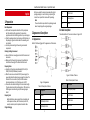
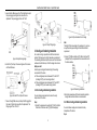
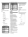
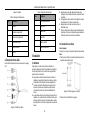
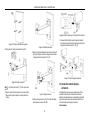
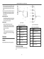
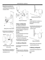
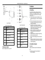
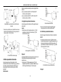
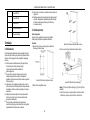
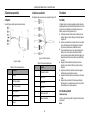
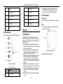
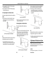
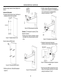
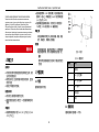
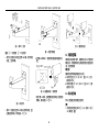
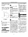
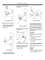
2 Appearance Description
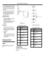
2.1 Appearance
Refer to the following figure for the appearance of the camera.
Figure 2-1 Appearance
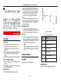
Table 2-1 Description of Device
No.
Description
1
Camera
2
G1/2 Water/Air Outlet
3
G1/2 Water/Air Inlet
4
G1/4 Air Inlet
5
Mounting Base
6
Cables
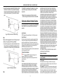
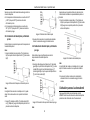
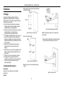
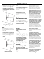
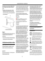
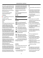
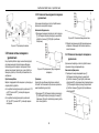
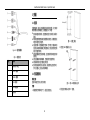
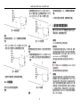
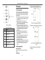
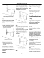
2.2 Cable Description
The cable interfaces of the camera is shown in Figure 2-20.
Figure 2-2 Cables of Camera
Table 2-2 Description of Device
No.
Description
1
Alarm Input/Output
2
RS-232 Cable
3
RS-485 Cable
4
CVBS Cable

Heat Resistant Bullet Camera · Quick Start Guide
2
5
RJ45 Network Cable
6
Power Cable
3 Installation
3.1 Wiring
Please fully take into consideration the installation environment
and position of the device when you plan for the wiring. In order
to make sure the stable power supply and signal transmission,
please closely follow the rules below:
Confirm the installation environment before wiring,
including the wiring distance, wiring environment,
magnetic-field interference, etc.
The rated voltage of the wire should be higher than that the
device requires, so the device can work normally when the
voltage instability occurs.
It’s recommended to use a single complete cable for wiring;
if not, reinforcement measures should be taken to protect
the wiring point between two cables, or the device may
work abnormally due to the circuit aging.
Make sure the device cables are well protected, and take
reinforcement and protective measures during wiring.
Avoid bumping the cables and damaging the magnetic ring,
or the device may work abnormally.
Make sure the cables are not too redundant or stretched too
tight.
The wiring should be completed by professional technicians.
When the device cannot work normally, you can check the
above information for troubleshooting.
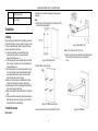
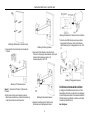
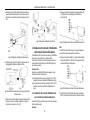
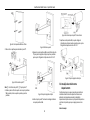
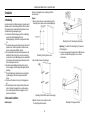
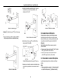
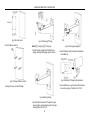
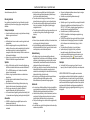
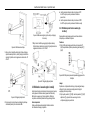
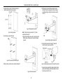
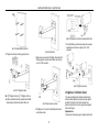
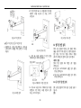
3.2 Install the Camera
Before you start:
The bracket is not included in the package. Please purchase it
separately.
Steps:
1. Drill four holes on the wall according to the dimension of the
wall mounting bracket template.
Figure 3-1 Drill Holes on Wall
2. Drill four M8 screws into the holes.
Figure 3-2 Drill M8 Screws into Holes
3. Loosen and remove the screws to dissemble the PT joint.
Figure 3-3 Dissemble PT Joint
Note: ①: PT Joint Bottom; ②: PT Joint Top
4. Align the four holes on the bracket with the four M8 screws on
the wall, install the bracket on the wall, and tighten the
screws.
Figure 3-4 Install Bracket

Heat Resistant Bullet Camera · Quick Start Guide
3
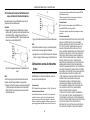
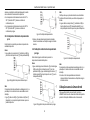
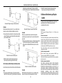
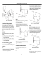
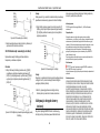
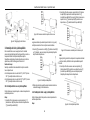
5. Loosen the four M6 screws on the PT joint bottom to adjust
the panning angle, and tighten the screws after the
adjustment. The panning angle is from -45° to 45°.
Figure 3-5 Adjust Panning Angle
6. Install the PT joint top to the mounting base of the camera
with four M6 screws.
Figure 3-6 Install PT Joint Top with Camera
7. Screw in the eight M6 screws, and adjust the tilting angle for
the camera. Tighten the screws after the adjustment. The
tilting range is from -45° to 45°.
Figure 3-7 Adjust Tilting Angle
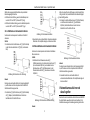
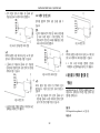
3.3 Cooling and Dedusting Installation
Air or water cooling is required to cool the thermal camera
module if the device works in high-temperature environment.
The dedusting installation helps to remove dust from the device
window and cool the device, so that the image can be clearer.
Before you start:
Select a proper cooling method according to the working
environment of the device.
If the working temperature is between 50 °C and 100 °C
(including 100 °C), select air cooling method.
If the working temperature is between 100 °C and 200 °C
(including 200 °C), select water cooling method.
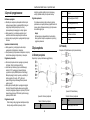
3.3.1 Air Cooling and Dedusting Installation
You can introduce compressed air to reduce the cavity
temperature of the device.
Steps:
1. Connect the compressed air outlet and ① (G1/2 air inlet) at
the bottom of the device with ② (G1/2 screwed pipe).
Figure 3-8 Pipe Connection for Air Cooling
Note:
The length of the screwed pipe in the package is 1 m, and you
can purchase the pipe according to the actual installation
requirement.
2. Connect ③ (G1/2 air outlet) and ④ (G1/4 air inlet) with ⑤
(adapter), then the compressed air can remove the dust on
the device window.
Figure 3-9 Dedusting Installation
3. Wrap the screwed pipe with thermal insulation materials.
Aerogel and aluminum silicate are recommended.
3.3.2 Water Cooling and Dedusting Installation
You can introduce cooling water to reduce the cavity
temperature of the device.
Steps:

Heat Resistant Bullet Camera · Quick Start Guide
4
1. Connect the cooling water outlet and ⑥ (G1/2 water inlet) at
the bottom of the device with ② (one G1/2 screwed pipe),
and connect the backwater inlet and ⑦ (G1/2 water outlet)
on the top of the device with ② (the other G1/2 screwed
pipe).
Figure 3-10 Pipe Connection for Water Cooling
Note:
Make sure the sealing gaskets at the ends of the pipes are well
installed, or the waterproof effect may be affected.
2. Connect the compressed air outlet and ④ (G1/4 air inlet) at
the top of the device with ⑧ (G1/4 screwed pipe), then the
compressed air can remove the dust on the device window.
Figure 3-11 Dedusting Installation
Note:
The length of the screwed pipe in the package is 1 m, and you
can purchase the pipe according to the actual installation
requirement.
3. Wrap the three screwed pipes with thermal insulation
materials. Aerogel and aluminum silicate are recommended.
4 Activate and Access Network Camera
Visit www.hikmicrotech.com to download and install HIKMICRO
Studio. Refer to the user manual of the device for detailed
operation.
Legal Information
© 2022 Hangzhou Microimage Software Co., Ltd. All rights reserved.
About this Manual
The Manual includes instructions for using and managing the Product.
Pictures, charts, images and all other information hereinafter are for
description and explanation only. The information contained in the
Manual is subject to change, without notice, due to firmware updates or
other reasons. Please find the latest version of this Manual at the
HIKMICRO website (www.hikmicrotech.com/).
Please use this Manual with the guidance and assistance of professionals
trained in supporting the Product.
Trademarks Acknowledgement
and other HIKMICRO’s trademarks and logos are the
properties of HIKMICRO in various jurisdictions.
Other trademarks and logos mentioned are the properties of their
respective owners.
Disclaimer
TO THE MAXIMUM EXTENT PERMITTED BY APPLICABLE LAW, THIS
MANUAL AND THE PRODUCT DESCRIBED, WITH ITS HARDWARE,
SOFTWARE AND FIRMWARE, ARE PROVIDED “AS IS” AND “WITH ALL
FAULTS AND ERRORS”. HIKMICRO MAKES NO WARRANTIES, EXPRESS OR
IMPLIED, INCLUDING WITHOUT LIMITATION, MERCHANTABILITY,
SATISFACTORY QUALITY, OR FITNESS FOR A PARTICULAR PURPOSE. THE
USE OF THE PRODUCT BY YOU IS AT YOUR OWN RISK. IN NO EVENT WILL
HIKMICRO BE LIABLE TO YOU FOR ANY SPECIAL, CONSEQUENTIAL,
INCIDENTAL, OR INDIRECT DAMAGES, INCLUDING, AMONG OTHERS,
DAMAGES FOR LOSS OF BUSINESS PROFITS, BUSINESS INTERRUPTION,
OR LOSS OF DATA, CORRUPTION OF SYSTEMS, OR LOSS OF
DOCUMENTATION, WHETHER BASED ON BREACH OF CONTRACT, TORT
(INCLUDING NEGLIGENCE), PRODUCT LIABILITY, OR OTHERWISE, IN
CONNECTION WITH THE USE OF THE PRODUCT, EVEN IF HIKMICRO HAS
BEEN ADVISED OF THE POSSIBILITY OF SUCH DAMAGES OR LOSS.
YOU ACKNOWLEDGE THAT THE NATURE OF THE INTERNET PROVIDES
FOR INHERENT SECURITY RISKS, AND HIKMICRO SHALL NOT TAKE ANY
RESPONSIBILITIES FOR ABNORMAL OPERATION, PRIVACY LEAKAGE OR
OTHER DAMAGES RESULTING FROM CYBER-ATTACK, HACKER ATTACK,
VIRUS INFECTION, OR OTHER INTERNET SECURITY RISKS; HOWEVER,
HIKMICRO WILL PROVIDE TIMELY TECHNICAL SUPPORT IF REQUIRED.
YOU AGREE TO USE THIS PRODUCT IN COMPLIANCE WITH ALL
APPLICABLE LAWS, AND YOU ARE SOLELY RESPONSIBLE FOR ENSURING
THAT YOUR USE CONFORMS TO THE APPLICABLE LAW. ESPECIALLY, YOU
ARE RESPONSIBLE, FOR USING THIS PRODUCT IN A MANNER THAT DOES
NOT INFRINGE ON THE RIGHTS OF THIRD PARTIES, INCLUDING WITHOUT
LIMITATION, RIGHTS OF PUBLICITY, INTELLECTUAL PROPERTY RIGHTS, OR
DATA PROTECTION AND OTHER PRIVACY RIGHTS. YOU SHALL NOT USE
THIS PRODUCT FOR ANY PROHIBITED END-USES, INCLUDING THE
DEVELOPMENT OR PRODUCTION OF WEAPONS OF MASS DESTRUCTION,
THE DEVELOPMENT OR PRODUCTION OF CHEMICAL OR BIOLOGICAL
WEAPONS, ANY ACTIVITIES IN THE CONTEXT RELATED TO ANY NUCLEAR
EXPLOSIVE OR UNSAFE NUCLEAR FUEL-CYCLE, OR IN SUPPORT OF
HUMAN RIGHTS ABUSES.
IN THE EVENT OF ANY CONFLICTS BETWEEN THIS MANUAL AND THE
APPLICABLE LAW, THE LATTER PREVAILS.
Regulatory Information
These clauses apply only to the products bearing the corresponding
mark or information.
FCC Information
Please take attention that changes or modification not expressly
approved by the party responsible for compliance could void the user’s
authority to operate the equipment.
FCC compliance: This equipment has been tested and found to comply
with the limits for Class A device, pursuant to part 15 of the FCC Rules.
These limits are designed to provide reasonable protection against
harmful interference when the equipment is operated in a commercial
environment. This equipment generates, uses, and can radiate radio

Heat Resistant Bullet Camera · Quick Start Guide
5
frequency energy and, if not installed and used in accordance with the
instruction manual, may cause harmful interference to radio
communications. Operation of this equipment in a residential area is
likely to cause harmful interference in which case the user will be
required to correct the interference at his own expense.
FCC Conditions
This device complies with part 15 of the FCC Rules. Operation is subject
to the following two conditions:
1. This device may not cause harmful interference.
2. This device must accept any interference received, including
interference that may cause undesired operation.
EU Conformity Statement
This product and - if applicable - the supplied accessories
too are marked with "CE" and comply therefore with the
applicable harmonized European standards listed under
the EMC Directive 2014/30/EU, the RoHS Directive
2011/65/EU.
2012/19/EU (WEEE directive): Products marked with this
symbol cannot be disposed of as unsorted municipal waste
in the European Union. For proper recycling, return this
product to your local supplier upon the purchase of
equivalent new equipment, or dispose of it at designated
collection points. For more information see: www.recyclethis.info.
2006/66/EC (battery directive): This product contains a
battery that cannot be disposed of as unsorted municipal
waste in the European Union. See the product
documentation for specific battery information. The battery
is marked with this symbol, which may include lettering to
indicate cadmium (Cd), lead (Pb), or mercury (Hg). For proper recycling,
return the battery to your supplier or to a designated collection point.
For more information see: www.recyclethis.info.
Industry Canada ICES-003 Compliance
This device meets the CAN ICES-3 (A)/NMB-3(A) standards requirements.
Safety Instruction
These instructions are intended to ensure that user can use the product
correctly to avoid danger or property loss.
Laws and Regulations
● In the use of the product, you must be in strict compliance with the
electrical safety regulations of the nation and region.
Transportation
● Keep the device in original or similar packaging while transporting it.
● Keep all wrappers after unpacking them for future use. In case of any
failure occurred, you need to return the device to the factory with
the original wrapper. Transportation without the original wrapper
may result in damage on the device and the company shall not take
any responsibilities.
● DO NOT drop the product or subject it to physical shock. Keep the
device away from magnetic interference.
Power Supply
● Please purchase the charger by yourself. Input voltage should meet
the Limited Power Source with 12 VDC according to the IEC62368
standard. Please refer to technical specifications for detailed
information.
● Make sure the plug is properly connected to the power socket.
● The socket-outlet shall be installed near the equipment and shall be
easily accessible.
● DO NOT connect multiple devices to one power adapter, to avoid
over-heating or fire hazards caused by overload.
● DO NOT touch the bare metal contacts of the inlets after the circuit
breaker is turned off. Electricity still exists.
● + identifies the positive terminal(s) of equipment which is used with,
or generates direct current. - identifies the negative terminal(s) of
equipment which is used with, or generates direct current.
Battery
● CAUTION: Risk of explosion if the battery is replaced by an incorrect
type.
● Dispose of used batteries according to the instructions.
● Improper replacement of the battery with an incorrect type may
defeat a safeguard (for example, in the case of some lithium battery
types).
● Do not dispose of the battery into fire or a hot oven, or mechanically
crush or cut the battery, which may result in an explosion.
● Do not leave the battery in an extremely high temperature
surrounding environment, which may result in an explosion or the
leakage of flammable liquid or gas.
● DO NOT subject the battery to extremely low air pressure, which
may result in an explosion or the leakage of flammable liquid or gas.
Installation
● Never place the equipment in an unstable location. The equipment
may fall, causing serious personal injury or death.
● This equipment is for use only with corresponding brackets. Use with
other (carts, stands, or carriers) may result in instability causing
injury.
System Security
● You acknowledge that the nature of Internet provides for inherent
security risks, and our company shall not take any responsibilities for
abnormal operation, privacy leakage or other damages resulting
from cyber attack, hacker attack, however, our company will provide
timely technical support if required.
● Please enforce the protection for the personal information and the
data security as the device may be confronted with the network
security problems when it is connected to the Internet. Please
contact us when the device might exist network security risks.
● Please understand that you have the responsibility to configure all
the passwords and other security settings about the device, and
keep your user name and password.
Maintenance
● If the product does not work properly, please contact your dealer or
the nearest service center. We shall not assume any responsibility
for problems caused by unauthorized repair or maintenance.
● A few device components (e.g., electrolytic capacitor) require regular
replacement. The average lifespan varies, so periodic checking is
recommended. Contact your dealer for details.
● Wipe the device gently with a clean cloth and a small quantity of
ethanol, if necessary.
● If the equipment is used in a manner not specified by the
manufacturer, the protection provided by the device may be
impaired.
● To reduce the risk of fire, replace only with the same type and rating
of fuse.
● The serial port of the equipment is used for debugging only.
Using Environment
● Make sure the running environment meets the requirement of the
device. The operating temperature shall be 0 °C to 200 °C (32 °F to
392 °F), depending on the installation system, and humidity shall be
95% or less.

Heat Resistant Bullet Camera · Quick Start Guide
6
● Place the device in a dry and well-ventilated environment.
● DO NOT expose the device to high electromagnetic radiation or
dusty environments.
● DO NOT aim the lens at the sun or any other bright light.
● The equipment shall not be exposed to dripping or splashing and
that no objects filled with liquids, such as vases, shall be placed on
the equipment.
● No naked flame sources, such as lighted candles, should be placed on
the equipment.
● Provide a surge suppressor at the inlet opening of the equipment
under special conditions such as the mountain top, iron tower, and
forest.
● Burned fingers when handling the parts with symbol . Wait
one-half hour after switching off before handling the parts.
Emergency
● If smoke, odor, or noise arises from the device, immediately turn off
the power, unplug the power cable, and contact the service center.
COMPLIANCE NOTICE: The thermal series products might be subject to
export controls in various countries or regions, including without
limitation, the United States, European Union, United Kingdom and/or
other member countries of the Wassenaar Arrangement. Please consult
your professional legal or compliance expert or local government
authorities for any necessary export license requirements if you intend
to transfer, export, re-export the thermal series products between
different countries.
Deutsch
1 Vorbereitung
Grundlegende Anforderungen
● Beim Betrieb elektronischer Geräte müssen die in Ihrem Land
gültigen elektrischen Sicherheitsvorschriften,
Brandschutzvorschriften und andere entsprechende
Vorschriften unbedingt eingehalten werden.
● Überprüfen Sie den Lieferumfang und vergewissern Sie sich,
dass das Gerät in gutem Zustand ist und alle Teile enthalten
sind.
● Verwenden Sie das System entsprechend den Anforderungen
an die Betriebsumgebung.
Installationsumgebung prüfen
● Stellen Sie sicher, dass ausreichend Platz für die Installation
der Kamera und des Zubehörs vorhanden ist.
● Stellen Sie sicher, dass die Wand stark genug ist, um
mindestens das achtfache Gewicht von Kamera und
Halterung tragen zu können.
Kabel vorbereiten
● Entsprechend der tatsächlichen Netzwerkbandbreite wird
Cat5 (bis 100 m) oder Cat6 (100 m oder mehr) benötigt.
● Wenn die Kamera eine standardmäßige Stromversorgung von
12 V Gleichspannung nutzt, muss das Netzkabel einen
American Wire Gauge von mindestens 18 haben. Die
Gleichung des Querschnitts S (mm²) und des maximalen
Übertragungsabstands L (m) des Blankdrahts ist L = 50 x S.
● Wählen Sie das Videokabel entsprechend der
Übertragungslänge. Das Videokabel muss die
Mindestanforderungen erfüllen: 75 Ω Widerstand; 100 %
leitender Draht mit Kupferkern; 95 % Kupferabschirmgeflecht.
Werkzeuge vorbereiten
Berieten Sie vor der Installation die benötigten Werkzeuge
vor, wie z. B. Dehnschrauben, Elektrohammer, elektrische
Bohrmaschine, Schraubenschlüssel, Schraubendreher,
Spannungsprüfer und Netzwerkkabel.
Originalverpackung
Bitte bewahren Sie nach dem Auspacken der Kamera die
Originalverpackung ordnungsgemäß auf, falls Sie die
Kamera künftig einmal zurücksenden oder zur Reparatur
einschicken müssen. Sie können die Kamera in der
Verpackung verstauen.
Hinweis:
Sie sind für alle Schäden verantwortlich, die beim
Transport mit einer anderen als der Originalverpackung
auftreten.
2 Äußere Beschreibung
2.1 Aufbau
Beachten Sie bezüglich des Aufbaus der Kamera die folgende Abbildung.
Abbildung 2-1 Aufbau
Tabelle 2-1 Beschreibung des Gerätes
Nr.
Beschreibung
1
Kamera
2
G1/2-Wasser-/-Luftauslass
3
G1/2-Wasser-/-Lufteinlass
4
G1/4-Lufteinlass

Heat Resistant Bullet Camera · Quick Start Guide
7
Nr.
Beschreibung
5
Montagefuß
6
Kabel
2.2 Verkabelung
Die Kabelschnittstellen der Kamera werden in Abbildung 2-2
gezeigt0.
Abbildung 2-2 Kabel der Kamera
Tabelle 2-2 Beschreibung des Gerätes
Nr.
Beschreibung
1
Alarmeingang/-ausgang
2
RS-232-Kabel
3
RS-485-Kabel
Nr.
Beschreibung
4
CVBS-Kabel
5
RJ-45-Netzwerkkabel
6
Stromkabel
3 Installation
3.1 Verkabelung
Bei der Planung der Verkabelung müssen Sie die
Installationsumgebung sowie die Position des Gerätes
berücksichtigen. Halten Sie sich zur Gewährleistung einer
stabilen Stromversorgung und Signalübertragung eng an die
nachstehenden Regeln:
Bestätigen Sie die Installationsumgebung vor der
Verkabelung, einschließlich des Kabelabstands, der
Verkabelungsumgebung, Magnetfeldstörungen usw.
Die Nennspannung des Drahtes sollte höher sein als vom
Gerät benötigt, damit das Gerät auch bei instabiler
Spannungsversorgung normal arbeiten kann.
Sie sollten ein einzelnes vollständiges Kabel für die
Verkabelung verwenden. Falls nicht, muss der
Verbindungspunkt zwischen zwei Kabeln verstärkt werden.
Andernfalls funktioniert das Gerät im Laufe der Zeit
möglicherweise nicht mehr richtig.
Achten Sie darauf, dass die Gerätekabel gut geschützt sind.
Ergreifen Sie während der Verkabelung Verstärkungs- und
Schutzmaßnahmen.
Vermeiden Sie Stöße der Kabel und Schäden am Magnetring,
da das Gerät andernfalls möglicherweise nicht richtig
funktioniert.
Achten Sie darauf, dass die Kabel nicht zu redundant sind
oder zu stark gespannt sind.
Die Verkabelung sollte von professionellen Technikern
durchgeführt werden. Prüfen Sie die obigen Informationen
zur Problemlösung, wenn das Gerät nicht normal
funktioniert.
3.2 Kamera installieren
Bevor Sie beginnen:
Die Halterung gehört nicht zum Lieferumfang. Bitte erwerben Sie
es separat.
Schritte:
1. Bohren Sie entsprechend den Abmessungen der Schablone für
die Wandmontagehalterung vier Löcher in die Wand.
Abbildung 3-1 Löcher in die Wand bohren
2. Drehen Sie vier M8-Schrauben in die Löcher.

Heat Resistant Bullet Camera · Quick Start Guide
8
Abbildung 3-2 M8-Schrauben in die Löcher drehen
3. Lösen und entfernen Sie die Schrauben zur Demontage des
PT-Gelenks.
Abbildung 3-3 PT-Gelenk demontieren
Hinweis: ①: Unterseite des PT-Gelenks; ②: Oberseite des
PT-Gelenks
4. Richten Sie die vier Löcher an der Halterung an den vier
M8-Schrauben an der Wand aus, installieren Sie die Halterung
an der Wand und ziehen Sie die Schrauben fest.
Abbildung 3-4 Halterung installieren
5. Lösen Sie die vier M6-Schrauben an der Unterseite des
PT-Gelenks zur Anpassung des Schwenkwinkels. Ziehen Sie die
Schrauben nach der Anpassung wieder an. Der
Schwenkwinkel geht von -45° bis 45°.
Abbildung 3-5 Schwenkwinkel anpassen
6. Installieren Sie die Oberseite des PT-Gelenks mit vier
M6-Schrauben an der Montagebasis der Kamera.
Abbildung 3-6 Oberseite des PT-Gelenks mit Kamera installieren
7. Drehen Sie die acht M6-Schrauben ein und passen Sie den
Neigungswinkel der Kamera an. Ziehen Sie die Schrauben
nach der Anpassung fest. Der Neigungsbereich ist von -45° bis
45°.
Abbildung 3-7 Neigungswinkel anpassen
3.3 Kühlende und entstaubende Installation
Zur Kühlung des Wärmebildkameramoduls ist eine Luft- oder
Wasserkühlung erforderlich, wenn das Gerät in einer Umgebung
mit hohen Temperaturen arbeitet. Die entstaubende Installation
hilft dabei, Staub vom Gerätefenster zu entfernen und das Gerät
zu kühlen, damit das Bild klarer ist.
Bevor Sie beginnen:

Heat Resistant Bullet Camera · Quick Start Guide
9
Wählen Sie eine geeignete Kühlmethode entsprechend der
Betriebsumgebung des Gerätes.
Wählen Sie die Luftkühlung, wenn die Betriebstemperatur
zwischen 50 °C und 100 °C (inklusive 100 °C) liegt.
Wählen Sie die Wasserkühlung, wenn die Betriebstemperatur
zwischen 100 °C und 200 °C (inklusive 200 °C) liegt.
3.3.1 Luftkühlende und entstaubende Installation
Sie können die Innentemperatur des Gerätes mit Druckluft
reduzieren.
Schritte:
1. Verbinden Sie den Druckluftauslass und ① (G1/2-Lufteinlass)
an der Unterseite des Gerätes mit ② (G1/2, verschraubtes
Rohr).
Abbildung 3-8 Rohranschluss für Luftkühlung
Hinweis:
Die Länge des verschraubten Rohrs in der Verpackung beträgt 1
m, und Sie können ein Rohr entsprechend der tatsächlichen
Installationsanforderung erwerben.
2. Verbinden Sie ③ (G1/2-Lufteinlass) und ④ (G1/4-Lufteinlass)
mit ⑤ (Adapter). Anschließend können Sie Staub am
Gerätefenster mit Druckluft entfernen.
Abbildung 3-9 Entstaubende Installation
3. Umwickeln Sie das verschraubte Rohr mit wärmeisolierenden
Materialien. Wir empfehlen Aerogel und Aluminium-Silikat.
3.3.2 Wasserkühlende und entstaubende Installation
Sie können die Innentemperatur des Gerätes mit kühlendem
Wasser reduzieren.
Schritte:
1. Verbinden Sie den Kühlwasserauslass und ⑥
(G1/2-Wassereinlass) an der Unterseite des Gerätes mit ②
(ein verschraubtes G1/2-Rohr), und verbinden Sie den
Rückstaueinlass und ⑦ (G1/2-Wasserauslass) an der
Oberseite des Gerätes mit ② (das andere verschraubte
G1/2-Rohr).
Abbildung 3-10 Rohranschluss für Wasserkühlung
Hinweis:
Achten Sie darauf, dass die Dichtungen an den Enden der Rohre
richtig installiert sind; andernfalls könnte die Wasserdichtigkeit
beeinträchtigt werden.
2. Verbinden Sie den Druckluftauslass und ④ (G1/4-Lufteinlass)
an der Oberseite des Gerätes mit ⑧ (verschraubtes
G1/4-Rohr). Anschließend können Sie den Staub am
Gerätefenster mit Druckluft entfernen.
Abbildung 3-11 Entstaubende Installation
Hinweis:
Die Länge des verschraubten Rohrs in der Verpackung beträgt 1
m, und Sie können ein Rohr entsprechend der tatsächlichen
Installationsanforderung erwerben.
3. Umwickeln Sie die drei verschraubten Rohre mit
wärmeisolierenden Materialien. Wir empfehlen Aerogel und
Aluminium-Silikat.
4 Netzwerkkamera aktivieren und
darauf zugreifen
Besuchen Sie zum Herunterladen und Installieren von HIKMICRO
Studio die Website www.hikmicrotech.com. Beachten Sie für
detaillierte Anweisungen die Bedienungsanleitung des Gerätes.

Heat Resistant Bullet Camera · Quick Start Guide
10
Rechtliche Informationen
© 2022 Hangzhou Microimage Software Co., Ltd. Alle Rechte
vorbehalten.
Hinweise zu dieser Bedienungsanleitung
Die Bedienungsanleitung enthält Anleitungen zur Verwendung und
Verwaltung des Produkts. Bilder, Diagramme, Abbildungen und alle
sonstigen Informationen dienen nur der Beschreibung und Erklärung. Die
Änderung der in der Bedienungsanleitung enthaltenen Informationen ist
aufgrund von Firmware-Aktualisierungen oder aus anderen Gründen
vorbehalten. Die neueste Version dieses Handbuchs finden Sie auf der
HIKMICRO-Website (www.hikmicrotech.com/).
Bitte verwenden Sie diese Bedienungsanleitung unter Anleitung und
Unterstützung von Fachleuten, die für den Support des Produkts geschult
sind.
Marken
und andere Marken und Logos von HIKMICRO sind Eigentum
von HIKMICRO in verschiedenen Gerichtsbarkeiten.
Andere hier erwähnte Marken und Logos sind Eigentum ihrer jeweiligen
Inhaber.
Haftungsausschluss
DIESE BEDIENUNGSANLEITUNG UND DAS BESCHRIEBENE PRODUKT MIT
SEINER HARDWARE, SOFTWARE UND FIRMWARE WERDEN, SOWEIT
GESETZLICH ZULÄSSIG, IN DER „VORLIEGENDEN FORM“ UND MIT „ALLEN
FEHLERN UND IRRTÜMERN“ BEREITGESTELLT. HIKMICRO GIBT KEINE
GARANTIEN, WEDER AUSDRÜ CKLICH NOCH STILLSCHWEIGEND,
EINSCHLIEßLICH, ABER NICHT DARAUF BESCHRÄNKT, MARKTGÄNGIGKEIT,
ZUFRIEDENSTELLENDE QUALITÄT ODER EIGNUNG FÜR EINEN
BESTIMMTEN ZWECK. DIE NUTZUNG DES PRODUKTS DURCH SIE
ERFOLGT AUF IHRE EIGENE GEFAHR. IN KEINEM FALL IST HIKMICRO
IHNEN GEGENÜBER HAFTBAR FÜR BESONDERE, ZUFÄLLIGE, DIREKTE
ODER INDIREKTE SCHÄDEN, EINSCHLIEßLICH, JEDOCH NICHT DARAUF
BESCHRÄNKT, VERLUST VON GESCHÄFTSGEWINNEN,
GESCHÄFTSUNTERBRECHUNG, DATENVERLUST, SYSTEMBESCHÄDIGUNG,
VERLUST VON DOKUMENTATIONEN, SEI ES AUFGRUND VON
VERTRAGSBRUCH, UNERLAUBTER HANDLUNG (EINSCHLIEßLICH
FAHRLÄSSIGKEIT), PRODUKTHAFTUNG ODER ANDERWEITIG, IN
VERBINDUNG MIT DER VERWENDUNG DIESES PRODUKTS, SELBST WENN
HIKMICRO ÜBER DIE MÖGLICHKEIT DERARTIGER SCHÄDEN ODER
VERLUSTE INFORMIERT WAR.
SIE ERKENNEN AN, DASS DIE NATUR DES INTERNETS DAMIT
VERBUNDENE SICHERHEITSRISIKEN BEINHALTET. HIKMICRO ÜBERNIMMT
KEINE VERANTWORTUNG FÜ R ANORMALEN BETRIEB, DATENVERLUST
ODER ANDERE SCHÄDEN, DIE SICH AUS CYBERANGRIFFEN,
HACKERANGRIFFEN, VIRUSINFEKTION ODER ANDEREN
SICHERHEITSRISIKEN IM INTERNET ERGEBEN. HIKMICRO WIRD JEDOCH
BEI BEDARF ZEITNAH TECHNISCHEN SUPPORT LEISTEN.
SIE STIMMEN ZU, DIESES PRODUKT IN ÜBEREINSTIMMUNG MIT ALLEN
GELTENDEN GESETZEN ZU VERWENDEN, UND SIE SIND ALLEIN DAFÜR
VERANTWORTLICH, DASS IHRE VERWENDUNG GEGEN KEINE GELTENDEN
GESETZE VERSTÖ ßT. INSBESONDERE SIND SIE DAFÜR VERANTWORTLICH,
DIESES PRODUKT SO ZU VERWENDEN, DASS DIE RECHTE DRITTER NICHT
VERLETZT WERDEN, EINSCHLIEßLICH, ABER NICHT BESCHRÄNKT AUF
VERÖ FFENTLICHUNGSRECHTE, DIE RECHTE AN GEISTIGEM EIGENTUM
ODER DEN DATENSCHUTZ UND ANDERE PERSÖ NLICHKEITSRECHTE. SIE
DÜRFEN DIESES PRODUKT NICHT FÜR VERBOTENE ENDANWENDUNGEN
VERWENDEN, EINSCHLIESSLICH DER ENTWICKLUNG ODER HERSTELLUNG
VON MASSENVERNICHTUNGSWAFFEN, DER ENTWICKLUNG ODER
HERSTELLUNG CHEMISCHER ODER BIOLOGISCHER WAFFEN, JEGLICHER
AKTIVITÄTEN IM ZUSAMMENHANG MIT EINEM NUKLEAREN
SPRENGKÖ RPER ODER UNSICHEREN NUKLEAREN
BRENNSTOFFKREISLAUF BZW. ZUR UNTERSTÜTZUNG VON
MENSCHENRECHTSVERLETZUNGEN.
IM FALL VON WIDERSPRÜ CHEN ZWISCHEN DIESER
BEDIENUNGSANLEITUNG UND GELTENDEM RECHT IST LETZTERES
MASSGEBLICH.
Behördliche Informationen
Diese Bestimmungen gelten nur für Produkte, die das entsprechende
Zeichen oder die entsprechenden Informationen tragen.
EU-Konformitätserklärung
Dieses Produkt und – gegebenenfalls – das mitgelieferte
Zubehör sind mit dem „CE“-Zeichen gekennzeichnet und
erfüllen daher die gültigen harmonisierten Europäischen
Normen, die in der EMV-Richtlinie 2014/30/EG und der
RoHS-Richtlinie 2011/65/EU aufgelistet sind.
2012/19/EU (Elektroaltgeräte-Richtlinie): Produkte, die mit
diesem Symbol gekennzeichnet sind, dürfen innerhalb der
Europäischen Union nicht mit dem Hausmüll entsorgt
werden. Für korrektes Recycling geben Sie dieses Produkt an
Ihren örtlichen Fachhändler zurück oder entsorgen Sie es an
einer der Sammelstellen. Weitere Informationen finden Sie unter:
www.recyclethis.info
2006/66/EC (Batterierichtlinie): Dieses Produkt enthält eine
Batterie, die innerhalb der Europäischen Union nicht mit
dem Hausmüll entsorgt werden darf. Siehe
Produktdokumentation für spezifische Hinweise zu
Batterien. Die Batterie ist mit diesem Symbol
gekennzeichnet, das zusätzlich die Buchstaben Cd für Cadmium, Pb für
Blei oder Hg für Quecksilber enthalten kann. Für korrektes Recycling
geben Sie die Batterie an Ihren örtlichen Fachhändler zurück oder
entsorgen Sie sie an einer der Sammelstellen. Für weitere Informationen
siehe: www.recyclethis.info.
Sicherheitshinweis
Diese Anleitungen sollen gewährleisten, dass Sie das Produkt korrekt
verwenden, um Gefahren oder Sachschäden zu vermeiden.
Gesetze und Vorschriften
● Bei der Verwendung des Produkts müssen die elektrischen
Sicherheitsbestimmungen des Landes oder der Region strikt
eingehalten werden.
Transportwesen
● Bewahren Sie das Gerät beim Transport in der ursprünglichen oder
einer vergleichbaren Verpackung auf.
● Bewahren Sie das gesamte Verpackungsmaterial nach dem
Auspacken für zukünftigen Gebrauch auf. Im Falle eines Fehlers
müssen Sie das Gerät in der Originalverpackung an das Werk
zurücksenden. Beim Transport ohne Originalverpackung kann das
Gerät beschädigt werden und wir übernehmen keine Verantwortung.
● Lassen Sie das Produkt nicht fallen und vermeiden Sie heftige Stöße.
Halten Sie das Gerät von magnetischen Störungen fern.
Spannungsversorgung
● Erwerben Sie das Ladegerät selbst. Die Eingangsspannung muss einer
Stromquelle mit begrenzter Leistung mit 12 V Gleichspannung gemäß
der Norm IEC 62368 entsprechen. Siehe technische Daten für
detaillierte Informationen.
● Stellen Sie sicher, dass der Stecker richtig in der Steckdose steckt.
● Die Steckdose sollte sich in der Nähe des Geräts befinden und muss

Heat Resistant Bullet Camera · Quick Start Guide
11
einfach zugänglich sein.
● Verbinden Sie NICHT mehrere Geräte mit einem Netzteil, da es
andernfalls durch Ü berlastung zu einer Überhitzung oder einem
Brand kommen kann.
● Berühren Sie NICHT die blanken Metallkontakte der Eingänge,
nachdem der Schutzschalter ausgeschaltet wurde. Sie stehen noch
unter Strom.
● + kennzeichnet den/die Pluspol(e) von Geräten, die mit Gleichstrom
betrieben werden oder Gleichstrom erzeugen. – kennzeichnet
den/die Minuspol(e) von Geräten, die mit Gleichstrom betrieben
werden oder Gleichstrom erzeugen.
Batterie
● ACHTUNG: Bei Austausch der Batterie durch einen falschen Typ
besteht Explosionsgefahr.
● Entsorgen Sie verbrauchte Batterien entsprechend der Anleitung.
● Unsachgemäßer Austausch der Batterien durch einen falschen Typ
kann eine Schutzvorrichtung umgehen (z. B. bei einigen
Lithium-Batterietypen).
● Batterien nicht durch Verbrennen, in einem heißen Ofen oder
Zerkleinern oder Zerschneiden entsorgen. Das kann zu einer
Explosion führen.
● Bewahren Sie Batterien nicht in einer Umgebung mit extrem hoher
Temperatur auf. Das kann zu einer Explosion oder zum Auslaufen von
entflammbarer Flüssigkeit oder Gas führen.
● Setzen Sie Batterien keinem extrem niedrigen Luftdruck aus. Das
kann zu einer Explosion oder zum Auslaufen von entflammbarer
Flüssigkeit oder Gas führen.
Installation
● Stellen Sie das Gerät niemals an einem instabilen Ort auf. Es könnte
umfallen und schwere oder sogar tödliche Verletzungen verursachen.
● Dieses Gerät darf nur mit den entsprechenden Halterungen
verwendet werden. Die Verwendung anderen Halterungen (Wagen,
Ständer oder Träger) kann zu Instabilität führen und Verletzungen
verursachen.
Systemsicherheit
● Sie erkennen an, dass die Natur des Internets damit verbundene
Sicherheitsrisiken mit sich bringt und unser Unternehmen übernimmt
keine Verantwortung für anormale Betriebsabläufe,
Datenschutzverletzungen oder andere Schäden, die sich durch Cyber-
oder Hackerangriffe ergeben. Bei Bedarf wird unser Unternehmen
jedoch zeitnahe technische Unterstützung leisten.
● Bitte sorgen Sie für den Schutz der persönlichen Daten und die
Datensicherheit, da das Gerät Netzwerksicherheitsproblemen
ausgesetzt werden kann, wenn es mit dem Internet verbunden ist.
Bitte setzen Sie sich mit uns in Verbindung, wenn das Gerät
Netzwerksicherheitsrisiken aufweist.
● Bitte nehmen Sie zur Kenntnis, dass Sie die Verantwortung dafür
tragen, alle Passwörter und andere Sicherheitseinstellungen für das
Gerät zu konfigurieren und Ihren Benutzernamen und Ihr Passwort
aufzubewahren.
Wartung
● Falls das Produkt nicht einwandfrei funktionieren sollte, wenden Sie
sich an Ihren Händler oder den nächstgelegenen Kundendienst. Wir
übernehmen keine Haftung für Probleme, die durch nicht Reparatur-
oder Instandhaltungsarbeiten von nicht autorisierten Dritten
verursacht werden.
● Einige Gerätekomponenten (z. B. Elektrolytkondensator) müssen
regelmäßig ausgetauscht werden. Die durchschnittliche Lebensdauer
variiert, weshalb eine regelmäßige Prüfung empfohlen wird.
Einzelheiten erfahren Sie von Ihrem Händler.
● Wischen Sie das Gerät bei Bedarf sanft mit einem sauberen Tuch und
einer geringen Menge Ethanol ab.
● Wenn das Gerät nicht vom Hersteller vorgegebenem Sinne genutzt
wird, kann der durch das Gerät bereitgestellte Schutz beeinträchtigt
werden.
● Um die Feuergefahr zu verringern, ersetzen Sie Sicherungen nur
durch Sicherungen des gleichen Typs und der gleichen Leistung.
● Die serielle Schnittstelle des Geräts wird nur zur Fehlersuche
verwendet.
Einsatzumgebung
● Achten Sie darauf, dass die Betriebsumgebung den Anforderungen
des Geräts entspricht. Die Betriebstemperatur muss je nach
Installationssystem zwischen 0 und 200 °C (32 bis 392 °F) liegen, und
die Feuchtigkeit darf maximal 95 % betragen.
● Stellen Sie das Gerät an einem kühlen und gut belüfteten Ort auf.
● Setzen Sie das Gerät KEINER hohen elektromagnetischen Strahlung
oder staubigen Umgebungen aus.
● Richten Sie das Objektiv NICHT auf die Sonne oder eine andere helle
Lichtquelle.
● Das Gerät vor tropfenden oder spritzenden Flüssigkeiten schützen.
Auf dem Gerät dürfen keine mit Flüssigkeit gefüllten Objekte, wie z. B.
Vasen, abgestellt werden.
● Stellen Sie keine offenen Flammen (wie brennende Kerzen) auf dem
Gerät ab.
● Sorgen Sie für einen Ü berspannungsschutz an der Eingängen der
Anlage bei besonderen Umgebungsbedingungen wie Berggipfel,
Metallturm und Wald.
● Dieses Symbol weist darauf hin, dass Sie sich beim Umgang mit
den Teilen die Finger verbrennen können. Warten Sie nach dem
Ausschalten eine halbe Stunde, bevor Sie die Teile anfassen.
Notruf
● Sollten sich Rauch, Gerüche oder Geräusche in dem Gerät entwickeln,
so schalten Sie es unverzüglich aus und ziehen Sie den Netzstecker;
wenden Sie sich dann an den Kundendienst.
RECHTLICHER HINWEIS: Die Produkte der Wärmebild-Serie unterliegen
unter Umständen in verschiedenen Ländern oder Regionen
Exportkontrollen, wie zum Beispiel in den Vereinigten Staaten, der
Europäischen Union, dem Vereinigten Königreich und/oder anderen
Mitgliedsländern des Wassenaar-Abkommens. Bitte wenden Sie sich an
Ihren professionellen Rechts- oder Compliance-Experten oder an die
zuständigen Behörden, wenn Sie beabsichtigen, Produkte der
Wärmebild-Serie zwischen verschiedenen Ländern zu transferieren, zu
exportieren oder zu reexportieren, um Informationen über eine
eventuell erforderliche Ausfuhrgenehmigung zu erhalten.
Français
1 Préparation
Configuration requise de base
● L’ensemble du fonctionnement électronique doit être en
conformité absolue avec les règles de sécurité en matière
d’installation électrique, de prévention des risques d’incendie
et toutes autres règlementations connexes applicables dans
votre région.
● Vérifiez le contenu de l’emballage et assurez-vous que
l’appareil est en bon état et que toutes les pièces

Heat Resistant Bullet Camera · Quick Start Guide
12
d’assemblage sont incluses.
● Utilisez le système conformément aux exigences relatives à
l’environnement de travail.
Vérification de l’environnement d’installation
● Assurez-vous qu’il y a suffisamment de place pour installer la
caméra et les accessoires.
● Assurez-vous que le mur est suffisamment solide pour
supporter au moins huit fois le poids de la caméra et de son
support.
Préparation des câbles
● Selon la bande passante réelle du réseau, le Cat5 (de 100 M)
ou le Cat6 (supérieur à 100 M) est nécessaire.
● Lorsque la caméra utilise une alimentation électrique
standard de 12 V CC, le câble d’alimentation doit être un
câble de 18 AWG (American Wire Gauge) ou supérieur. La
formule de la section S (mm²) et de la distance de
transmission maximale L (m) du fil nu est L = 50 x S.
● Choisissez le câble vidéo selon la longueur de transmission.
La vidéo doit répondre aux exigences minimales suivantes :
résistance de 75 Ω ; fil conducteur d’âme entièrement en
cuivre ; blindage en cuivre à 95 % de tissage.
Préparation des outils
Avant l’installation, veuillez préparer les outils nécessaires,
tels que les vis à expansion, le marteau électrique, la
perceuse électrique, la clé, le tournevis, la sonde
électrique et le câble réseau.
Emballage d’origine
Lorsque vous déballez l’appareil, veuillez conserver
correctement l’emballage d’origine, au cas où vous
retourneriez ou répareriez l’appareil. Vous pouvez
emballer la caméra avec l’emballage.
Remarque :
L’utilisateur est responsable de tout dommage causé lors
du transport avec un emballage non original.
2 Description de l’apparence
2.1 Apparence
Reportez-vous à la figure suivante pour l’apparence de la
caméra.
Figure 2-1 Apparence
Tableau 2-1 Description de l’appareil
N°
Description
1
Caméra
2
Sortie d’air/eau G1/2
3
Admission d’air/eau G1/2
4
Admission d’air G1/4
5
Base de montage
6
Câbles
2.2 Descriptions des câbles
Les interfaces des câbles de la caméra sont illustrées à la
figure 2-20.
Figure 2-2 Câbles de la caméra
Tableau 2-2 Description de l’appareil
N°
Description
1
Entrée/sortie alarme
2
Câble RS-232
3
Câble RS-485
4
Câble CVBS
5
Câble réseau RJ45
6
Câble d’alimentation

Heat Resistant Bullet Camera · Quick Start Guide
13
3 Installation
3.1 Câblage
Veuillez prendre en considération l’environnement d’installation
et la position de l’appareil lorsque vous planifiez le câblage. Afin
de garantir la stabilité de l’alimentation électrique et de la
transmission du signal, veuillez suivre attentivement les règles
ci-dessous :
confirmez l’environnement d’installation avant le câblage, y
compris la distance de câblage, l’environnement de câblage,
l’interférence du champ magnétique, etc. ;
la tension nominale du câble doit être supérieure à celle
requise par l’appareil, afin que l’appareil puisse fonctionner
normalement en cas d’instabilité de la tension ;
il est recommandé d’utiliser un seul câble complet pour le
câblage ; sinon, des mesures de renforcement doivent être
prises pour protéger le point de câblage entre deux câbles,
ou l’appareil pourrait fonctionner anormalement en raison
du vieillissement du circuit ;
assurez-vous que les câbles de l’appareil sont bien protégés
et prenez des mesures de renforcement et de protection lors
du câblage ;
évitez de heurter les câbles et d’endommager l’anneau
magnétique, sinon l’appareil risque de fonctionner
anormalement ;
assurez-vous que les câbles ne sont pas trop redondants ou
trop tendus ;
le câblage doit être effectué par des techniciens
professionnels. Lorsque l’appareil ne peut pas fonctionner
normalement, vous pouvez vérifier les informations
ci-dessus pour le dépannage.
3.2 Installation de la caméra
Avant de commencer :
Le support n’est pas inclus dans l’emballage. Il doit être acheté
séparément.
Procédures :
1. Percez quatre trous dans le mur selon les dimensions du
gabarit du support de fixation murale.
Figure 3-1 Perçage des trous sur le mur
2. Percez quatre vis M8 dans les trous.
Figure 3-2 Perçage des vis M8 dans les trous
3. Desserrez les vis et retirez-les pour démonter le joint PT.
Figure 3-3 Démontage du joint PT
Remarque : ① : Bas du joint PT ; ② : Haut du joint PT
4. Alignez les quatre trous du support sur les quatre vis M8 du
mur, puis installez le support sur le mur et serrez les vis.
Figure 3-4 Installation du support

Heat Resistant Bullet Camera · Quick Start Guide
14
5. Desserrez les quatre vis M6 au bas du joint PT pour régler
l’angle de panoramique et serrez les vis après le réglage.
L’angle de panoramique est compris entre -45° et 45°.
Figure 3-5 Réglage de l’angle de panoramique
6. Installez le haut du joint PT sur la base de montage de la
caméra à l’aide de quatre vis M6.
Figure 3-6 Installation du haut du joint PT sur la caméra
7. Serrez les huit vis M6 et réglez l’angle d’inclinaison de la
caméra. Serrez les vis après le réglage. La plage d’inclinaison
est comprise entre -45° et 45°.
Figure 3-7 Réglage de l’ange d’inclinaison
3.3 Installation du système de refroidissement
et de dépoussiérage
Un système de refroidissement par air ou par eau est nécessaire
pour refroidir le module de caméra thermique si l’appareil
fonctionne dans un environnement à haute température.
L’installation du système de dépoussiérage permet d’éliminer la
poussière de la fenêtre de l’appareil et de refroidir l’appareil, afin
que l’image soit plus nette.
Avant de commencer :
Sélectionnez une méthode de refroidissement appropriée selon
l’environnement de fonctionnement de l’appareil.
Si la température de fonctionnement est comprise entre
50 °C et 100 °C (100 °C inclus), sélectionnez la méthode de
refroidissement par air.
Si la température de fonctionnement est comprise entre
100 °C et 200 °C (200 °C inclus), sélectionnez la méthode de
refroidissement par eau.
3.3.1 Installation du système de refroidissement par
air et de dépoussiérage
Vous pouvez introduire de l’air comprimé pour réduire la
température de la cavité de l’appareil.
Procédures :
1. Raccordez la sortie d’air comprimé et ① (l’entrée d’air G1/2)
au bas de l’appareil avec ② (le tuyau vissé G1/2).
Figure 3-8 Raccordement du tuyau pour le refroidissement par
air
Remarque :
La longueur du tuyau vissé dans l’emballage est de 1 m. Vous
pouvez également acheter le tuyau selon les exigences réelles de
l’installation.
2. Raccordez ③ (la sortie d’air G1/2) et ④ (l’admission d’air G1/4)
avec ⑤ (l’adaptateur) pour que l’air comprimé puisse enlever
la poussière sur la fenêtre de l’appareil.

Heat Resistant Bullet Camera · Quick Start Guide
15
Figure 3-9 Installation du système de dépoussiérage
3. Enveloppez le tuyau vissé avec des matériaux d’isolation
thermique. L’aérogel et le silicate d’aluminium sont
recommandés.
3.3.2 Installation du système de refroidissement par
eau et de dépoussiérage
Vous pouvez introduire de l’eau de refroidissement pour réduire
la température de la cavité de l’appareil.
Procédures :
1. Raccordez la sortie d’eau de refroidissement et ⑥ (l’entrée
d’eau G1/2) au bas de l’appareil avec ② (un tuyau vissé G1/2),
et raccordez l’entrée d’eau de reflux et ⑦ (la sortie d’eau G1/2)
au-dessus de l’appareil avec ② (l’autre tuyau vissé G1/2).
Figure 3-10 Raccordement du tuyau pour le refroidissement par
eau
Remarque :
Assurez-vous que les joints d’étanchéité aux extrémités des
tuyaux sont correctement installés, sinon l’effet d’étanchéité
peut être affecté.
2. Connectez la sortie d’air comprimé et ④ (l’admission d’air
G1/4) au-dessus de l’appareil avec ⑧ (le tuyau vissé G1/4)
pour que l’air comprimé puisse enlever la poussière sur la
fenêtre de l’appareil.
Figure 3-11 Installation du système de dépoussiérage
Remarque :
La longueur du tuyau vissé dans l’emballage est de 1 m. Vous
pouvez également acheter le tuyau selon les exigences réelles de
l’installation.
3. Enveloppez les trois tuyaux vissés avec des matériaux
d’isolation thermique. L’aérogel et le silicate d’aluminium sont
recommandés.
4 Activation et accès à la caméra réseau
Visitez www.hikmicrotech.com pour télécharger et installer
HIKMICRO Studio. Reportez-vous au manuel d’utilisation de
l’appareil pour un fonctionnement détaillé.
Informations légales
© 2022 Hangzhou Microimage Software Co., Ltd. Tous droits réservés.
À propos de ce manuel
Ce manuel fournit des instructions d’utilisation et de gestion du produit.
Les images, les tableaux, les figures et toutes les autres informations
ci-après ne sont donnés qu’à titre de description et d’explication. Les
informations contenues dans ce manuel sont modifiables sans préavis,
en raison d’une mise à jour d’un micrologiciel ou pour d’autres raisons.
Veuillez trouver la dernière version de ce manuel sur le site Internet de
HIKMICRO (www.hikmicrotech.com).
Veuillez utiliser ce mode d’emploi avec les conseils et l’assistance de
professionnels spécialement formés dans la prise en charge de ce
produit.
Reconnaissance des marques de commerce
Et les autres marques commerciales et logos de HIKMICRO
sont la propriété de HIKMICRO dans diverses juridictions.
Toutes les autres marques et tous les logos mentionnés appartiennent à
leurs propriétaires respectifs.
Clause d’exclusion de responsabilité
DANS LES LIMITES AUTORISÉES PAR LA LOI EN VIGUEUR, LE PRÉSENT
MANUEL ET LE PRODUIT DÉCRIT, AINSI QUE SON MATÉRIEL, SES
LOGICIELS ET SES MICROLOGICIELS, SONT FOURNIS « EN L’ÉTAT » ET
« AVEC CES FAIBLESSES ET ERREURS ». HIKMICRO NE FAIT AUCUNE
GARANTIE, EXPLICITE OU IMPLICITE, Y COMPRIS, MAIS SANS S’Y LIMITER,
DE QUALITÉ MARCHANDE, DE QUALITÉ SATISFAISANTE, OU
D’ADÉQUATION À UN USAGE PARTICULIER. VOUS UTILISEZ LE PRODUIT À
VOS PROPRES RISQUES. EN AUCUN CAS, HIKMICRO NE SERA TENU
RESPONSABLE DE TOUT DOMMAGE SPÉCIAL, CONSÉCUTIF, ACCESSOIRE
OU INDIRECT, Y COMPRIS, ENTRE AUTRES, LES DOMMAGES RELATIFS À
LA PERTE DE PROFITS D’ENTREPRISE, À L’INTERRUPTION D’ACTIVITÉS
COMMERCIALES, OU LA PERTE DES DONNÉES, LA CORRUPTION DES
SYSTÈMES, OU LA PERTE DES DOCUMENTS, S’ILS SONT BASÉS SUR UNE
VIOLATION DE CONTRAT, UNE FAUTE (Y COMPRIS LA NÉGLIGENCE), LA
RESPONSABILITÉ EN MATIÈRE DE PRODUITS, OU AUTRE, EN RAPPORT
AVEC L’UTILISATION DU PRODUIT, MÊME SI HIKMICRO A ÉTÉ INFORMÉ
DE LA POSSIBILITÉ D’UN TEL DOMMAGE OU D’UNE TELLE PERTE.
VOUS RECONNAISSEZ QUE LA NATURE D’INTERNET EST SOURCE DE
RISQUES DE SÉCURITÉ INHÉRENTS, ET HIKMICRO SE DÉGAGE DE TOUTE
RESPONSABILITÉ EN CAS DE FONCTIONNEMENT ANORMAL,
DIVULGATION D’INFORMATIONS CONFIDENTIELLES OU AUTRES
DOMMAGES DÉCOULANT D’UNE CYBERATTAQUE, D’UN PIRATAGE
INFORMATIQUE, D’UNE INFECTION PAR DES VIRUS, OU AUTRES RISQUES
DE SÉCURITÉ LIÉS À INTERNET ; TOUTEFOIS, HIKMICRO FOURNIRA UNE
ASSISTANCE TECHNIQUE DANS LES DÉLAIS SI NÉCESSAIRE.
VOUS ACCEPTEZ D’UTILISER CE PRODUIT CONFORMÉMENT À
L’ENSEMBLE DES LOIS EN VIGUEUR. IL EST DE VOTRE RESPONSABILITÉ
EXCLUSIVE DE VEILLER À CE QUE VOTRE UTILISATION SOIT CONFORME À
LA LOI APPLICABLE. IL VOUS APPARTIENT SURTOUT D’UTILISER CE
PRODUIT D’UNE MANIÈRE QUI NE PORTE PAS ATTEINTE AUX DROITS DE

Heat Resistant Bullet Camera · Quick Start Guide
16
TIERS, Y COMPRIS, MAIS SANS S’Y LIMITER, LES DROITS DE PUBLICITÉ,
LES DROITS DE PROPRIÉTÉ INTELLECTUELLE, OU LA PROTECTION DES
DONNÉES ET D’AUTRES DROITS À LA VIE PRIVÉE. VOUS NE DEVEZ PAS
UTILISER CE PRODUIT POUR TOUTE UTILISATION FINALE INTERDITE,
NOTAMMENT LA MISE AU POINT OU LA PRODUCTION D’ARMES DE
DESTRUCTION MASSIVE, LA MISE AU POINT OU LA FABRICATION
D’ARMES CHIMIQUES OU BIOLOGIQUES, LES ACTIVITÉS DANS LE
CONTEXTE LIÉ AUX EXPLOSIFS NUCLÉAIRES OU AU CYCLE DU
COMBUSTIBLE NUCLÉAIRE DANGEREUX, OU SOUTENANT LES
VIOLATIONS DES DROITS DE L’HOMME.
EN CAS DE CONFLIT ENTRE CE MANUEL ET LES LOIS EN VIGUEUR, CES
DERNIÈRES PRÉVALENT.
Réglementation
Ces clauses ne s’appliquent qu’aux produits portant la marque ou
l’information correspondante.
Déclaration de conformité UE
Le présent produit et, le cas échéant, les accessoires
fournis, portent la mention « CE » et sont par conséquent
conformes aux normes européennes harmonisées,
répertoriées dans les directives CEM 2014/30/UE et
RoHS 2011/65/UE.
2012/19/UE (directive DEEE) : Dans l’Union européenne, les
produits portant ce pictogramme ne doivent pas être
déposés dans une décharge municipale où le tri des déchets
n’est pas pratiqué. Pour un recyclage adéquat, remettez ce
produit à votre revendeur lors de l’achat d’un nouvel
équipement équivalent, ou déposez-le dans un lieu de collecte prévu à
cet effet. Pour de plus amples informations, visitez le site Web :
www.recyclethis.info.
2006/66/CE (directive sur les batteries) : Ce produit
renferme une batterie qui ne doit pas être déposée dans
une décharge municipale où le tri des déchets n’est pas
pratiqué, dans l’Union européenne. Pour plus de précisions
sur la batterie, reportez-vous à sa documentation. La
batterie porte le pictogramme ci-contre, qui peut inclure la mention Cd
(cadmium), Pb (plomb) ou Hg (mercure). Pour la recycler correctement,
renvoyez la batterie à votre revendeur ou déposez-la dans un point de
collecte prévu à cet effet. Pour plus de précisions, rendez-vous sur :
www.recyclethis.info.
Consignes de sécurité
L’objectif de ces instructions est de garantir que l’utilisateur soit en
mesure d’utiliser correctement le produit sans danger ou dommage aux
biens.
Lois et réglementations
● En utilisant le produit, vous devez respecter la réglementation
relative à la sécurité électrique de votre pays ou région.
Transport
● Gardez l’appareil dans son emballage d’origine ou dans un emballage
similaire lors de son transport.
● Veuillez conserver l’emballage de l’appareil pour toute utilisation
ultérieure. En cas de panne, vous devrez renvoyer l’appareil à l’usine
dans son emballage d’origine. Le transport de l’appareil sans son
emballage d’origine peut l’endommager, et l’entreprise se dégage de
toute responsabilité dans ce cas.
● Ne pas faire tomber le produit ou le soumettre à un choc physique.
Éloigner l’appareil d’interférences magnétiques.
Alimentation électrique
● Veuillez acheter vous-même le chargeur. La tension d’entrée doit être
conforme à celle d’une source d’alimentation limitée de 12 V CC
selon la norme CEI62368. Veuillez vous référer aux caractéristiques
techniques pour des informations détaillées.
● Vérifiez que la prise est correctement branchée à la prise électrique.
● La prise de courant doit être installée près de l’équipement et doit
être facilement accessible.
● Pour éviter tout risque de surchauffe ou d’incendie dû à une
surcharge, ne reliez PAS plusieurs appareils à un seul adaptateur
d’alimentation.
● Ne touchez PAS les contacts métalliques nus des entrées après que le
disjoncteur a été coupé. De l’électricité peut encore circuler.
● Le symbole « + » identifie la (les) borne(s) positive(s) de l’équipement
qui est utilisé avec, ou qui génère du courant continu. Le symbole
« - » identifie la (les) borne(s) négative(s) de l’équipement qui est
utilisé avec, ou qui génère du courant continu.
Batterie
● ATTENTION : Il y a un risque d’explosion lorsque la pile est remplacée
par une pile de type incorrect.
● Éliminez les batteries usées conformément aux instructions.
● Le remplacement de la pile par une pile du mauvais type peut
conduire à l’annulation d’une protection (par exemple, dans le cas de
certains types de batteries au lithium).
● Ne jetez pas une batterie au feu ou dans un four chaud, ni ne broyez
mécaniquement ou découpez une batterie, car cela pourrait
engendrer une explosion.
● Ne laissez pas une batterie dans un environnement ambiant
extrêmement chaud, car vous encourez un risque d’explosion ou une
fuite de liquide ou de gaz inflammable.
● N’exposez pas une batterie à des pressions atmosphériques
extrêmement basses, car vous encourez un risque d’explosion ou une
fuite de liquide ou de gaz inflammable.
Installation
● N’installez jamais l’équipement sur un support instable. L’équipement
pourrait tomber, entraînant des blessures graves voire la mort.
● Cet équipement doit être utilisé uniquement avec les supports
correspondants. Toute utilisation avec d’autres supports (chariots,
stations ou transporteurs) peut entraîner une instabilité pouvant
causer des blessures.
Sécurité du système
● Vous reconnaissez que la nature d’Internet est source de risques de
sécurité inhérents, et notre société se dégage de toute responsabilité
en cas de fonctionnement anormal, divulgation d’informations
confidentielles ou autres dommages découlant d’une cyberattaque
ou d’un piratage informatique ; toutefois, notre société fournira une
assistance technique dans les délais, le cas échéant.
● Veuillez renforcer la protection des informations personnelles et la
sécurité des données, car l’appareil peut être exposé à des
problèmes de sécurité réseau lorsqu’il est connecté à Internet.
Veuillez nous contacter si l’appareil peut subir des risques en matière
de sécurité réseau.
● Vous êtes responsable de la configuration de tous les mots de passe
et d’autres paramètres de sécurité concernant l’appareil. Gardez
votre nom d’utilisateur et votre mot de passe en sécurité.
Maintenance
● Si le produit ne fonctionne pas correctement, contactez votre
revendeur ou le centre de service le plus proche. Nous n’assumerons
aucune responsabilité concernant les problèmes causés par une
réparation ou une opération de maintenance non autorisée.
● Certains composants de l’appareil (p. ex., condensateur
électrolytique) doivent être remplacés régulièrement. Leur durée de
vie moyenne est variable, c’est pourquoi des contrôles périodiques
sont recommandés. Veuillez contacter votre distributeur pour plus

Heat Resistant Bullet Camera · Quick Start Guide
17
d’informations.
● Essuyez délicatement l’appareil à l’aide d’un chiffon propre imbibé
d’une petite quantité d’éthanol, si nécessaire.
● Si l’appareil n’est pas utilisé conformément aux indications du
fabricant, le dispositif de protection fourni par l’appareil peut être
compromis.
● Pour réduire le risque d’incendie, remplacez-le uniquement par un
fusible de même type et de même calibre.
● Le port série de l’équipement est utilisé uniquement à des fins de
débogage.
Environnement d’exploitation
● Assurez-vous que l’environnement d’exploitation répond aux
exigences de l’appareil. La température de fonctionnement doit être
comprise entre 0 °C et 200 °C (32 °F et 392 °F), selon le système
d’installation, et l’humidité doit être inférieure ou égale à 95 %.
● Placez l’appareil dans un endroit sec et bien aéré.
● N’exposez PAS l’appareil à de puissants rayonnements
électromagnétiques ou à des environnements poussiéreux.
● N’orientez PAS l’objectif vers le soleil ou toute autre source de
lumière vive.
● L’équipement ne doit pas être exposé aux gouttes ou aux
éclaboussures et aucun objet rempli de liquide, comme un vase, ne
doit être placé sur l’équipement.
● Aucune source de flamme nue, telle que de
● Prévoyez un suppresseur de surtension à l’orifice d’entrée de
l’équipement dans des conditions d’installation particulières p. ex. au
sommet d’une montagne, d’une tour métallique et en forêt.
● La manipulation des pièces portant le symbole risque de
brûler les doigts. Attendez une demi-heure après l’arrêt de l’appareil
avant de manipuler les pièces.
Urgence
● Si de la fumée, des odeurs ou du bruit s’échappent de l’appareil,
mettez immédiatement l’appareil hors tension et débranchez le câble
d’alimentation, puis contactez un centre de réparation.
AVIS DE CONFORMITÉ : Il est possible que les produits de la série
thermique soient soumis à des contrôles d’exportation dans divers pays
ou diverses régions, ce qui inclut, sans s’y limiter, les États-Unis, l’Union
européenne, le Royaume-Uni ou d’autres pays membres de
l’Arrangement de Wassenaar. Veuillez consulter votre expert
professionnel en questions juridiques ou en conformité ou les autorités
de votre gouvernement local pour toute exigence de permis
d’exportation si vous prévoyez de transférer, d’exporter ou de réexporter
des produits de la série thermique entre différents pays.
Español
1 Preparación
Requisitos básicos
● Todas las operaciones electrónicas deben cumplir
estrictamente con la normativa de seguridad eléctrica, la
normativa de prevención de incendios y otras normativas
relacionadas en su país.
● Revise el contenido del paquete y asegúrese de que el
dispositivo esté en buenas condiciones y se incluyan todas las
piezas de montaje.
● Utilice el sistema de acuerdo con los requisitos del entorno
operativo.
Comprobación del entorno de instalación
● Asegúrese de que haya suficiente espacio para instalar la
cámara y los accesorios.
● Asegúrese de que la pared sea lo suficientemente resistente
para soportar 8 veces el peso de la cámara y el soporte de
montaje.
Preparación de los cables
● Según el ancho de banda de red actual, hará falta un Cat5
(hasta los 100 Mbps) o un Cat6 (por encima de los 100
Mbps).
● Si la cámara se conecta a la alimentación eléctrica estándar
de 12 V CC, el cable de alimentación deberá ser del calibre de
alambre estadounidense 18 o superior. La fórmula de la
sección transversal S (mm²) y la distancia de transmisión
máxima L (m) del cable pelado es L = 50 x S.
● Seleccione el cable de vídeo según la longitud de transmisión.
El vídeo deberá cumplir con los siguientes requisitos: 75 Ω de
resistencia; 100 % hilo conductor de núcleo de cobre; 95 %
tejido con revestimiento de cobre.
Preparación de las herramientas
Antes de la instalación, prepare las herramientas
necesarias como, por ejemplo, los tornillos de expansión,
el martillo eléctrico, el taladro eléctrico, la llave inglesa, el
destornillador, el electrodo explorador y el cable de red.
Embalaje original
Tras desembalar la cámara, guarde el embalaje original por
si tiene que devolver o reparar la cámara. Puede guardar la
cámara con el embalaje.
Nota:
El usuario será responsable de cualquier daño provocado
al transportar el dispositivo con un embalaje que no sea
el original.
2 Descripción del aspecto
2.1 Aspecto
Consulte la siguiente imagen para comprobar el aspecto de la
cámara.

Heat Resistant Bullet Camera · Quick Start Guide
18
Imagen 2-1 Aspecto
Tabla 2-1 Descripción del dispositivo
Núm.
Descripción
1
Cámara
2
Salida de aire/agua G1/2
3
Entrada de aire/agua G1/2
4
Entrada de aire G1/4
5
Base de montaje
6
Cables
2.2 Descripción de los cables
Las interfaces del cable de la cámara se muestran en la imagen
2-20.
Imagen 2-2 Cables de la cámara
Tabla 2-2 Descripción del dispositivo
Núm.
Descripción
1
Entrada/salida de alarma
2
Cable RS-232
3
Cable RS-485
4
Cable CVBS
5
Cable de red RJ45
6
Cable de alimentación
3 Instalación
3.1 Cableado
Tenga siempre en cuenta el entorno de la instalación y la
posición del dispositivo al planificar el cableado. Para garantizar
una señal de transmisión y un suministro de energía estables,
siga las normas a continuación:
Compruebe el entorno de instalación antes de realizar el
cableado, por ejemplo: la distancia de los cables, el entorno
del cableado, las interferencias del campo magnético, etc.
La tensión nominal del cable deberá ser superior a la del
dispositivo, de modo que el dispositivo pueda funcionar
correctamente cuando se produzcan inestabilidades de
tensión.
Se recomienda utilizar un único cable entero para realizar el
cableado; si no, se deberán tomar medidas de refuerzo para
proteger el punto de conexión entre ambos cables, o puede
que el dispositivo no funcione correctamente con el paso del
tiempo.
Asegúrese de que los cables del dispositivo estén bien
protegidos y tome medidas de refuerzo y protección durante
el cableado.
Evite golpear los cables y dañar el anillo magnético o puede
que el dispositivo no funcione correctamente.
Asegúrese de que los cables no estén muy flojos ni
demasiado tensos.
Técnicos profesionales se deben encargar del cableado. Si el
dispositivo no funciona correctamente, puede comprobar la
información anterior para resolver los problemas.
3.2 Instalación de la cámara
Antes de empezar:
El soporte no se incluye en el paquete. Adquiéralo por separado.
Pasos:
1. Taladre cuatro orificios en la pared según las dimensiones de
la plantilla del soporte de pared.
Imagen 3-1 Taladrar agujeros en la pared
2. Taladre cuatro tornillos M8 en los agujeros.
La pagina si sta caricando...
La pagina si sta caricando...
La pagina si sta caricando...
La pagina si sta caricando...
La pagina si sta caricando...
La pagina si sta caricando...
La pagina si sta caricando...
La pagina si sta caricando...
La pagina si sta caricando...
La pagina si sta caricando...
La pagina si sta caricando...
La pagina si sta caricando...
La pagina si sta caricando...
La pagina si sta caricando...
La pagina si sta caricando...
La pagina si sta caricando...
La pagina si sta caricando...
La pagina si sta caricando...
La pagina si sta caricando...
La pagina si sta caricando...
La pagina si sta caricando...
La pagina si sta caricando...
La pagina si sta caricando...
La pagina si sta caricando...
La pagina si sta caricando...
La pagina si sta caricando...
La pagina si sta caricando...
La pagina si sta caricando...
La pagina si sta caricando...
La pagina si sta caricando...
La pagina si sta caricando...
La pagina si sta caricando...
La pagina si sta caricando...
La pagina si sta caricando...
La pagina si sta caricando...
La pagina si sta caricando...
La pagina si sta caricando...
La pagina si sta caricando...
La pagina si sta caricando...
La pagina si sta caricando...
La pagina si sta caricando...
La pagina si sta caricando...
La pagina si sta caricando...
La pagina si sta caricando...
La pagina si sta caricando...
La pagina si sta caricando...
La pagina si sta caricando...
La pagina si sta caricando...
La pagina si sta caricando...
La pagina si sta caricando...
La pagina si sta caricando...
La pagina si sta caricando...
La pagina si sta caricando...
La pagina si sta caricando...
La pagina si sta caricando...
La pagina si sta caricando...
La pagina si sta caricando...
La pagina si sta caricando...
La pagina si sta caricando...
La pagina si sta caricando...
La pagina si sta caricando...
La pagina si sta caricando...
La pagina si sta caricando...
La pagina si sta caricando...
La pagina si sta caricando...
La pagina si sta caricando...
La pagina si sta caricando...
La pagina si sta caricando...
La pagina si sta caricando...
La pagina si sta caricando...
La pagina si sta caricando...
La pagina si sta caricando...
La pagina si sta caricando...
La pagina si sta caricando...
La pagina si sta caricando...
La pagina si sta caricando...
La pagina si sta caricando...
La pagina si sta caricando...
La pagina si sta caricando...
La pagina si sta caricando...
La pagina si sta caricando...
La pagina si sta caricando...
La pagina si sta caricando...
La pagina si sta caricando...
La pagina si sta caricando...
La pagina si sta caricando...
La pagina si sta caricando...
La pagina si sta caricando...
La pagina si sta caricando...
La pagina si sta caricando...
La pagina si sta caricando...
La pagina si sta caricando...
La pagina si sta caricando...
La pagina si sta caricando...
La pagina si sta caricando...
La pagina si sta caricando...
La pagina si sta caricando...
La pagina si sta caricando...
-
 1
1
-
 2
2
-
 3
3
-
 4
4
-
 5
5
-
 6
6
-
 7
7
-
 8
8
-
 9
9
-
 10
10
-
 11
11
-
 12
12
-
 13
13
-
 14
14
-
 15
15
-
 16
16
-
 17
17
-
 18
18
-
 19
19
-
 20
20
-
 21
21
-
 22
22
-
 23
23
-
 24
24
-
 25
25
-
 26
26
-
 27
27
-
 28
28
-
 29
29
-
 30
30
-
 31
31
-
 32
32
-
 33
33
-
 34
34
-
 35
35
-
 36
36
-
 37
37
-
 38
38
-
 39
39
-
 40
40
-
 41
41
-
 42
42
-
 43
43
-
 44
44
-
 45
45
-
 46
46
-
 47
47
-
 48
48
-
 49
49
-
 50
50
-
 51
51
-
 52
52
-
 53
53
-
 54
54
-
 55
55
-
 56
56
-
 57
57
-
 58
58
-
 59
59
-
 60
60
-
 61
61
-
 62
62
-
 63
63
-
 64
64
-
 65
65
-
 66
66
-
 67
67
-
 68
68
-
 69
69
-
 70
70
-
 71
71
-
 72
72
-
 73
73
-
 74
74
-
 75
75
-
 76
76
-
 77
77
-
 78
78
-
 79
79
-
 80
80
-
 81
81
-
 82
82
-
 83
83
-
 84
84
-
 85
85
-
 86
86
-
 87
87
-
 88
88
-
 89
89
-
 90
90
-
 91
91
-
 92
92
-
 93
93
-
 94
94
-
 95
95
-
 96
96
-
 97
97
-
 98
98
-
 99
99
-
 100
100
-
 101
101
-
 102
102
-
 103
103
-
 104
104
-
 105
105
-
 106
106
-
 107
107
-
 108
108
-
 109
109
-
 110
110
-
 111
111
-
 112
112
-
 113
113
-
 114
114
-
 115
115
-
 116
116
-
 117
117
-
 118
118


HIKMICRO Heat-resistant Bullet Cameras Guida Rapida
- Tipo
- Guida Rapida
in altre lingue
- français: HIKMICRO Heat-resistant Bullet Cameras Guide de démarrage rapide
- slovenčina: HIKMICRO Heat-resistant Bullet Cameras Stručná príručka spustenia
- 日本語: HIKMICRO Heat-resistant Bullet Cameras クイックスタートガイド
- Türkçe: HIKMICRO Heat-resistant Bullet Cameras Hızlı başlangıç Kılavuzu
- română: HIKMICRO Heat-resistant Bullet Cameras Ghid de inițiere rapidă
Documenti correlati
-
 HIKMICRO Pocket Series Guida Rapida
-
 HIKMICRO Gx0 Series Guida Rapida
-
 HIKMICRO M Series Handheld Thermography Camera Guida utente
-
HIKMICRO Mini Series Guida utente
-
 HIKMICRO E1L Guida utente
-
HIKMICRO G Series Guida utente
-
ICS B-Serie – HM-B201-MACRO Thermography Camera Macro Lens Manuale utente
-
HIKMICRO B Series Guida utente


