SKYPOINT Tiny-Plus Manuale utente
- Categoria
- Fotocamere per sport d'azione
- Tipo
- Manuale utente

P INTSPY INTPSPY
TINY
v1.9
USER MANUAL
Models:
TINY-W3
TINY-WBF
TINY-PLUS
TINY-7
WIRELESS TRAIL CAMERA
1-888-779-7646support.spypoint.com [email protected]

P INTSPY INTPSPY
THANK YOU FOR CHOOSING A SPYPOINT PRODUCT.
This manual will guide you through all the features of your device
so that you will get optimal use out of your SPYPOINT product.
Our priority is to provide outstanding customer service. If you need
support for your product, please contact the SPYPOINT technical
support or visit our website.
CONTACT
1-888-779-7646
www.spypoint.com
ABOUT US
GG Telecom’s mission is to offer products that are easy
to use, innovative, affordable and of exceptional quality.
Our SPYPOINT products are mainly used for hunting and
residential/commercial surveillance. They are distributed and
shipped all over the world and the market never stops growing.
Prosperous and respected, GG Telecom is a company that constantly
keeps abreast of new technologies and listens to its customers to
deliver cutting-edge products with practical solutions that improve
hunting and outdoor activities.
JOIN THE SPYPOINT COMMUNITY
NON-CELLULAR CAMERAS
Visit mySPYPOINT.com to create your free basic account.
facebook.com/SPYPOINT
twitter.com/SPYPOINTcamera
youtube.com/SPYPOINTtrailcam
CELLULAR CAMERAS
Visit mySPYPOINT.com to learn more about the
different accounts available.
For the latest version of the activation procedure, go to
support.spypoint.com/activation.
mySPYPOINT.com is an online camera & photo management system.
This incredible tool for hunters is available for all SPYPOINT cameras.

3
Package contents ....................................................................... 4
Components
Camera ........................................................................................ 5
Receiver (BLACKBOX) ...................................................................... 7
Controller (BLACKBOX-D).................................................................. 8
Power
Camera ........................................................................................ 9
Receiver (BLACKBOX) .................................................................... 10
Controller (BLACKBOX-D)................................................................ 11
Memory card
Camera ...................................................................................... 14
Receiver (BLACKBOX) .................................................................... 13
Controller (BLACKBOX-D)................................................................ 20
BUSY LED
Camera ...................................................................................... 14
Controller (BLACKBOX-D)................................................................ 20
Antenna installation (TINY-PLUS) ................................................. 14
Settings (camera) ........................................................................ 15
Setup
Receiver (BLACKBOX) .................................................................... 21
Controller (BLACKBOX-D)................................................................ 23
Sound recording (camera) ........................................................... 26
External triggering (camera) ....................................................... 26
File transfer to a computer
Camera ...................................................................................... 27
Receiver (BLACKBOX) .................................................................... 28
Controller (BLACKBOX-D)................................................................ 28
Troubleshooting
Camera ...................................................................................... 29
Receiver (BLACKBOX) .................................................................... 31
Controller (BLACKBOX-D)................................................................ 32
Error messages
Camera ...................................................................................... 30
Controller (BLACKBOX-D)................................................................ 32
Available accessories
Camera ...................................................................................... 33
Receiver (BLACKBOX) .................................................................... 35
Controller (BLACKBOX-D)................................................................ 36
Specications
TINY-W3 ..................................................................................... 37
TINY-WBF .................................................................................... 39
TINY-PLUS .................................................................................. 41
TINY-7 ....................................................................................... 42
Regulation ................................................................................ 43
Limited warranty ...................................................................... 44
Repair service ........................................................................... 44
Table of contents
TINY

4
USB
cable
Audio-video
cable
Installation strap
(TINY-7, TINY-PLUS)
Camera
(TINY-7) Camera (TINY-PLUS,
TINY-WBF, TINY-W3)
BLACKBOX receiver
(TINY-WBF)BLACKBOX-D controller
(TINY-W3)
Installation straps
(TINY-WBF, TINY-W3)
Quick start guide
(camera)
Modelle:
TINY-PLUS
TINY-WBF
TINY-W3
TINY4G
Schnellstartanleitung
v1.4
P INTSPY INTPSPY
Überwachungskamera
TINY series
Starten
Fehlermeldungen
Einstellungen
1
2
3
4Vollständige Instruktionen
www.spypoint.com
www.spypoint.info
KOMPONENTEN
3
4
5
6
1
2
1914 16 17
15 18 20 21
8
7 9
11
12
13
10
Starten
11 Fotolinse Bildsensor und Infrarot-Filter.
2 Antenne
(falls zutref-
fend)
Ermöglicht die drahtlose Kommunikation
zwischen der Kamera und der BLACKBOX
(Empfänger/Steuergerät). Für die Installation
(falls zutreffend), entfernen Sie die Kappe
und schrauben Sie die Antenne an der Seite
der Kamera fest.
3Unsichtbare
LEDs Nachtbeleuchtung für Schwarz/weiß Fotos
und Videos.
4 Test-LED Blinkt im TEST Modus, wenn die Kamera eine
Bewegung erfasst hat. Im PHOTO/VIDEO
Modus blinkt die LED 60 Sekunden, um dem
Anwender zu ermöglichen sich zu entfernen,
ohne fotograert zu werden.
5 Seitliche
Bewegung-
smelder (2)
Bereitet die Kamera vor, wenn das Ziel den
zentralen Bewegungsmelder ist die Kamera
bereits in Bereitschaft. Wenn die seitlichen
Bewegungsmelder aktiviert sind, ist der
Erfassungsbereich erweitet.
6Fresnel-Linse
(vor dem
zentralen
Bewegung-
smelder)
Erweitert den Erfassungsbereich und macht
den Beweungsmelder der Kamera emfpindli-
cher.
7 Löcher für das
Kabelschloss Ermöglicht es ein Kabelschloss (CL-6FT,
separat erhältlich) zu installieren.
8 Stativgewinde Standart ¼-20” Gewindeeinsatz
9 Löcher für
den Befesti-
gungsgurt
Ermöglicht es die Kamera mit dem mitgelief-
erten Befestingungsgurt zu montieren.
10 Power-Taste Ermöglicht das Ein/Ausschalten der Kamera
11 BUSY-LED Leuchtet auf, wenn die Kamera aufnimmt.
12 Bedienschalt-
äche
Tasten zum bedienen der Kamera.
13 Betrachtungs-
Bildschirm Ermöglicht den Zugriff auf Fotos/Videos über
das Hauptmenü.
14 Batterieschal-
ter Wählen Sie die Energiequelle, bezüglich der
verwendeten Art von Batterien.
15 Mikrofon Für Tonaufnahmen, heben Sie die Gummia
beckung an und drehen diese zur Seite,
damit das Mikrofon frei liegt.
16 SD-Kartens-
teckplatz Für Foto/Video-Aufnahmen wird eine SD-
Karte benötigt. Die Kamera ist kompatibel
mit SD/SDHC Speicherkarten, bis zu 32GB
(nicht enthalten).
17 Herausnehm-
barer
Batteriehalter
Verwenden Sie 6 AA-Batterien (Alkaline oder
Lithium) (LR6) oder einen wiederauadbaren
Lithium-Akku-Pack (LIT-09/LIT-C-8, separate
erhältlich).
18 USB-
Anschluss Um Fotos/Videos auf Ihren Computer zu
übertragen.
19 1)12V
2)Solar-Panel-
Anschluss
1)Diese Kamera kann über den externen
12-Vold-DC-Eingang betrieben werden,
z.B. mit einer 12V Batterie oder einem 12V
Adapter (separat erhältlich).
2)Ermöglicht ein Solarpanel (SP-12V) anzus
chließen, um die Ladung des Lithium-
Akku-Pack (LIT-09/LIT-C-8) aufrechtzuer
halten (separate erhältlich).
20 Externe
Auslöser-
Buchse
1/8” –Eingang der Kamera über einen
Schließerkontakt auslöst. (Beispiel: Ver-
wendung eines magnetischen Türschalters
an ein Alarmsystem angeschlossen)
21 TV-Ausgang Ermöglicht das Betrachten und Löschen von
aufgenommenen Bildern und Videos über
über ein TV-Gerät.
EINSETZEN DER BATTERIEN
Wir empfehlen, neue Batterien zu verwenden, um die maximale
Leistung aus Ihrer Kamera herauszuholen. Weiterhin wird die
Verwendung von wiederauadbaren AA-Batterien nicht empfohlen.
Schalterstellung abhängig (von der Energiequelle)
Energiequelle Schalterstellung
• 6 AA
• 12V
• 12V + 6 AA ALK
• LIT-09*
• 12V + LIT-09*
• Solarpanel + LIT-09*RECH
* Wiederauadbarer Lithium-Akku-Pack (LIT-09) oder mit Ladegerät
(LIT-C-8), separat erhältlich.
LEGEN SIE EINE SPEICHERKARTE EIN
Legen Sie eine SD/SDHC Speicherkarte (bis zu
32 GB) in den Kartenleser der Kamera, goldene
Kontakte nach oben. Wenn ein klicken zu hören
ist, wurde die Karte korrekt eingelegt.
Vor dem Einsetzen oder Entfernen einer
Speicherkarte, schalten Sie die Kamera
immer vorher aus, um einen Verlust oder eine
Beschädigung von den bereits vorhandenen
Aufnahmen zu verhindern.
6 Alkaline AA-Batterien Lithium-Akku-Pack
LIT-09/LIT-C-8
Kontakte Kontakte Mit den Kontakten
zuerst einlegen
Modelli:
TINY-PLUS
TINY-WBF
TINY-W3
TINY4G
Manuale d’istruzione
per avvio veloce
v1.4
P INTSPY INTPSPY
Telecamera per sorveglianza
TINY series
Avvio
Messaggi d’errore
Impostazioni
1
2
3
4Istruzioni complete
www.spypoint.com
www.spypoint.info
COMPONENTI
3
4
5
6
1
2
1914 16 17
15 18 20 21
8
7 9
11
12
13
10
Avvio
11 Lente
fotograca
Sensore d’immagine e ltro infrarossi.
2 Antenna (se
corrisponde) Permette la comunicazione priva di li tra
l’apparecchio e la BLACKBOX (Ricevitore/Dis-
positivo di controllo) Ermöglicht die drahtlose
Kommunikation zwischen der Kamera und der
BLACKBOX. Per l’installazione (se corripson-
dente), rimuovere il coperchio ed avvitare
l’antenna.
3LED invisibili Illuminazione notturna per immagini e video
in bianco/nero.
4LED test Lampeggia nella modalità TEST, se la tele-
camera rileva un movimento. Nella modalità
Photo/Video il LED lampeggia 60 secondi,
per permettere all’utilizzatore di allontanarsi
senza essere ripreso.
5 Rilevatore
movimento
laterale (2)
Prepara l’apparecchio afnchè il movimento
viene rilevato dal sensore centrale già attivo.
In caso di accensione dei rilevatori laterali il
campo d’azione viene ampliato.
6Lente Fresnel
(davanti al
rilevatore
centrale)
Amplia il campo d’azione e rende il sensore
più sensibile.
7 Fori per il
cavo lucchetto Permette l’installazione di un cavo con
luccehtto (CL-6FT, acquistabile a parte).
8Filettatura per
treppiede Inserto lettato ¼-20” standard
9 Fori per il
nastro di po-
sizionamento
Permetto il posizionamento dell’apparecchio
con il nastro incluso nella confezione.
10 Tasto Power Interruttore per accensione/spegnimento
della telecamera.
11 BUSY-LED Si accende, quando la telecamera riprende.
12 Telecomando Tasti per impostare la telecamera.
13 Diplay per
visualizzazione Permette l’accesso alle immagini/video tra-
mite menu principale.
14 Interruttore
batteria Selezionate la fonte d’energia riferita al tipo
di batteria.
15 Microfono Per riprese audio, alzate la protezione in
gomma e ruotatela sul lato per liberare il
microfono.
16 Lettore SD Per registrazioni foto/video si necessita di
scheda SD. La telecamera è compatibile con
SD/SDHC no a 32 GB (non compresa).
17 Contenitore
batterie
amovibile
Utilizzate 6 batterie AA (alcaline oppure al
litio) (LR6) oppure un pacco batteria ricarica-
bile al litio (LIT-09/LIT-C-8, ottenibile sepa-
ratamente).
18 Presa USB Per inviare foto/video sul suo computer.
19 1)Connes-
sione 12V
2)Connessio-
ne pannello
solare
1)Questa telecamera può essere alimentata
dall’entrata esterna 12-V-DC, ad esempio
con batteria 12V o adattatore 12V (otteni
bile separatamente).
2)Permette di attaccare un pannello solare
(SP-12V), per mantenere la carica del
pacco batteria al lithio (LIT-09/LIT-C-8)
(ottenibile separatamente).
20 Presa per
sistemi di
scatto esterni
Entrata 1/8” (esempio: Utilizzo di un inter-
rutore magnetico apriporta in combinazione
con sistema d’alarme.
21 Uscita TV Permette di visualizzare e cancellare le im-
magini ed i video registrati tramite display
tramite televisore.
INSERIMENTO DELLE BATTERIE
Consigliamo di utilizzare batterie nuove, per avere il Massimo
della telecamera. Inoltre si sconsiglia l’uso di batterie ricaricabili.
Posizione interruttore batteria (dipendente dalla fonte d’energia)
Fonte d’energia Posizione interrutore batteria
• 6 AA
• 12V
• 12V + 6 AA ALK
• LIT-09*
• 12V + LIT-09*
• Pannello solare + LIT-09*RECH
* Pacco batteria ricaricabile al litio (LIT-09) o con caricabatteria
(LIT-C-8), ottenibili separatamente.
INSERIRE LA SCHEDA DI MEMORIA
Inserite una scheda SD/SDHC (no a 32 GB)
nell’apposita fessura, I contatti riversi verso
l’alto. Se è udibile un click la scheda è stata
inserita correttamente.
Prima di inserire o di togliere una sche-
da memoria, spegnete sempre la tele-
camera, per evitare il danneggiamento o la
perdita di dati registrati.
6 pile alcaline AA Pacco pile Lithio
LIT-09/LIT-C-8
Contatti Contatti Inserire con i contatti
in avanti
Modelos:
TINY-PLUS
TINY-WBF
TINY-W3
TINY4G
Guía de inicio rápido
v1.4
P INTSPY INTPSPY
Cámara de vigilancia
TINY series
Para empezar
Mensajes de error
Ajustes
1
2
3
4Instrucciones completas
www.spypoint.com
www.spypoint.info
COMPONENTES
3
4
5
6
1
2
1914 16 17
15 18 20 21
8
7 9
11
12
13
10
Para empezar
11 Lentes
fotográcas
Sensor de imágenes y ltro de infrarrojos.
2 Antena
(si está
disponible)
Permite la comunicación inalámbrica entre la
cámara y la BLACKBOX (Receptor/Dispositivo
de mando). Para la instalación (si está dis-
ponible), quite el tapón y atornille la antena
al lado de la cámara.
3 LED invisibles Iluminación nocturna para fotos y vídeos en
blanco y negro.
4 Luz de prueba Parpadea en el modo PRUEBA cuando la
cámara ha detectado un movimiento. En el
modo PHOTO/VIDEO la luz LED parpadea
durante 60 segundos para permitir al usuario
retirarse sin ser fotograado.
5Sensores de
movimiento
laterales (2)
Prepara la cámara cuando está el objetivo del
detector central de movimientos, la cámara
ya se está preparando. Si los detectores de
movimientos laterales están activados, se
amplía el área de registro.
6 Lente de
Fresnel
(delante del
sensor de
movimientos
central)
Amplía el área de registro y hace que el
detector de movimientos de la cámara sea
más sensible.
7Oricios para
el candado del
cable
Permite instalar un candado para el cable
(CL-6FT, se puede adquirir por separado).
8 Trípode Inserto roscado estándar ¼-20”
9Oricios para
la cinta de
jación
Permite montar la cámara con la cinta de
jación incluida.
10 Tecla de
alimentación Permite apagar y encender la cámara.
11 BUSY-LED Se ilumina cuando la cámara graba.
12 Botones de
ajustes Botones para utilizar la cámara.
13 Pantalla de
visualización Permite el acceso a fotografías y vídeos a
través del menú principal.
14 Interruptor de
la batería Seleccione la fuente de energía dependiendo
del tipo de baterías empleadas.
15 Micrófono Para realizar grabaciones de audio levante la
funda de plástico y dele la vuelta ligeramente
para dejar el micrófono libre.
16 Ranura de la
tarjeta SD Para realizar grabaciones de vídeo o foto-
grafías es necesaria una tarjeta SD. La
cámara es compatible con tarjetas de memo-
ria SD/SDHC de hasta 32GB (no incluidas).
17 Soporte de
baterías
extraíble
Utilice 6 pilas AA (alcalinas o de litio) (LR6)
o una batería de litio recargable (LIT-09/
LIT-C-8, disponibles por separado).
18 Conexión USB Para poder transferir fotos y vídeos a su
ordenador.
19 1)Conexión
12V
2)Conexión al
panel solar
1)Esta cámara puede ser alimentada por la
entrada externa de 12 voltios DC, por
ejemplo con baterías de 12V o un adapta
dor de 12V (disponible por separado).
2)Permite instalar un panel solar (SP-12V),
para mantener la carga de la batería de litio
(LIT-09/LIT-C-8) (disponible por separado).
20 Casquillo de
activación
externo
1/8” –Entrada de la cámara activada a través
de un contacto de cierre (ejemplo: uso de un
interruptor de puertas magnético conectado
a un sistema de alarma).
21 Salida de TV Permite al usuario visualizar o borrar foto-
grafías y vídeos en un televisor.
COLOCACIÓN DE LAS BATERÍAS
Le recomendamos emplear nuevas pilas para obtener los
mejores resultados de su cámara. Además, no se recomienda el
uso de baterías AA recargables.
Posición del interruptor de la batería (en función de la fuente de energía)
Fuente de energía Posición del interruptor de la batería
• 6 AA
• 12V
• 12V + 6 AA ALK
• LIT-09*
• 12V + LIT-09*
• Panel solar + LIT-09*RECH
* Batería de litio recargable (LIT-09) o mediante cargador (LIT-C-8),
disponibles por separado.
INTRODUZCA UNA TARJETA DE MEMORIA
Inserte una tarjeta de memoria SD/SDHC (de
hasta 32 GB) en el lector de tarjetas de la
cámara con los contactos dorados hacia arriba.
Cuando oiga clic esto signicará que la tarjeta
ha sido correctamente colocada.
Antes de insertar o retirar la tarjeta de
memoria, apague la cámara para prevenir
que las imágenes ya tomadas sean dañadas o
borradas.
6 pilas alcalinas AA Una batería de litio
LIT-09/LIT-C-8
Contactos Contactos Colocar primero
con los contactos
Adventure
series · série
expedition
series · série
summit pro
series · série
smart
series · série
TINY
series · série
LIVE
series · série
Adventure
series · série
expedition
series · série
summit pro
series · série
smart
series · série
TINY
series · série
LIVE
series · série
Adventure
series · série
expedition
series · série
summit pro
series · série
smart
series · série
TINY
series · série
LIVE
series · série
Quick start guide
WIRELESS
TRAIL CAMERA
SYSTEM
Models:
TINY-PLUS
TINY-WBF
TINY-W3
TINY-7
P INTSPY INTPSPY
v1.5
1-888-779-7646
support.spypoint.com
TINY
In the box
Components
* TINY-WBF ** TINY-W3
Installation
strap
USB
cable
Camera Quick start
guide
BLACKBOX-D**
BLACKBOX*
Audio-video
cable
BUSY LED
Navigation buttons
Viewing screen
Battery switch
Microphone
SD card slot
Removable battery holder
USB port
12V/Solar panel jack
External trigger jack
TV OUT
Photo lens
Antenna (WBF/W3)
Invisible LEDs
Test light
Side sensors (2)
Detection lens
(in front of the central
sensor)
Cable lock hole
Tripod mount
Slot for installation strap
Power button
1
2
3
4
5
6
7
8
9
10
11
12
13
14
15
16
17
18
19
21
20
3
4
5
6
1
2
1914 16 17
15 18 20 21
8
7 9
11
12
13
10
1. CHOOSE A POWER SOURCE
We recommend the use of new batteries to ensure a maximum
performance of the camera. Rechargeable AA batteries are not
recommended.
Battery switch position (depending on the power source)
Power source Battery switch position
• 6 AA
• 12V
• 12V + 6 AA ALK
• LIT-09*
• 12V + LIT-09*
• Solar panel + LIT-09*RECH
* Rechargeable lithium battery pack, sold separately (LIT-09) or with
a charger (LIT-C-8).
Getting started
6 alkaline AA batteries Lithium battery pack
LIT-09/LIT-C-8
Connectors Connectors Insert connectors
rst
Guide de
démarrage rapide
SYSTÈME DE
CAMÉRA DE
CHASSE SANS
FIL
Models:
TINY-PLUS
TINY-WBF
TINY-W3
TINY-7
P INTSPY INTPSPY
v1.5
1-888-779-7646
support.spypoint.com
TINY
Dans la boîte
Composants
* TINY-WBF ** TINY-W3
Courroie
d’installation
Câble
USB
Caméra Guide de
démarrage
rapide
BLACKBOX-D**
BLACKBOX*
Câble
audio-vidéo
Bouton de mise sous tension
Lumière “BUSY”
Boutons de navigation
Écran de visionnement
Commutateur
Microphone
Fente pour carte SD
Support amovible pour piles
Port USB
Prise 12V/panneau solaire
Prise déclenchement externe
Sortie TV
Lentille photo
Antenne (WBF/W3)
DEL invisibles
Lumière de test
Détecteurs de côté (2)
Lentille de détection
(située devant le détecteur
central)
Ouverture pour câble
cadenas
Support pour trépied
Fente pour courroie
d’installation
1
2
3
4
5
6
7
8
9
10
11
12
13
14
15
16
17
18
19
21
20
3
4
5
6
1
2
1914 16 17
15 18 20 21
8
7 9
11
12
13
10
1. CHOISIR UNE SOURCE D’ALIMENTATION
Nous recommandons l’utilisation de piles neuves an d’assurer
un rendement maximal de la caméra. Les piles AA rechargeables
sont déconseillées.
Position du commutateur (selon la source d’alimentation)
Source d'alimentation Position du commutateur
• 6 AA
• 12V
• 12V + 6 AA ALK
• LIT-09*
• 12V + LIT-09*
• Panneau solaire + LIT-09*RECH
* Bloc pile lithium rechargeable, vendu séparément (LIT-09) ou avec
un chargeur (LIT-C-8).
Mise en route
6 piles AA alcalines Bloc pile lithium
LIT-09/LIT-C-8
Connecteurs Connecteurs Insérer connecteurs
en premier
2. INSÉRER UNE CARTE MÉMOIRE
Insérer une carte mémoire de type SD/ SDHC
(jusqu’à une capacité de 32 Go) dans la fente
pour carte SD, contacts dorés vers le haut. La
carte est correctement insérée lorsqu’un clic
se fait entendre.
Avant d’insérer ou de retirer une carte mémoire, toujours mettre
la caméra à OFF pour éviter que les images présentes sur la carte
soient supprimées ou endommagées.
2. INSTERT THE MEMORY CARD
Insert an SD/SDHC memory card (up to 32
GB capacity) in the card slot, gold contacts
facing up. The card is inserted correctly when
a click is heard.
Before inserting or removing a memory card, always turn off th e
camera to prevent loss or damage of the photos already
recorded.
Quick start guide
(TINY-WBF receiver,
TINY-W3 controller)
Quick start guide
Wireless backup system
v1.4
P INTSPY INTPSPY
Models:
BLACKBOXTM
(receiver included with TINY-WBF)
BLACKBOXTM-D
(controller included with TINY-W3)
Getting started
Setup of the BLACKBOX
receiver
Complete instructions
www.spypoint.com
Setup of the BLACKBOX-D
controller
Error messages
1
2
3
4
5
COMPONENTS
BLACKBOX
Receiver
BLACKBOX-D
Controller
3
1
2
4
5
6
7
Getting started
1
2
4
3
11
12
10
5
1
7
8
9
1 Antenna Allows wireless communication between the
BLACKBOX and the camera.
21) 12V power
jack
2) Solar panel
jack (BLACK-
BOX-D only)
1) The devices can be powered from an ex-
ternal 12-volt DC input such as a 12V battery
or a 12V adapter, sold separately.
2) Allows the user to connect a solar panel
(SP-12V) to maintain the charge of the lithi-
um battery pack (LIT-09/LIT-C-8), sold sepa-
rately.
3 Slot for instal-
lation strap Allows the user to install the device using the
installation strap included.
4Battery case Insert 6 AA batteries (alkaline or lithium).
The BLACKBOX-D controller can also be pow-
ered by a rechargeable lithium battery pack
(LIT-09/LIT-C-8, sold separately).
5SD card slot An SD card is required to record photos. The
devices accept SD/SDHC memory cards, up to
32 GB (not included).
6 Test light In the minute following turning on the receiver,
the rst 8 seconds allows the user to know the
battery status by the test light. Then, for the
rest of the time, the test light ashes rapidly to
indicates the synchronization period.
7ON/OFF Allows the user to turn on/off the device.
8BUSY LED Lights up when the controller is recording.
9Viewing
screen To access the main menu, see battery level
and view photos. Screen with zoom and pan
functions.
10 Navigation
buttons Buttons to set the controller.
11 TV OUT Allows the user to view or delete the recorded
photos on a television.
12 Battery switch Allows the user to select the power source
according to the type of batteries used.
BATTERY INSTALLATION
We recommend the use of new batteries to ensure a maximum
performance of the device. Rechargeable AA batteries are not
recommended.
Battery switch position (depending on the power source)
BLACKBOX-D controller only
Power source Battery switch position
• 6 AA
• 12V
• 12V + 6 AA
ALK
• LIT-09*
• 12V + LIT-09*
• Solar panel + LIT-09*LIT-09
* Rechargeable lithium battery pack, sold separately (LIT-09) or with
a charger (LIT-C-8).
6 alkaline
AA batteries
BLACKBOX
6 alkaline
AA batteries
Lithium battery pack
LIT-09/LIT-C-8
BLACKBOX-D
INSERTING THE MEMORY CARD
Insert an SD/SDHC memory card in the card slot (up to 32 GB capacity).
The card is inserted correctly when a click is heard.
Before inserting or removing a memory card, always turn off the
device to prevent loss or damage of the photos already recorded.
BLACKBOX AND CAMERA INSTALLATION:
BLACKBOX BLACKBOX-D
Guide de démarrage rapide
Système de sauvegarde sans l
v1.4
P INTSPY INTPSPY
Modèles:
BLACKBOXMC
(récepteur inclus avec TINY-WBF)
BLACKBOXMC-D
(contrôleur inclus avec TINY-W3)
Mise en route
Conguration du récepteur
BLACKBOX
Instructions complètes
www.spypoint.com
Conguration du contrôleur
BLACKBOX-D
Messages d’erreur
1
2
3
4
5
COMPOSANTS
Récepteur
BLACKBOX
Contrôleur
BLACKBOX-D
3
1
2
4
5
6
7
2
4
3
11
12
10
5
1
7
8
9
Mise en route
11 Antenne Permet la communication sans l entre un
BLACKBOX et une caméra.
21) Prise 12V
2) Prise
panneau
solaire
(BLACKBOX-D
seulement)
1) Les appareils peuvent être alimentés au
moyen d’une source externe de 12V telle
qu’une batterie 12V (BATT-12, KIT-12V ou
KIT6V-12V) ou un adaptateur 12V (AD-12V),
tous vendus séparément.
2) Permet également de brancher un pan-
neau solaire (SP-12V) qui maintient la charge
du bloc pile lithium (LIT-09/LIT-C-8), vendus
séparément.
3 Fente pour
courroie
d’installation
Permet d’installer l’appareil à l’aide de la
courroie d’installation incluse.
4 Compartiment
à piles Insérer 6 piles AA (alcalines ou lithium). Le
contrôleur BLACKBOX-D peut également être
alimentés au moyen d’un bloc pile lithium
rechargeable (LIT-09/LIT-C-8, vendus séparé-
ment).
5 Fente pour
carte SD Une carte SD est nécessaire pour enregistrer
des photos. Les appareils acceptent les cartes
mémoires de type SD/SDHC jusqu’à une
capacité de 32 Go (non incluse).
6 Témoin
lumineux Dans la minute suivant la mise en fonction
du récepteur, les 8 premières secondes per-
mettent de connaître l’état des piles grâce au
témoin lumineux, puis pour le reste du temps,
le témoin lumineux clignote rapidement pour
indiquer la période de synchronisation.
7ON/OFF Permet d’allumer ou d’éteindre l’appareil.
8Lumière BUSY S’allume lorsque le contrôleur enregistre un
chier.
9Écran de
visionnement Permet d’accéder au menu principal, de voir
le niveau des piles et de visionner les photos.
Écran avec fonctions de zoom et déplace-
ment dans l’image.
10 Boutons de
navigation Boutons pour programmer le contrôleur.
11 Sortie TV OUT Permet de visionner ou de supprimer les
photos à l’écran d’un téléviseur.
12 Commutateur Permet de sélectionner la source
d’alimentation selon le type de piles utilisées.
INSTALLATION DES PILES
Nous recommandons l’utilisation de piles neuves an d’assurer
un rendement maximal de l’appareil. Les piles AA rechargeables
sont déconseillées.
Position du commutateur (selon la source d’alimentation)
Contrôleur BLACKBOX-D seulement
Source d'alimentation Position du commutateur
• 6 AA
• 12V
• 12V + 6 AA
ALK
• LIT-09*
• 12V + LIT-09*
• Panneau solaire + LIT-09*LIT-09
* Bloc pile rechargeable au lithium, vendu séparément (LIT-09) ou avec
un chargeur (LIT-C-8).
6 piles AA alcalines
BLACKBOX
6 piles AA alcalines Bloc pile lithium
LIT-09/LIT-C-8
BLACKBOX-D
INSERTION DE LA CARTE MÉMOIRE
Insérer une carte mémoire de type SD/SDHC dans la fente pour
carte SD (jusqu’à une capacité de 32 Go). La carte est correctement
insérée lorsqu’un clic se fait entendre.
Avant d’insérer ou de retirer une carte mémoire, toujours mettre
l’appareil à OFF pour éviter que les photos présentes sur la carte
soient supprimées ou endommagées.
INSTALLATION BLACKBOX ET CAMÉRA:
BLACKBOX BLACKBOX-D
Schnellstartanleitung
Wireless-Backup-System
v1.4
P INTSPY INTPSPY
Modelle:
BLACKBOXTM
(BLACKBOXTM-Empfänger im Lief-
erumfang der TINY-WBF enthalten)
BLACKBOXTM-D
(BLACKBOXTM-Steuergerät im Lief-
erumfang der TINY-W3 enthalten)
Starten
Einrichten den BLACKBOX-
Empfänger
Vollständige Instruktionen
www.spypoint.com
www.spypoint.info
Einrichten den BLACKBOX-D-
Steuergerät
Fehlermeldungen
1
2
3
4
5
Manuale d’istruzione
per avvio veloce
Sistema di Wireless-Backup
v1.4
P INTSPY INTPSPY
Modelli:
BLACKBOXTM
Ricevitore BLACKBOXTM contenuto
nella fornitura della TINY-WBF
BLACKBOXTM-D
Dispositivo di controllo BLACKBOXTM
contenuto nella fornitura TINY-W3
Avvio
Impostare del ricevitore
BLACKBOX
Istruzioni complete
www.spypoint.com
www.spypoint.info
Impostare del dispositivo de
control BLACKBOX-D
Messaggi d’errore
1
2
3
4
5
Guía de inicio rápido
Sistema de soporte inalámbrico
v1.4
P INTSPY INTPSPY
Modelos:
BLACKBOXTM
(Receptor-BLACKBOXTM incluido en
el TINY-WBF)
BLACKBOXTM-D
(Dispositivo de control-BLACKBOXTM
incluido en el TINY-W3)
Para empezar
Ajuste el receptor-
BLACKBOX
Instrucciones completas
www.spypoint.com
www.spypoint.info
Ajuste el dispositivo de
control-BLACKBOX-D
Mensajes de error
1
2
3
4
5
KOMPONENTEN
BLACKBOX
Empfänger
BLACKBOX-D
Steuergerät
3
1
2
4
5
6
7
Starten
1
2
4
3
11
12
10
5
1
7
8
9
COMPONENTI
BLACKBOX
Ricevitore
BLACKBOX-D
Dispositivo di controllo
3
1
2
4
5
6
7
Avvio
1
2
4
3
11
12
10
5
1
7
8
9
COMPONENTES
BLACKBOX
Receptor
BLACKBOX-D
Dispositivo de control
3
1
2
4
5
6
7
Para empezar
1
2
4
3
11
12
10
5
1
7
8
9
1 Antenne Ermöglicht die Kommunikation zwischen der
BLACKBOX und der Kamera.
21) 12V
2) Solar-Panel
Anschluss
(BLACKBOX-D)
1) Das Gerät kann über den 12 Vold DC-
Eingang mit einer 12V Batterie oder einem
12V Adapter betrieben werden, separate er-
hältlich.
2) Ermöglicht ein Solarpanel (SP-12V) anzus
chließen, um die Ladung des Lithium-Akku-
Pack (LIT-09/LIT-C-8) aufrechtzuer halten
(separate erhältlich).
3 Löcher für
den Befesti-
gungsgurt
Ermöglicht die Installation des Gerätes mit
dem enthaltendem Befestigungsgurt.
4 Batteriefach Betrieben durch 6 Alkaline oder Lithium AA
Batterien. Die BLACKBOX-D können zusät-
zlich noch durch das wiederauadbare Lith-
ium-Ion Batteriepack betrieben werden (LIT-
09/LIT-C-8, separat erhältlich).
5 SD-Kartens-
teckplatz Für Foto-Aufnahmen wird eine SDKarte
benötigt. Die Geräte arbeiten mit SD/SDHC
Speicherkarten bis zu 32 GB (nicht enthalten).
6 Test-LED In der Minute nach dem Einschalten des Emp-
fängers, wird in den ersten 8 Sekunden der
Batteriestatus über die Test Lampe angezeigt.
Die restliche Zeit blinkt die Lampe schnell auf,
um die Synchronisationsperiode anzuzeigen.
7ON/OFF Ermöglicht das Aus-/Einschalten des Gerätes.
8 BUSY-LED Blinkt auf, wenn das Steuergerät eine Auf-
nahme erhält.
9Betrachtungs-
Bildschirm Um auf das Hauptmenü zugreifen zu können,
den Batteriestatus ein zusehen und Fotos zu
betrachten. Bildschirm mit Zoom-Funktion.
10 Bedienschalt-
äche
Tasten zur Navigation mit dem Steuergerät.
1 Antenna Permette la comunicazione tra la BLACKBOX
e la telecamera.
21) Connes-
sione 12V
2) Connes-
sione pan-
nello solare
(BLACKBOX-D)
1) L’apparecchio può essere alimentato da un
entrata 12 Volt DC con batteria 12 V o un ad-
dattattore 12 V, acquistabili separatamente.
2) Permette di attaccare un pannello solare
(SP-12V), per mantenere la carica del pacco
batteria al lithio (LIT-09/LIT-C-8) (ottenibile
separatamente).
3 Fori per il
nastro di po-
sizionamento
Permette l’installazione dell’apparecchio con
il laccio incluso nella confezione.
4Vano batterie Alimentato da 6 battiera alcaline o al litio AA.
La BLACKBOX-D possono essere alimentate
inoltre con il pacco batteria al litio , acquista-
bile separatamente.
5 Lettore SD Per registrazioni foto si necessita di scheda
SD. L’apparecchio è compatibile con SD/
SDHC no a 32 GB (non compresa).
6LED test Nel minuto a seguire l’accensione del ricevi-
tore, nei primi 8 secondi viene indicato il
livello batteria. Il tempo rimanente la spia
lampeggia in modo rapido, per mostrare il
periodo di sincronizzazione.
7ON/OFF Accensione e spegnimento dell‘apparecchio.
8 BUSY-LED Lampeggia quando il dispositivo di controllo
riceve una registrazione.
9Diplay
visualizzativo Per visualizzare il menu principale, per ve-
dere lo stato delle batterie e per visualizzare
le registrazioni. Schermo con modalità zoom.
10 Telecomando Tasti per navigazione con il dispositivo di
controllo.
1 Antena Permite la comunicación entre el BLACKBOX
y la cámara.
21) Conexión
12V
2) Entrada del
panel solar
(BLACKBOX-D)
1) El aparato puede ser utilizado con una en-
trada DC 12V como por ejemplo una batería
de 12V o mediante un adaptador disponible
por separado.
2) Permite instalar un panel solar (SP-12V),
para mantener la carga de la batería de litio
(LIT-09/LIT-C-8) (disponible por separado).
3Oricios para
la cinta de
jación
Permite al usuario instalar el aparato utili-
zando la cinta de jación incluida.
4 Comparti-
mento de las
pilas
Funciona mediante 6 pilas alcalinas o de li-
tio AA. El BLACKBOX-D pueden funcionar
también mediante una batería recargable
de ion-litio (LIT-09/LIT-C-8, disponibles por
separado).
5 Ranura de la
tarjeta SD Para realizar grabaciones de fotografías es
necesaria una tarjeta SD. Los aparatos es
compatible con tarjetas de memoria SD/
SDHC de hasta 32 GB (no incluidas).
6 Luz de prueba Tras encender el receptor, en el primer minuto,
se mostrará el estado de la batería durante
los primeros 8 segundos mediante la lámpara
de prueba. El resto del tiempo la lámpara de
prueba parpadeará rápidamente para indicar
el periodo de sincronización.
7ON/OFF Permite encender/apagar el aparato.
8 BUSY-LED Parpadea cuando el dispositivo de control
recibe una orden.
9Pantalla de
visualización Para poder acceder al menú principal, exami-
nar el estado de la batería y ver fotos. Pan-
talla con función de zoom.
10 Botones de
ajustes Botones para navegar con el dispositivo de
control.
11 TV-Ausgang Ermöglicht das Betrachten und Löschen von
aufgenommenen Bildern über über ein TV-
Gerät.
12 Batterieschal-
ter Wählen Sie die Energiequelle, bezüglich der
verwendeten Art von Batterien.
EINSETZEN DER BATTERIEN
Wir empfehlen immer neue Batterien zu verwenden, um die
maximale Leistung des Gerätes sicher zustellen. Weiterhin wird
die Verwendung von wiederauadbaren AA-Batterien nicht empfohlen.
Schalterstellung abhängig (von der Energiequelle)
BLACKBOX-D Steuergerät
Energiequelle Schalterstellung
• 6 AA
• 12V
• 12V + 6 AA
ALK
• LIT-09*
• 12V + LIT-09*
• Solarpanel + LIT-09*LIT-09
* Wiederauadbarer Lithium-Akku-Pack (LIT-09) oder mit Ladegerät
(LIT-C-8), separat erhältlich.
6 Alkaline AA-
Batterien
BLACKBOX
6 Alkaline AA-
Batterien
Lithium-Akku-Pack
LIT-09/LIT-C-8
BLACKBOX-D
11 Uscita TV Permette di visualizzare e cancellare le im-
magini registrati tramite display tramite tele-
visore.
12 Interruttore
batteria Selezionate la fonte d’energia riferita al tipo
di batteria.
INSERIMENTO DELLE BATTERIE
Consigliamo di utilizzare sempre batterie nuove, per avere la
massima potenza dell’apparecchio. Inoltre si sconsiglia l’uso di
batterie ricaricabili.
Posizione interruttore batteria (dipendente dalla fonte d’energia)
Dispositivo di controllo BLACKBOX-D
Fonte d’energia Posizione interrutore batteria
• 6 AA
• 12V
• 12V + 6 AA
ALK
• LIT-09*
• 12V + LIT-09*
• Pannello solare + LIT-09*LIT-09
* Pacco batteria ricaricabile al litio (LIT-09) o con caricabatteria
(LIT-C-8), ottenibili separatamente.
6 pile alcaline AA
BLACKBOX
6 pile alcaline AA Pacco pile Lithio
LIT-09/LIT-C-8
BLACKBOX-D
11 Salida de TV Permite al usuario visualizar o borrar foto-
grafías en un televisor.
12 Interruptor de
la batería Seleccione la fuente de energía dependiendo
del tipo de baterías empleadas.
COLOCACIÓN DE LAS BATERÍAS
Recomendamos usar siempre nuevas baterías para asegurar el
máximo rendimiento del aparato. Además, no se recomienda el
uso de baterías AA recargables.
Posición del interruptor de la batería (en función de la fuente de energía)
Dispositivo de control-BLACKBOX-D
Fuente de energía Posición del interruptor de la
batería
• 6 AA
• 12V
• 12V + 6 AA
ALK
• LIT-09*
• 12V + LIT-09*
• Panel solar + LIT-09*LIT-09
* Batería de litio recargable (LIT-09) o mediante cargador (LIT-C-8),
disponibles por separado.
6 pilas alcalinas AA
BLACKBOX
6 pilas alcalinas AA Una batería de litio
LIT-09/LIT-C-8
BLACKBOX-D
SPEICHERKARTEN EINLEGEN
Legen Sie eine SD/ SDHC (bis zu 32 GB ) in den Kartenschlitz. Wenn
ein klicken zu hören ist, wurde die Karte korrekt eingelegt.
Vor dem Einsetzen oder Entfernen einer Speicherkarte, schalten
Sie das Gerät immer vorher aus, um einen Verlust oder eine
Beschädigung von den bereits vorhandenen Aufnahmen zu verhindern.
INSTALLATION BLACKBOX UND KAMERA
BLACKBOX BLACKBOX-D
INSERIRE LA SCHEDE MEMORIA
Inserite una scheda SD/SDHC (no a 32 GB) nell’apposita fessura. Se
è udibile un click la scheda è stata inserita correttamente.
Prima di inserire o di estrarre la scheda memoria, spegnere sem-
pre l’apparecchio, per evitare la perdita o il danneggiamento
delle registrazioni esistenti.
INSTALLAZIONE BLACKBOX E TELECAMERA:
BLACKBOX BLACKBOX-D
COLOCAR LA TARJETA DE MEMORIA
Inserte una tarjeta de memoria SD/SDHC (de hasta 32 GB) en la
ranura para tarjetas. Cuando oiga clic esto signicará que la tarjeta ha
sido correctamente colocada.
Antes de colocar o retirar una tarjeta de memoria apague siem-
pre el aparato para evitar que las grabaciones/tomas ya realiza-
das se pierdan o sean dañadas.
COLOCACIÓN BLACKBOX Y CÁMARA:
BLACKBOX BLACKBOX-D
ALBERO
potenza del segnale
1
ORIENTAMENTO
SYSTEMA
BLACKBOX
POTENZA DEL
SEGNALE
2
ALTEZZA
DUE
APPARECCHIATURE
MAUM Signalstärke
1
ORIENTIERUNG
BLACKBOX-
SYSTEM
SIGNALSTÄRKE
2
HÖHE
BEIDEN GERÄTE
ARBRE FORCE DU SIGNAL
1
ORIENTATION
DE L’APPAREIL
BLACKBOX
FORCE DU
SIGNAL
2
HAUTEUR
DES DEUX
APPAREILS
TREE SIGNAL STRENGHT
1
ORIENTATION
OF THE BLACKBOX
UNIT
SIGNAL
STRENGHT
2
HEIGHT
OF THE TWO
DEVICES
árbol
intensidad de
la señal
1
ORIENTACIÓN
BLACKBOX
INTENSIDAD DE
LA señal
2
ALTURA
AMBOS
APARATOS
Package content
TINY

5
Microphone
Battery switch
Access to the time battery
SD card slot
Removable battery holder
USB port
12V/Solar panel jack
External trigger jack
TV out
Power button
BUSY LED
Navigation buttons
Viewing screen
11
12
13
14
1
2
3
6
4
5
789
11
12
13
14
16 17 18 19 20 21 22 23
Photos lens
Antenna
(TINY-PLUS, TINY-WBF, TINY-W3)
Invisible LEDs
Test light
Side sensors (2)
Fresnel lens
Light sensor
1
2
3
4
5
6
7
10
Cable lock hole
Tripod mount
Slot for installation strap
8
9
10
15
22
21
15
16
17
18
20
19
23
Components • Camera
TINY

6
1Photo lens Image sensor and infrared lter.
2Antenna
(TINY-PLUS, TINY-WBF,
TINY-W3)
Allows wireless communication between the
camera and a BLACKBOX (receiver/control-
ler).
3Invisible LEDs Night lighting to obtain black and white photos
and videos.
4Test light Flashes in TEST mode when there is detec-
tion and ashes 60 seconds in PHOTO/VIDEO
mode to allow the user to leave without being
photographed or recorded.
5Side sensors (2) Allows to prepare the camera so when the
target passes through the central sensor, the
system is already pre triggered. When acti-
vated, the detection area is expanded.
6Fresnel lens
(in front of the central
sensor)
Expands the detection area and increases the
sensitivity of the camera’s motion sensor.
7Light sensor Allows the lighting of the LEDs panel at night.
8Cable lock hole Allows the user to install a CL-6FT cable lock.
9Tripod mount Standard ¼-20" tripod mount.
10 Slot for installation
strap Allows the user to install the camera using
the installation strap included.
11 Power button Press the button to turn on or off the camera.
12 BUSY LED Lights up when the camera is recording.
13 Navigation buttons Buttons to set the camera.
14 Viewing screen Allows the user to access the main menu and
view photos/videos.
15 Microphone Record sound in video mode.
16 Battery switch Allows the user to select the power source
according to the type of batteries used.
17 Access to the time
battery Battery that keeps the time and date in
memory.
18 SD card slot An SD card is required to record photos/
videos.
19 Removable battery
holder Holder for AA batteries or a rechargeable
lithium battery pack.
20 USB port To transfer photos/videos to a computer.
21 1)12V power jack
2)Solar panel jack
1) This camera can be powered from an
external 12-volt DC input such as a 12V
battery or a 12V adapter, each sold sepa-
rately.
2) Allows the user to connect a solar panel
(SP-12V) to maintain the charge of the
lithium battery pack (LIT-09/LIT-C-8),
sold separately.
22 External trigger jack 1/8” port which triggers the taking of pho-
tos or videos using a normally open contact.
(Example: using a magnetic door contact
connected to an alarm system).
23 TV OUT Allows the user to view or delete photos/
videos directly on TV.
Components • Camera
TINY

7
1
2
3
7
6
4
5
1Antenna Allows wireless communication between the
BLACKBOX and the camera.
212V power jack The receiver can be powered from an exter-
nal 12-volt DC input such as a 12V battery
or a 12V adapter, each sold separately .
3Slot for installation
strap Allows the user to install the receiver
using the installation strap included.
4Battery case Case for AA batteries.
5SD card slot An SD card is required to record photos.
6Test light Allows the user to know the battery status
and indicates the synchronization period.
7ON/OFF Allows the user to turn on/off the device.
Components • Receiver (BLACKBOX)
TINY

8
1BUSY LED Lights up when the controller is record.
2Antenna Allows wireless communication between the
BLACKBOX-D and the camera(s).
3Viewing screen Allows the user to access the main menu, see
battery level and view photos. Screen with
zoom and pan functions.
4SD card slot An SD card is required to record photos.
5Navigation buttons Buttons to set the controller.
6TV OUT Allows the user to view or delete the photos
directly on a television.
7Battery switch Allows the user to select the power source
according to the type of batteries used.
8ON/OFF Allows the user to turn on/off the device.
91)12V power jack
2)Solar panel jack
1)The controller can be powered from an
external 12-volt DC input such as a 12V
battery or a 12V adapter, each sold
separately.
2)Allows the user to connect a solar panel
(SP-12V) to maintain the charge of the
lithium battery pack (LIT-09/LIT-C-8), sold
separately.
10 Battery case Case for AA batteries or a rechargeable lithium
battery pack.
11 Slot for installation
strap Allows the user to install the controller using
the installation strap included.
12 Access to the time
battery (located
inside the battery
case)
Battery that keeps the time and date in
memory.
2
1
3
4
5
6
7
8
9
10
11
12
Components • Controller (BLACKBOX-D)
TINY

9
The battery level is shown in the REPORT mode (4/4 = full, 1/4= low) and
in the bottom right corner of the screen when the camera is in TEST mode.
When the battery level shows 2/4 or when a single line remains (see gure
below), the camera will continue to take photos but we strongly recommend
to change the AA batteries or charge the lithium battery pack before they
are empty. If a video is being recorded and the batteries level reaches 0%,
the camera saves the le before shutting down.
AA BATTERIES
This camera requires 6 AA batteries (1.5V). The use of alkaline or lithium
batteries is strongly recommended. During the installation of the AA
batteries, slide the battery switch to ALK (i.e. alkaline). Insert the batteries
in the removable battery holder as indicated and insert it inside the camera
(see gure below). Battery polarity must be followed.
Please note that the voltage of rechargeable AA batteries (1.2V) is
insufcient to power the SPYPOINT camera. We also recommend the
use of new batteries to ensure maximum performance of the camera.
LITHIUM BATTERY PACK
This SPYPOINT camera can be powered by a rechargeable lithium battery
pack LIT-09/LIT-C-8 (sold separately). This type of battery is less affected
by cold temperatures and lasts up to 3 times longer than an alkaline bat-
teries. During the installation of the lithium battery pack, slide the battery
switch to RECH. Insert the battery in the removable battery holder and
insert it inside the camera (see gures above).
EXTERNAL (12V)
This camera can also be powered by an external 12-volt DC input such as
a 12-volt battery (KIT-12V, BATT-12V or KIT6V/12V) or a 12-volt adapter
(AD-12V), each sold separately. During the installation of a 12-volt connec-
tion, slide the battery switch to ALK (the AA batteries can remain safely
inside the camera). If combined with a lithium battery pack, slide the bat-
tery switch to RECH. For available accessories, see p.33.
SOLAR PANEL
This camera also offers the possibility to connect a solar panel (SP-12V
sold separately) to maintain the charge of the lithium battery pack (sold
separately). While installing the rechargeable lithium battery pack, slide the
battery switch to RECH to activate the charging system of the solar panel.
Battery switch position (depending on the power source)
Power source Battery switch position
• 6AA
• 12V
• 12V + 6AA ALK
• LIT-09*
• 12V + LIT-09*
• Solar panel + LIT-09*RECH
* Rechargeable lithium battery pack, sold separately (LIT-09) or with a
charger (LIT-C-8).
TIME BATTERY
The camera has a CR2032 lithium button battery which saves the time and
date. To replace the battery:
1. Turn off the camera and remove it from the housing.
2. Using a at screwdriver, push the tab to the left.
3. While pushing the tab to the left, remove the compartment of the camera.
4. Replace the battery, the polarity must be respected (side + facing up).
Insert connectors
rst
6 alkaline AA batteries Lithium battery pack
LIT-09/LIT-C-8
Connectors Connectors
Power • Camera
TINY

10
It is possible to know the battery level of the receiver when it is turned on.
The TEST LIGHT stays on for 8 seconds when the batteries are full. When
the TEST LIGHT ashes for 8 seconds, the batteries are low and need to be
replaced. If the TEST LIGHT remains off, the batteries are completely empty
or are possibly installed in the wrong direction.
AA BATTERIES The receiver requires 6 AA batteries (1.5V). The use of
alkaline or lithium batteries is strongly recommended.
Insert the batteries as indicated, battery polarity must
be followed.
Please note that the voltage of rechargeable AA bat-
teries (1.2V) is insufcient to power the BLACKBOX
receiver. We also recommend the use of new batteries to
ensure maximum performance of your device.
EXTERNAL (12V)
The receiver can also be powered from an external 12-volt DC input such
as a 12-volt battery (KIT-12V, BATT-12V or KIT6V/12V) or a 12-volt adapter
(AD-12V), each sold separately (p.11). During the installation of a 12- volt
connection, the AA batteries can remain safely inside the receiver.
SOLAR PANEL
The receiver can be powered with a 12-volt battery combined with a solar
panel SP-12V (sold separately) to maintain the charge of the 12-volt battery
(sold separately).
For available accessories, see p.35
6 alkaline AA
batteries
Power • Receiver (BLACKBOX)
TINY

11
The battery level is shown in the top right corner of the screen. When a
single line remains, the controller will continue to receive photos but we
strongly recommend to change the AA batteries or charge the lithium bat-
tery pack before they are empty.
AA BATTERIES
The controller requires 6 AA batteries (1.5V). The use of alkaline or lithium
batteries is strongly recommended. During the installation of the AA batte-
ries, slide the battery switch to ALK (i.e. alkaline). Insert the batteries in the
compartment as indicated. Battery polarity must be followed.
Please note that the voltage of rechargeable AA batteries (1.2V) is
insufcient to power the controller. We also recommend the use of new
batteries to ensure maximum performance of your device.
LITHIUM BATTERY PACK
The controller can be powered by a rechargeable lithium battery pack LIT-
09/LIT-C-8 (sold separately). This type of battery is less affected by cold
temperatures and lasts up to 3 times longer than an alkaline batteries.
During the installation of the lithium battery pack, slide the battery switch
to LIT-09. Insert the lithium battery pack in the compartment as indicated.
EXTERNAL (12V)
The controller can also be powered by an external 12-volt DC input such as
a 12-volt battery (KIT-12V, BATT-12V or KIT6V/12V) or a 12-volt adapter
(AD-12V), each sold separately. During the installation of a 12-volt connec-
tion, slide the battery switch to ALK (the AA batteries can remain safely
inside the controller). If combined with a lithium battery pack, slide the
battery switch to LIT-09.
SOLAR PANEL
The controller also offers the possibility to connect a solar panel (SP-12V
sold separately) to maintain the charge of the lithium battery pack (sold
separately). While installing the rechargeable lithium battery pack, slide the
battery switch to LIT-09 to activate the charging system of the solar panel.
Battery switch position (depending on the power source)
Power source Battery switch position
• 6AA
• 12V
• 12V + 6AA ALK
• LIT-09*
• 12V + LIT-09*
• Solar panel + LIT-09*LIT-09
* Rechargeable lithium battery pack, sold separately (LIT-09) or with a
charger (LIT-C-8).
For available accessories, see p.12
6 alkaline AA batteries
Lithium battery pack
LIT-09/LIT-C-8
Power • Controller (BLACKBOX-D)
TINY

12
TIME BATTERY
Located inside the battery case, the CR2032 lithium button battery saves
the time and date. To replace the battery:
1. Turn off the controller
2. Loose the screw located behind the controller to remove the cover of
the battery case.
3. Loose the screw at the bottom of the battery case to access to the time
battery.
4. Using a at screwdriver, push the battery upwards and lift to remove it
from its holder.
5. Replace the battery, the polarity must be respected (side + facing up).
Power • Controller (BLACKBOX-D)
TINY

13
MEMORY CARD
A memory card is required to operate the BLACKBOX receiver. The receiver
is compatible with SD/SDHC memory cards, up to 32 GB capacity (sold
separately).
When the memory card of the receiver is full, the transmission and recor-
ding of photos continue by clearing the rst recorded photos on the memory
card.
Here is a table of the approximate number of photos that can be recorded
with different memory card capacities.
INSERTING THE MEMORY CARD
Insert an SD/SDHC memory card (up to 32 GB capacity)
in the card slot, gold contacts facing up. The card is inser-
ted correctly when a click is heard.
Before inserting or removing a memory card, always
turn off the receiver to prevent loss or damage of the
photos already recorded.
REMOVING THE MEMORY CARD
Lightly press the memory card into the receiver once to pop it out of the slot
and remove it.
4 GB 8 GB 16 GB 32 GB
Photo
3 MP 20500 41000 61500 82000
5 MP 17000 34000 51000 68000
8 MP 12000 24000 36000 48000
Memory card • Receiver (BLACKBOX)
TINY

14
MEMORY CARD
A memory card is required to record photos and videos. The camera is
compatible with SD/SDHC memory cards, up to 32 GB capacity. (sold
separatel).
When the PHOTO, VIDEO or TEST mode is selected and no memory card
is used, the screen displays "Insert memory card" and the camera beeps.
When the SD card is full, the screen displays "Memory card full".
Here is a table of the approximate number of photos and length of videos
that can be recorded with different memory card capacities. Many photo and
video resolutions are noted, see those corresponding to the camera.
4 GB 8 GB 16 GB 32 GB
Photo
3 MP 4100 8200 16400 32800
4 MP 3800 7600 15200 30400
5 MP 3400 6800 13600 27300
6 MP 3200 6300 12600 25300
7 MP 2700 5500 10900 21800
8 MP 2400 4800 9500 19000
10 MP 1900 3800 7600 15200
12 MP 1600 3200 6300 12600
Video
320 x 240 4 h 8 h 16 h 32 h
640 x 480 2h10 4h10 8h20 16h40
1280 x 720 40 min 1h20 2h40 5h20
INSERTING THE MEMORY CARD
Insert an SD/SDHC memory card (up to 32 GB
capacity) in the card slot, gold contacts facing up.
The card is inserted correctly when a click is heard.
Before inserting or removing a memory card,
always turn off the camera to prevent loss or
damage of the photos already recorded.
REMOVING THE MEMORY CARD
Lightly press the memory card into the camera once to pop it out of the slot
and remove it.
"BUSY" DEL
The BUSY light, located beside the screen, is a diagnostic tool. It lights up
when the camera starts, when the camera records a le and in TEST mode
at the same time as the test light (located in front of the camera).
ANTENNA INSTALLATION (TINY-PLUS)
Remove the cap and screw the antenna on the side
of the camera. The antenna allows wireless commu-
nication between the camera and a controller. The
TINY-PLUS camera can be added to the wireless sys-
tem TINY-W3 (composed of a TINY-W3 camera and a
BLACKBOX-D controller). Up to 10 cameras can be
combined to a single controller.
Memory card/ «BUSY» LED/ Antenna • Camera
TINY

15
Use the and buttons to navigate in the interface and modify the selection,
the OK button to select and the button to return to the previous menu.
PHOTO
Allows the user to take photos. When the PHOTO mode is selected, the
test light in front of the camera will ash for 60 seconds to allow the user to
leave the area without being photographed.
VIDEO
Allows the user to take videos. When the VIDEO mode is selected, the
test light in front of the camera will ash for 60 seconds to allow the user to
leave the area without being recorded.
TEST
Allows the user to test the detection system of the camera. When
TEST mode is selected, no photo or video is recorded. Walk perpendicu-
larly in front of the camera. When the camera detects a movement, the
light blinks to indicate that normally, a photo or video would have been
recorded. If the system does not detect the movement, increase the detection
distance using the "Sensitivity" option in the settings menu. Realign the
camera can also be required. In TEST mode, it is possible to take a photo by
pressing the OK button. The photo is saved and appears in the VIEW mode.
INSTALLATION WITH THE SUPPLIED STRAP
Use the mounting bracket slot for installation strap to x the camera. The
dimensions of the strap (included) is 1" X 60".
Recommended installation height: about 3 feet above the ground.
Do not place the camera facing the sun.
1. Insérez l’extrémité de la courroie dans la fente
qui se trouve au dos du mécanisme. 2. Insérez la courroie dans la fente sous le levier
et faites-la ressortir en arrière. 3. Créer une tension sur la courroie en la tirant vers
la droite, puis rabattez vers la gauche le levier pour
maintenir la position.
Settings • Camera
TINY
SETTINGS
Allows the user to change the different settings. To set the system in
English, hold the button until "Language" is highlighted. Press OK, select
"English" with the button or and conrm the choice with OK. The system
will then change the menus to English.
Camera ID: (TINY-PLUS, TINY-W3)
Allows the user to assign a name to the camera (maximum 8 characters).
Start time/Stop time:
Allows the user to set the operation period of the camera. The start and
stop time programmed hours are the hours during which the camera is in
action and records photos or videos. Example: If the user selects "15:00"
start time and "19:00" stop time, the camera will only detect for that
period of time and will stay inactive for the remaining hours. Press OK
and use or to adjust the hours. Press OK again to set the minutes.
When the time is properly set, press OK.
For a 24 hour activation, the same start and stop times must be entered
(example: 00:00 as start time and 00:00 as stop time. These hours are
the basic settings of the camera.
Note: The hours are recorded over a 24-hour period. For example, 5pm
is 17:00 (00:00 means midnight).

16
Settings • Camera
TINY
Wireless: (TINY-PLUS, TINY-WBF, TINY-W3)
(On/Off)
Enables or disables the wireless transmission of photos to the BLACKBOX
receiver (TINY-WBF), to the BLACKBOX-D controller (TINY-PLUS, TINY-
W3).
When the transmission is enabled:
• Only photos are transmitted to the receiver and to the controller, not
videos.
• The quality of the photos recorded on the receiver and the controller is
reduced to maximize transmission:
8 or 10MP = 800 x 600 pixels
5MP = 640 x 480 pixels
3MP = 320 x 240 pixels
• When the TIME LAPSE mode is enabled, the photos are sent to the
receiver and to the controller except for the "30s" setting.
• When the delay setting "10s" is selected, the time between each
detection is calculated when the transmission is completed. For
example, if the transmission takes two seconds, the time between the
two detections is 12 seconds.
Note: When the "Wireless" option is activated, it is only possible to take up
to 2 consecutive shots (TINY-PLUS, TINY-W3).
Delay:
(10s/1m/3m/5m/10m/15m/30m)
Allows the user to choose the time interval between each detection before
the camera records the next photo or video. A longer delay minimize the
number of photos taken and maximize the battery life. A shorter delay
maximize the number of photos taken but requires more battery power.
The shorter times interval are recommended when the cameras is used
for security purposes.
Additional setting:
It is possible to decrease the delay between detections to 10 seconds
(instead of 1 minute) by using the following procedure.
Note that the battery life will be affected.
1. Turn OFF the camera.
2. Press and hold the button and turn ON the camera.
3. "10sec enabled" appears on the screen meaning the minimum delay is
now 10 seconds. If this option is used, the 30 minute delay disappears.
4. To reset the camera to 1 minute delay, follow the same procedure.
"10sec disabled" appears on the screen. (see next gure)
Multi-shot:
(1/2/3/4/5/6 consecutive shots)
Takes up to 6 consecutive shots at each detection, with a 10-second delay
between each photo. This option allows the user to get up to 6 photos
from different angles when the camera is in PHOTO mode.
Note: When the "Wireless" option is activated, it is only possible to take up
to 2 consecutive shots (TINY-PLUS, TINY-W3).
Video length:
(10s/30s/60s/90s)
Allows the user to select the duration of the recording when the camera
is set in VIDEO mode.
Language:
(English/Français/Deutsch/Italiano/Español)
Allows the user to select a language for the camera menus.
P INTSPY INTPSPY
10SEC ENABLED
P INTSPY INTPSPY
10SEC DISABLED
P INTSPY INTPSPY
10SEC ENABLED
P INTSPY INTPSPY
10SEC DISABLED
10 s delay 1 min delay

17
Settings • Camera
TINY
Sensitivity:
(Low/Medium/High)
Allows the user to choose the detection sensitivity of the camera. A higher
sensitivity allows the user to take more photos.
The camera will only detect sources of heat in movement. Make sure to
have the least possible objects in front of the camera during the positio-
ning. This prevents the camera to take photos when oriented towards the
sun while an object moves in front of the camera (e.g. a branch).
Date:
Allows the user to set the date as Month/Day/Year.
Time format:
(12h/24h)
Allows the user to select the time display over a period of 12 or 24 hours
on the photos. (e.g. 6:00 pm or 18:00)
Time:
Allows the user to set the time as Hour/Minute.
Stamp:
(Yes/No)
Allows the user to have date, time, temperature and moon phases printed
on the photos.
New moon:
Waxing Crescent:
First Quarter:
Waxing Gibbous:
Full moon:
Waning Gibbous:
Last Quarter:
Waning crescent:
Quality:
(Low/Medium/High)
Allows the user to set the photo resolution. The low resolution allows the
user to save space on the card and the high resolution allows the user to
get a better photo quality.
When the quality is set to "High", the video resolution is automatically
set to 1280 x 720 or 640 x 480 (TINY-WBF) and when is set to "Medium"
or "Low", the video resolution is automatically set to 640 x 480 or 320 x
240 (TINY-WBF).
Temperature:
(°C/°F)
Allows the user to select the temperature display.
Continuous:
(Yes/No)
Allows the user to take photos or videos even if the memory card is full.
The camera will continue to record photos or videos by deleting the rst
recorded les.
Power:
(Batteries/Electricity)
Allows the user to select the type of power supply.
Choose "Electricity" if the camera is powered by a main electric power
supply (using a 12-volt DC adapter, #AD-12V, sold separately. A main
electric power supply is recommended when camera is used for security
purposes. It provides an instant trigger time when a movement is detec-
ted. The lithium battery pack and the AA batteries can remain safely inside
the camera and it is ideal for blackouts. A 12-volt DC adapter that can
provide a minimum of 800 mA is required (p.33).
Note: When using a main electric power supply, the MULTI-SHOT mode
and the DELAY option are disabled as the camera triggers instantly every
time it detects motion. Also, the printing of the temperature on each
photo is disabled.

18
Settings • Camera
TINY
Side sensors:
(On/Off)
When the side sensors are activated, a total of 7 zones are covered. The
central sensor covers 5 zones. The side detectors are mainly used to pre-
pare the camera so when your target passes through the central sensor, the
system is already pre-triggered, increasing greatly the reaction time of your
camera (ideal when the camera is placed near a narrow trail).
The side sensors require more battery power.
34’
30’
65’
30° 70°40°
Camera
Detection distance (central)
Detection distance
of the side sensors
s: Side sensors
c: Central sensor
: Detection zone
: Viewing field
30°: Detection angle of the central sensor
40°: Viewing angle for TINY series cameras
70°: Detection angle including both
central and side sensors (2)
Time lapse:
(Off/30s/1m/3m/5m/15m/30m/1h)
Allows the camera to take photos at regular preset intervals. For example,
if the option "5m" is selected in the TIME LAPSE mode, the camera takes
a photo every 5 minutes during the period of operation (start time and
stop time) even if there is no detection. This option allows the user to
obtain photos of game outside the detection range of the camera.
Note: The TIME LAPSE mode only applies in PHOTO mode, not in VIDEO
mode. When TIME LAPSE mode is selected, the DELAY option and the
MULTI-SHOT mode are disabled.

19
REPORT
The report mode keeps a record of the last period of use of the camera
and indicates the battery level (4/4=full). The beginning date corresponds
with the moment the camera is set to either PHOTO or VIDEO mode. Thus,
the report is reset when changing modes.
1.
2.
3.
4.
5.
6.
7.
8.
9.
1. Beginning and end date of the report
2. Number of photos or videos taken during the day
3. Number of photos or videos taken at night
4. Total of photos or videos taken
5. Current time of the camera
6. Current date of the camera
7. Battery level (1/4 = low, 4/4 = full)
8. Remaining space on the SD card estimated by a number of photos
9. Used space on the SD card (total number of les, only includes photos
and videos taken by a SPYPOINT camera)
VIEW
Allows the user to view or delete recorded photos and videos on the
camera screen or on a television.
• Viewing with the screen of the camera:
When the VIEW mode is selected, the latest photo or video recorded appears
on the screen automatically. Press or to view next or previous images.
Press OK to view the different options available.
Play: Allows the user to play or pause the video on the screen.
(This option is available only for videos)
Date and time: Allows the user to view the date and time printed on
the photo.
Protect: Allows the user to protect a photo or video to prevent it
from being deleted by selecting "Delete All".
Delete: Allows the user to erase from the memory card, the
photo or the video seen on the screen.
Delete all: Allows the user to erase from the memory card all stored
photos and videos, with the exception of protected les.
Format: Allows the user to format memory card and delete all
protected photos and videos.
Exit: Allows the user to exit the menu to return to the viewing
screen.
• Watching on TV:
Allows the user to view or delete the photos or videos directly on a TV.
1. Turn on the camera.
2. Connect the yellow end of the RCA cable supplied into the VIDEO IN of
the TV and the other end into the TV OUT of the camera. The options
are the same as viewing on the screen of the camera (previously men-
tioned).
SIGNAL (TINY-PLUS, TINY-WBF, TINY-W3)
Allows the user to test the wireless signal and to synchronize the
camera with BLACKBOX systems.
RCA
Note: The number of yellow stars that appear to the right of the screen
corresponds to the resolution of the photos.
=Low resolution =Medium resolution =High resolution
Settings • Camera
TINY

20
MEMORY CARD
A memory card is required to operate the controller. The controller is
compatible with SD/SDHC memory cards, up to 32 GB capacity (sold
separate).
When the controller’s memory card is full, the transmission and recording of
photos continue by clearing the rst recorded photos on the memory card.
When the START BLACKBOX option is selected and no memory card is used,
the screen indicates to insert a memory card. The BLACKBOX-D controller
also beeps. When the SD card is full, the screen displays "Memory card full".
Here is a table of the approximate number of photos that can be recorded
with different memory card capacities.
4 GB 8 GB 16 GB 32 GB
Photo
3 MP 20500 41000 82000 164000
5 MP 17000 34000 68000 136500
10 MP 9500 19000 38000 76000
INSERTING THE MEMORY CARD
Insert a SD/SDHC memory card (up to 32 GB capacity) in the card slot. The
card is inserted correctly when a click is heard.
Before inserting or removing a memory card, always turn off the
controller to prevent loss or damage of the photos already recorded.
REMOVING THE MEMORY CARD
Lightly press the memory card into the controller once to pop it out of the
slot and remove it.
«BUSY» DEL
The «BUSY» light, located above the screen, lights up when the controller
records a le.
Memory card/ SIM card/ «BUSY» LED • Controller (BLACKBOX-D)
TINY
La pagina si sta caricando...
La pagina si sta caricando...
La pagina si sta caricando...
La pagina si sta caricando...
La pagina si sta caricando...
La pagina si sta caricando...
La pagina si sta caricando...
La pagina si sta caricando...
La pagina si sta caricando...
La pagina si sta caricando...
La pagina si sta caricando...
La pagina si sta caricando...
La pagina si sta caricando...
La pagina si sta caricando...
La pagina si sta caricando...
La pagina si sta caricando...
La pagina si sta caricando...
La pagina si sta caricando...
La pagina si sta caricando...
La pagina si sta caricando...
La pagina si sta caricando...
La pagina si sta caricando...
La pagina si sta caricando...
La pagina si sta caricando...
-
 1
1
-
 2
2
-
 3
3
-
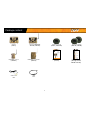 4
4
-
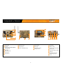 5
5
-
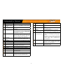 6
6
-
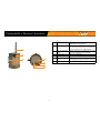 7
7
-
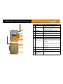 8
8
-
 9
9
-
 10
10
-
 11
11
-
 12
12
-
 13
13
-
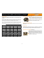 14
14
-
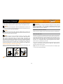 15
15
-
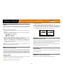 16
16
-
 17
17
-
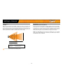 18
18
-
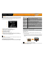 19
19
-
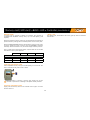 20
20
-
 21
21
-
 22
22
-
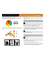 23
23
-
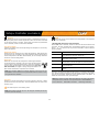 24
24
-
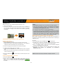 25
25
-
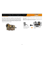 26
26
-
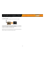 27
27
-
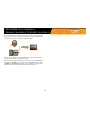 28
28
-
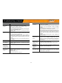 29
29
-
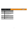 30
30
-
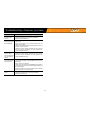 31
31
-
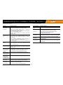 32
32
-
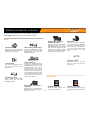 33
33
-
 34
34
-
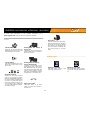 35
35
-
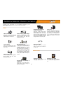 36
36
-
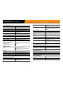 37
37
-
 38
38
-
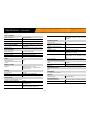 39
39
-
 40
40
-
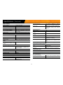 41
41
-
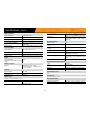 42
42
-
 43
43
-
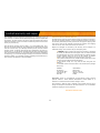 44
44


SKYPOINT Tiny-Plus Manuale utente
- Categoria
- Fotocamere per sport d'azione
- Tipo
- Manuale utente
in altre lingue
- English: SKYPOINT Tiny-Plus User manual
- français: SKYPOINT Tiny-Plus Manuel utilisateur
Altri documenti
-
SPYPOINT LINK-S-DARK Guida utente
-
Dörr WIRELESS GAME MOTION DETECTOR Manuale utente
-
-
Simrad RS100 / RS100-B Istruzioni per l'uso
-
Alpine APF-X303VW Guida di riferimento
-
 TREK BIKES ROCKSHOX BOXXER Manuale del proprietario
-
Teleco Flatsat Komfort Manuale utente
-
Vibe Monobox III Manuale utente
-
Teleco Flatsat Elegance Manuale utente
-
ProLights Smartower Scheda dati
