Danfoss CF-RC Remote Controller Guida d'installazione
- Tipo
- Guida d'installazione

088U0220
GB
Instruction CF-RC Remote Controller
D
Instruktion CF-RC Fernbedienung
DK
Vejledning CF-RC Fjernbetjening
F
Instruction Commande à distance CF-RC
SE
Bruksanvisning CF-RC Fjärrkontroll
PL
Instrukcja obsługi pilota CF-RC
NL
Handleiding CF-RC Afstandsbediening
I
Istruzioni Regolatore a distanza CF-RC

VI.UH.M5.1C Produced by Danfoss Floor Heating Hydronics 08.2009
1
GB
GB
Instruction ............................................................ 3
D
Instruktion ..........................................................19
DK
Vejledning ...........................................................37
F
Instruction ..........................................................53
SE
Bruksanvisning ...................................................69
PL
Instrukcja obsługi ...............................................85
NL
Handleiding ......................................................101
I
Istruzioni ...........................................................119

2
VI.UH.M5.1C Produced by Danfoss Floor Heating Hydronics 08.2009

Instruction CF-RC Remote Controller
VI.UH.M5.1C Produced by Danfoss Floor Heating Hydronics 08.2009
3
GB
GB
Index
10. Figures and illustrations ......................................................A1-A2
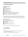
1. Functional Overview ...................................................................... 4
2. Installation ..................................................................................... 5
3. Transmission Test ........................................................................... 6
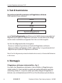
4. Mounting ......................................................................................... 6
5. Menus ............................................................................................. 7
5.1 Rooms .............................................................................................................................. 7
5.2 Program ........................................................................................................................... 9
5.3 Setup ..............................................................................................................................13
5.4 Alarms ............................................................................................................................15
6. Uninstallation .............................................................................. 16
7. Other products for the CF2 system and abbreviations ............. 17
8. Specifications ................................................................................ 17
9. Troubleshooting ........................................................................... 18

4
Instruction CF-RC Remote Controller
VI.UH.M5.1C Produced by Danfoss Floor Heating Hydronics 08.2009
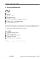
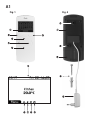
1. Functional Overview
Front – fig. 1
Display
Soft key 1
Soft key 2
Up/down selector
Left/right selector
Icon for system alarm
Icon for communication with Master Controller
Icon for switch to 230V power supply
Icon for low battery level
Note: The Remote Controller has a self-explanatory menu structure, and all settings are easily
carried out with the up/down and left/right selectors in combination with the functions of
the soft keys, which are shown above them in the display.
Back – fig. 2
Back plate/docking station
Battery compartment
Screw hole for wall mounting
Screw and wall plug
Transformer/power supply plug
Note: Remove the strip to connect the enclosed batteries.

Instruction CF-RC Remote Controller
VI.UH.M5.1C Produced by Danfoss Floor Heating Hydronics 08.2009
5
GB
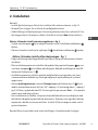
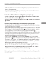
2. Installation
Note:
• Install the Remote Controller after you have installed all the Room Thermostats, see g. 5-b
• Remove the strip to connect the enclosed batteries
• Carry out the assignment of the Remote Controller to the Master Controller within a
distance of 1½m
• When the back light in the display is out, the rst touch of a button only activates this light
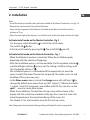
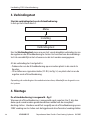
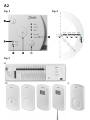
Activate Install mode on the Master Controller - fig. 3
• Use the menu selection button to select the Install mode.
The install LED flashes
• Activate Install mode by pressing OK . The install LED goes ON
Activate Install mode on the Remote Controller - fig. 1
• When the batteries have been connected, follow the installation guide,
beginning with the selection of language
• After the installation process, set time and date. Use the up/down selector
and the left/right selector to carry out the settings. Confirm settings with
OK activated by soft key 1 ( )
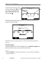
• The installation process is concluded with the opportunity to name the
rooms in which the Room Thermostats are placed. This makes access to and
handling of the system very easy
• In the Name rooms menu, activate the change menu with soft key 2 ( ) to
change the default room names from e.g. MC1 Output 1.2 (Master Controller
1, output 1 and 2) to living room, and conrm with OK. You can also use the
spell…. menu to create other names
• When the installation is nished the start up screen will be shown in the
display with the actual time and date on the top. The screen also shows the
actual temperature in the room from the top of the rooms list.
See chapter 5.3 to select another room for the start up screen
Note: Keeping a button activated during settings will make the value change faster

6
Instruction CF-RC Remote Controller
VI.UH.M5.1C Produced by Danfoss Floor Heating Hydronics 08.2009
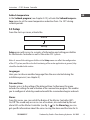
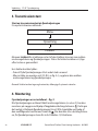
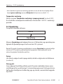
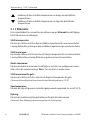
3. Transmission Test
Initiate a transmission test on the Remote Controller
From the start-up screen, activate the:
Menu
Setup
Link test
Link test menu to activate a test of the wireless transmission between the
Master Controller and the Remote Controller. The status of the link test will be
displayed right after the test has been carried through.
If the link test is not successful:
• Try to relocate the Remote Controller in the room
• Or install a Repeater Unit (CF-RU, see g. 5 c), and place it between the Master
Controller and the Remote Controller
Note: The link test may take a few minutes depending on the size of the system
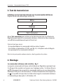
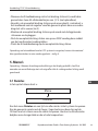
4. Mounting
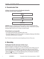
The Remote Controller has been installed – fig. 2
When the Remote Controller has been installed to the
Master Controller (see chapter 2), it can be mounted on the wall by means of
the back plate/docking station . This makes it possible to connect the Re-
mote Controller to a 230V power supply with the included transformer/power
supply plug . When it is not in the docking station, the Remote Controller is
powered by two AA Alkaline 1.5V batteries.

Instruction CF-RC Remote Controller
VI.UH.M5.1C Produced by Danfoss Floor Heating Hydronics 08.2009
7
GB
• Before you place the back plate/docking station on the wall, verify the trans-
mission to the Master Controller from the desired location by carrying out a
link test (see chapter 3)
• Mount the back plate/docking station on the wall with the screws and wall
plugs
• Connect the docking station to a 230V power supply outlet by means of the
transformer/power supply plug
• Place the Remote Controller in the docking station
Note: To extend the transmission range of the CF2 system, up to three Repeater Units can be
installed in a chain – see g. 4
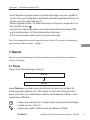
5. Menus
Note: When the back light in the display is out, the rst touch of a button only activates this light.
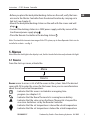
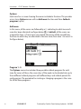
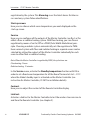
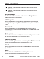
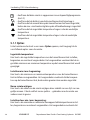
5.1 Rooms
From the start-up screen, activate the:
Menu
Rooms
Rooms menu to access a list of all the rooms in the system. Select the desired
room with OK to enter the screen for that room. Here you can see information
about the set and actual temperatures:
: Indicates that this room is included in an ongoing time
program (see chapter 5.2)
: Indicates that the Room Thermostat is running low on battery
: Indicates that the value set on the Room Thermostat is beyond the
max./min. limitations set by the Remote Controller
: Indicates that the set temperature is above the actual tempe rature
: Indicates that the set temperature is below the actual temperature

8
Instruction CF-RC Remote Controller
VI.UH.M5.1C Produced by Danfoss Floor Heating Hydronics 08.2009
5.1.1 Options
From the room screen, you can activate an Options menu with access to
several room options:
Set temperature:
Here you can set and lock the set temperature for the Room Thermostat.
Locking prevents adjustment of the set temperature on the Room Thermostat.
Set Min/Max:
Here you can set and lock the minimum and maximum temperatures for the
Room Thermostat. Locking prevents adjustment beyond these limits on the
Room Thermostat.
Change room name:
Here you can change the room names by means of a list of possible room
names or you can use the spell..... menu to key in other names.
Set floor Min/Max:
Here you can set and lock the minimum and maximum floor surface tempera-
tures.
Note: Only available with the Room Thermostat with infrared floor sensor, CF-RF
Setback:
Here you can choose to override the next or ongoing setback period (see chap-
ter 5.2.2).
Cooling:
Here you can disable the cooling function for the room in question.
Note: Only available when the Master Controller is in cooling mode

Instruction CF-RC Remote Controller
VI.UH.M5.1C Produced by Danfoss Floor Heating Hydronics 08.2009
9
GB
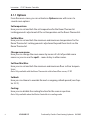
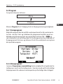
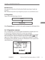
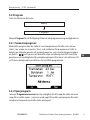
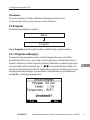
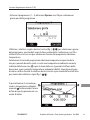
5.2 Program
From the start-up screen, activate the:
Menu
Program
Program menu to view the two time programming options:
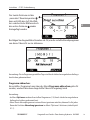
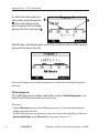
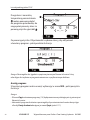
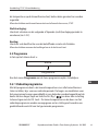
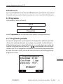
5.2.1 Period program:
With this program, you can set the room temperature for all Room Thermo-
stats during e.g. a holiday. The start and end date for the program is easily set
in a calendar by means of the up/down and left/right selectors (g. 1- / )
and by conrming each setting with OK. The room temperature and the dura-
tion of the period program are illustrated and finally activated from a detailed
overview for the created program:
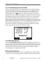
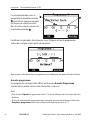
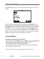
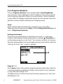
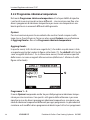
5.2.2 Setback program:
In the Program setback menu, you have the opportunity to divide the die rent
rooms into up to six dierent zones - each zone with up to three dierent setback
programs for reduced room temperature at dierent times during the day.

10
Instruction CF-RC Remote Controller
VI.UH.M5.1C Produced by Danfoss Floor Heating Hydronics 08.2009
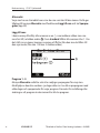
Options:
Each zone has a screen showing the rooms included in the zone. This provides
access to an Options menu with an Add room function and three Setback
programs (up to).
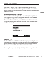
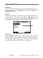
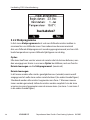
Add room:
In this menu, all the rooms are followed by a ( ) indicating to what zone each
room has been allocated (see gure below ). As default, all the rooms are
assigned to Zone 1. If new zones are created, the rooms will be moved from
the zone to which they are allocated to the new zone (from zone 1 to zone 3 in
the figure below).
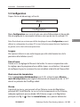
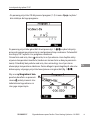
Program 1 - 3:
The Options menu also includes three possible setback programs for each
zone. By means of these, the seven days of the week can be divided into up to
three dierent setback programs with dierent days and setback periods for
each program. The procedure for creating or changing a program is the same
for all the three programs:

Instruction CF-RC Remote Controller
VI.UH.M5.1C Produced by Danfoss Floor Heating Hydronics 08.2009
11
GB
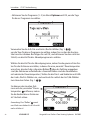
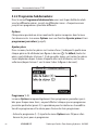
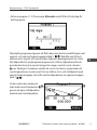
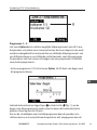
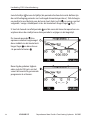
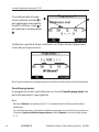
• Activate program (1- 3) from the Options menu with OK to select the days for
this program:
Use the up/down and left/right selectors (g. 1- / ) to select the days for
this program by moving them above the horizontal line. Conrm with OK, and
activate the next step to select the time for the setback program.
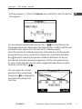
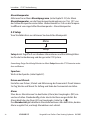
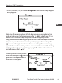
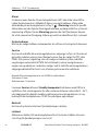
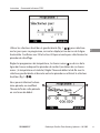
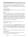
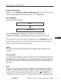
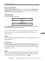
Select the time for the setback program by setting the times for the periods
during which you want a normal room temperature, indicated by the black
bars above the time line (the periods outside the black bars are the set-
back periods with reduced room temperature). Set the start and end times
by means of the left/right selector and by toggling between them using the
up/down selector (g. 1- / ).
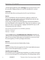
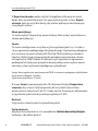
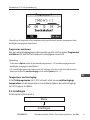
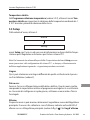
You can remove the second
period with the normal room
temperature by changing the
end time of this period to its
start time:

12
Instruction CF-RC Remote Controller
VI.UH.M5.1C Produced by Danfoss Floor Heating Hydronics 08.2009
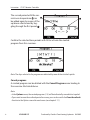
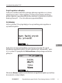
The second period with the nor-
mal room temperature can
be added again by means of the
up/down selector and by tog-
gling through the first period .
Conrm the selected time periods with OK to activate the created
program from this overview:
Note: The days selected in the program are indicated by more distinct initial capitals
Cancel program:
A created program can be deleted with the Cancel Program menu leading to
the overview illustrated above.
Note:
• In the Options menu, the created programs (1-3) will be indicated by more distinct capitals
• If you want to override a setback period in a room, you can do so with the Override setback
function in the Options menu for each room (see chapter 5.1.1)

Instruction CF-RC Remote Controller
VI.UH.M5.1C Produced by Danfoss Floor Heating Hydronics 08.2009
13
GB
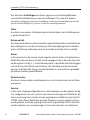
Setback temperature
In the Setback program (see chapter 5.2.2), activate the Setback tempera-
ture menu to set the room temperature reduction from 1 to 10°C during
setback periods.
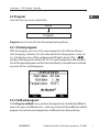
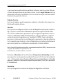
5.3 Setup
From the start-up screen, activate the:
Menu
Setup
Setup menu with access to a variety of information and setting possibilities
for the Remote Controller as well as the entire CF2 system.
Note: As some of the setting possibilities in the Setup menu can aect the conguration
of the CF2 system, and thus also the functioning of the entire application in general, they
should be handled with caution
Languages:
Here you can choose another language than the one selected during the
installation process (see chapter 2).
Date and time:
Provides access to the setting of the date and time. Furthermore, this menu
includes the settings for and activation of the summertime program. This enables
you to congure at what day, week and month the summertime begins and ends.
Alarm:
From this menu, you can switch the Buzzer of the Master Controller (MC)
On/O. The sound only occurs in case of an alarm, also indicated by the red
alarm LED on the Master Controller (see g. 3- ). In the Alarm log, you can
get specific information about the error causing the alarm and the time for its

14
Instruction CF-RC Remote Controller
VI.UH.M5.1C Produced by Danfoss Floor Heating Hydronics 08.2009
registration by the system. This Alarm log saves the latest alarms for later ac-
cess and easy system failure identification.
Start-up screen:
Here you can choose which room temperature you want displayed on the
start-up screen.
Service:
Here you can congure all the outputs of the Master Controller (see g. 5-a) for
either a oor or radiator heating system. With oor heating, you can choose
regulation by means of an On/O or a PWM (Pulse Width Modulation) prin-
ciple. Choosing a radiator system automatically sets the regulation to PWM.
Even a mixed system with floor and radiator heating in separate rooms can be
selected by setting the outputs of the Master Controller individually for each
room to either floor or radiator heating.
Note: When the Master Controller is regulated by PWM, the cycle times are:
Floor heating: 2 hours
Radiator heating: 15 minutes.
In the Service menu, activate the Standby temperature function with OK in
order to set a fixed room temperature for all the Room Thermostats to 5 – 35°C
when the Global standby input is activated on the Master Controller (see
instruction for Master Controller, CF-MC for installation details).
Contrast:
Here you can adjust the contrast of the Remote Controller display.
Link test:
Activates a link test to the Master Controller to test the wireless transmission to
and from the Remote Controller (see chapter 3).

Instruction CF-RC Remote Controller
VI.UH.M5.1C Produced by Danfoss Floor Heating Hydronics 08.2009
15
GB
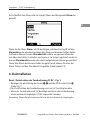
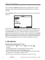
Identify Master Controller:
This function enables you to identify one specific Master Controller in a system
of up to three Master Controllers. When this function is activated, the Master
Controller, whose identity you wish to reveal, will ash all the output LEDs
from 1 to 10 and back again several times for easy identification.
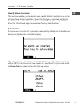
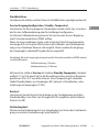
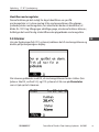
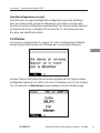
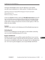
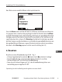
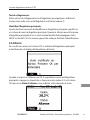
5.4 Alarms
If an error occurs in the CF2 system, it is indicated by the Master Controller and
directly on the Remote Controller Display:
When the alarm is acknowledged with OK, the Buzzer of the Master Controller
will go O (if set to Sound On, see chapter 5.3), and the CF2 system will switch
to Alarm status as indicated on the start-up screen:

16
Instruction CF-RC Remote Controller
VI.UH.M5.1C Produced by Danfoss Floor Heating Hydronics 08.2009
This indication of Alarm on the Remote Controller and the indication on the
Master Controller will continue until the error that caused the alarm has been
fixed.
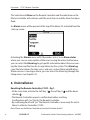
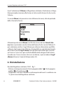
An Alarms menu will be present at the top of the Menu list activated from the
start-up screen:
Activating this Alarms menu with OK provides access to an Alarm status
where you can see a description of the error causing the alarm Furthermore,
you can select the Alarm log to get specific information about the error caus-
ing the alarm and the time for its registration by the system. This Alarm log
saves the latest alarms for later access and easy system failure identification.
When no error is causing an alarm, you can access the Alarm log through the
Setup menu (see chapter 5.3).
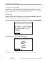
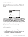
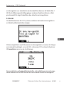
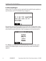
6. Uninstallation
Resetting the Remote Controller, CF-RC – fig 1:
• At the same time, activate the Soft key 1 , the soft key 2 and the down
selector .
• The Remote Controller requests conrmation before resetting.
Confirmation with “yes” Resets the Remote Controller.
• By conrming Reset with “yes” the Remote Controller is now ready for instal-
lation to a Master Controller, CF-MC.
Note: Please see the Master Controller instruction for further details!

Instruction CF-RC Remote Controller
VI.UH.M5.1C Produced by Danfoss Floor Heating Hydronics 08.2009
17
GB
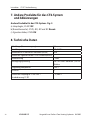
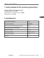
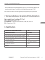
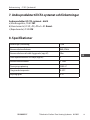
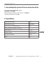
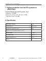
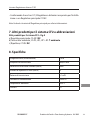
7. Other products for the CF2 system
and abbreviations
Other products for the CF2 system - fig. 5
a) Master Controller, CF-MC: MC
b) Room Thermostat, CF-RS, -RP, - RD and -RF: Room T.
c) Repeater Unit, CF-RU: RU
8. Specifications
Cable length (power supply) 1.8m
Transmission frequency 868.42MHz
Transmission range in buildings (up to) 30m
Number of Repeater Units in a chain (up to) 3
Transmission power < 1mW
Supply voltage 230V a.c.
Ambient temperature 0-50°C
IP class 21

18
Instruction CF-RC Remote Controller
VI.UH.M5.1C Produced by Danfoss Floor Heating Hydronics 08.2009
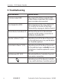
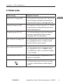
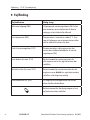
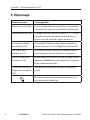
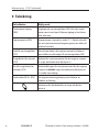
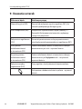
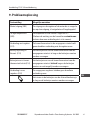
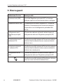
9. Troubleshooting
Error Indication Possible Causes
Actuator/output (E03) The output of the Master Controller (MC)
or the actuator connected to this output is
short-circuited or disconnected.
Low temperature (E05) The temperature in the room is below 5°C.
(Try to verify the function of the Room
Thermostat by carrying out a link test from it)
Link to Master Controller (E12) The Room Thermostat in the indicated
room has lost the wireless connection to
the Master Controller (MC)
Low bat. in Room T. (E13) The battery level of the Room Thermostat
for the indicated room is low, and the batte-
ries should be replaced
Critical bat. in Room T. (E14) The battery level of the Room Thermostat
for the indicated room is critically low, and
the batteries should be replaced as soon as
possible
Link between MCs (E24) The indicated Master Controllers have lost
their wireless connection
The battery level of the Remote Controller
is low, and the batteries should be replaced

Instruktion CF-RC Fernbedienung
VI.UH.M5.1C Hergestellt von Danfoss Floor Heating Hydronics 08.2009
19
D
D
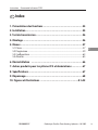
Inhaltsverzeichnis
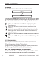
1. Funktionsübersicht ...................................................................... 20
2. Installation ................................................................................... 20
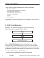
3. Funk-Verbindungstest ................................................................. 22
4. Montage - Fig. 2 ............................................................................ 23
5. Menüs ............................................................................................ 23
5.1 Räume ............................................................................................................................24
5.2 Programme zur Temperaturabsenkung ............................................................25
5.3 Setup ..............................................................................................................................30
5.4 Alarme ............................................................................................................................32
6. Deinstallation ............................................................................... 33
7. Andere Produkte für das CF2-System und Abkürzungen ......... 34
8. Technische Daten .......................................................................... 34
9. Fehlersuche ................................................................................... 34
10. Bilder und Zeichnungen ..................................................... A1-A2
La pagina sta caricando ...
La pagina sta caricando ...
La pagina sta caricando ...
La pagina sta caricando ...
La pagina sta caricando ...
La pagina sta caricando ...
La pagina sta caricando ...
La pagina sta caricando ...
La pagina sta caricando ...
La pagina sta caricando ...
La pagina sta caricando ...
La pagina sta caricando ...
La pagina sta caricando ...
La pagina sta caricando ...
La pagina sta caricando ...
La pagina sta caricando ...
La pagina sta caricando ...
La pagina sta caricando ...
La pagina sta caricando ...
La pagina sta caricando ...
La pagina sta caricando ...
La pagina sta caricando ...
La pagina sta caricando ...
La pagina sta caricando ...
La pagina sta caricando ...
La pagina sta caricando ...
La pagina sta caricando ...
La pagina sta caricando ...
La pagina sta caricando ...
La pagina sta caricando ...
La pagina sta caricando ...
La pagina sta caricando ...
La pagina sta caricando ...
La pagina sta caricando ...
La pagina sta caricando ...
La pagina sta caricando ...
La pagina sta caricando ...
La pagina sta caricando ...
La pagina sta caricando ...
La pagina sta caricando ...
La pagina sta caricando ...
La pagina sta caricando ...
La pagina sta caricando ...
La pagina sta caricando ...
La pagina sta caricando ...
La pagina sta caricando ...
La pagina sta caricando ...
La pagina sta caricando ...
La pagina sta caricando ...
La pagina sta caricando ...
La pagina sta caricando ...
La pagina sta caricando ...
La pagina sta caricando ...
La pagina sta caricando ...
La pagina sta caricando ...
La pagina sta caricando ...
La pagina sta caricando ...
La pagina sta caricando ...
La pagina sta caricando ...
La pagina sta caricando ...
La pagina sta caricando ...
La pagina sta caricando ...
La pagina sta caricando ...
La pagina sta caricando ...
La pagina sta caricando ...
La pagina sta caricando ...
La pagina sta caricando ...
La pagina sta caricando ...
La pagina sta caricando ...
La pagina sta caricando ...
La pagina sta caricando ...
La pagina sta caricando ...
La pagina sta caricando ...
La pagina sta caricando ...
La pagina sta caricando ...
La pagina sta caricando ...
La pagina sta caricando ...
La pagina sta caricando ...
La pagina sta caricando ...
La pagina sta caricando ...
La pagina sta caricando ...
La pagina sta caricando ...
La pagina sta caricando ...
La pagina sta caricando ...
La pagina sta caricando ...
La pagina sta caricando ...
La pagina sta caricando ...
La pagina sta caricando ...
La pagina sta caricando ...
La pagina sta caricando ...
La pagina sta caricando ...
La pagina sta caricando ...
La pagina sta caricando ...
La pagina sta caricando ...
La pagina sta caricando ...
La pagina sta caricando ...
La pagina sta caricando ...
La pagina sta caricando ...
La pagina sta caricando ...
La pagina sta caricando ...
La pagina sta caricando ...
La pagina sta caricando ...
La pagina sta caricando ...
La pagina sta caricando ...
La pagina sta caricando ...
La pagina sta caricando ...
La pagina sta caricando ...
La pagina sta caricando ...
La pagina sta caricando ...
La pagina sta caricando ...
La pagina sta caricando ...
La pagina sta caricando ...
La pagina sta caricando ...
La pagina sta caricando ...
La pagina sta caricando ...
La pagina sta caricando ...
La pagina sta caricando ...
La pagina sta caricando ...
La pagina sta caricando ...
La pagina sta caricando ...
La pagina sta caricando ...
-
 1
1
-
 2
2
-
 3
3
-
 4
4
-
 5
5
-
 6
6
-
 7
7
-
 8
8
-
 9
9
-
 10
10
-
 11
11
-
 12
12
-
 13
13
-
 14
14
-
 15
15
-
 16
16
-
 17
17
-
 18
18
-
 19
19
-
 20
20
-
 21
21
-
 22
22
-
 23
23
-
 24
24
-
 25
25
-
 26
26
-
 27
27
-
 28
28
-
 29
29
-
 30
30
-
 31
31
-
 32
32
-
 33
33
-
 34
34
-
 35
35
-
 36
36
-
 37
37
-
 38
38
-
 39
39
-
 40
40
-
 41
41
-
 42
42
-
 43
43
-
 44
44
-
 45
45
-
 46
46
-
 47
47
-
 48
48
-
 49
49
-
 50
50
-
 51
51
-
 52
52
-
 53
53
-
 54
54
-
 55
55
-
 56
56
-
 57
57
-
 58
58
-
 59
59
-
 60
60
-
 61
61
-
 62
62
-
 63
63
-
 64
64
-
 65
65
-
 66
66
-
 67
67
-
 68
68
-
 69
69
-
 70
70
-
 71
71
-
 72
72
-
 73
73
-
 74
74
-
 75
75
-
 76
76
-
 77
77
-
 78
78
-
 79
79
-
 80
80
-
 81
81
-
 82
82
-
 83
83
-
 84
84
-
 85
85
-
 86
86
-
 87
87
-
 88
88
-
 89
89
-
 90
90
-
 91
91
-
 92
92
-
 93
93
-
 94
94
-
 95
95
-
 96
96
-
 97
97
-
 98
98
-
 99
99
-
 100
100
-
 101
101
-
 102
102
-
 103
103
-
 104
104
-
 105
105
-
 106
106
-
 107
107
-
 108
108
-
 109
109
-
 110
110
-
 111
111
-
 112
112
-
 113
113
-
 114
114
-
 115
115
-
 116
116
-
 117
117
-
 118
118
-
 119
119
-
 120
120
-
 121
121
-
 122
122
-
 123
123
-
 124
124
-
 125
125
-
 126
126
-
 127
127
-
 128
128
-
 129
129
-
 130
130
-
 131
131
-
 132
132
-
 133
133
-
 134
134
-
 135
135
-
 136
136
-
 137
137
-
 138
138
-
 139
139
-
 140
140
-
 141
141


Danfoss CF-RC Remote Controller Guida d'installazione
- Tipo
- Guida d'installazione
in altre lingue
- français: Danfoss CF-RC Remote Controller Guide d'installation
- Deutsch: Danfoss CF-RC Remote Controller Installationsanleitung
- Nederlands: Danfoss CF-RC Remote Controller Installatie gids
- dansk: Danfoss CF-RC Remote Controller Installationsvejledning
- polski: Danfoss CF-RC Remote Controller Instrukcja instalacji
- svenska: Danfoss CF-RC Remote Controller Installationsguide
Documenti correlati
-
Danfoss CF-RD Room Thermostat Guida d'installazione
-
-
-
Danfoss CF-RF Room Thermostat Guida d'installazione
-
-
-
-
-
-