
© Copyright 2003, Zenith Electronics Corporation
Installation and Operating Guide | Warranty
Model Number | H20F50DT | HealthView
TM
TV
table of contents
page
5

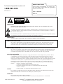
WARNING:
TO REDUCE THE RISK OF ELECTRIC SHOCK DO NOT REMOVE COVER (OR BACK). NO USER SERVICEABLE PARTS INSIDE.
REFER TO QUALIFIED SERVICE PERSONNEL.
The lightning flash with arrowhead symbol, within an equilateral triangle, is intended to alert the user to the presence
of uninsulated “dangerous voltage” within the product’s enclosure that may be of sufficient magnitude to constitute a
risk of electric shock to persons.
The exclamation point within an equilateral triangle is intended to alert the user to the presence of important operating
and maintenance (servicing) instructions in the literature accompanying the appliance.
WARNING:
TO PREVENT FIRE OR SHOCK HAZARDS, DO NOT EXPOSE THIS PRODUCT TO RAIN OR MOISTURE.
POWER CORD POLARIZATION:
This product is equipped with a 3-wire grounding-type alternating current line plug. This plug will fit into the power
outlet only one way. This is a safety feature. If you are unable to insert the plug fully into the outlet, contact your
electrician to replace your obsolete outlet. Do not defeat the safety purpose of the three-wire ground type plug.
NOTE TO CABLE/TV INSTALLER:
This reminder is provided to call the cable TV system installer’s attention to Article 820-40 of the National Electric Code
(U.S.A.). The code provides guidelines for proper grounding and, in particular, specifies that the cable ground shall be
connected to the grounding system of the building, as close to the point of the cable entry as practical.
REGULATORY INFORMATION:
This equipment has been tested and found to comply with the limits for a Class B digital device, pursuant to Part 15
of the FCC Rules. These limits are designed to provide reasonable protection against harmful interference when the
equipment is operated in a residential installation. This equipment generates, uses and can radiate radio frequency
energy and, if not installed and used in accordance with the instruction manual, may cause harmful interference to radio
communications. However, there is no guarantee that interference will not occur in a particular installation. If this
equipment does cause harmful interference to radio or television reception, which can be determined by turning
the equipment off and on, the user is encouraged to try to correct the interference by one or more of the following
measures:
• Reorient or relocate the receiving antenna.
• Increase the separation between the equipment and receiver.
• Connect the equipment into an outlet on a circuit different from that to which the
receiver is connected.
• Consult the dealer or an experienced radio/TV technician for help.
CAUTION:
Do not attempt to modify this product in any way without written authorization from Zenith Electronics Corporation.
Unauthorized modification could void the user’s authority to operate this product.
COMPLIANCE:
The responsible party for this product’s compliance is:
Zenith Electronics Corporation, 2000 Millbrook Drive, Lincolnshire, IL 60069, USA. Phone: 1-847-941-8000.
WARNING
RISK OF ELECTRIC SHOCK
DO NOT OPEN
3-WIRE COMM-WARN B-2/02
HealthView
TM
is a trademark of Zenith Electronics Corporation
© Copyright 2003 Zenith Electronics Corporation
RECORD THE MODEL NUMBER
The serial number of this HealthView
TM
TV is located on the
back of the cabinet. For future reference, we suggest that you
record the serial number here:
MODEL NO. H20F50DT
SERIAL NO.____________________________________
For Customer Support/Service please call:
1-888-865-3026
www.zenith.com

Important safety instructions shall be provided with each apparatus. This information shall be given in a separate booklet or sheet, or be
located before any operating instructions in an instruction for installation for use and supplied with the apparatus.
This information shall be given in a language acceptable to the country where the apparatus is intended to be used. The important safety
instructions shall be entitled “Important Safety Instructions”. The following safety instructions shall be included where applicable, and,
when used, shall be verbatim as follows. Additional safety information may be included by adding statements after the end of the following
safety instruction list. At the manufacturer’s option, a picture or drawing that illustrates the intent of a specific safety instruction may be
placed immediately adjacent to that safety instruction:
1. Read these instructions.
2. Keep these instructions.
3. Heed all warnings.
4. Follow all instructions.
5. Do not use this apparatus near water.
6. Clean only with dry cloth.
7. Do not block any ventilation openings. Install in accordance with the manufacturer’s instructions.
8. Do not install near any heat sources such as radiators, heat registers, stoves, or other apparatus (including amplifiers)
that produce heat.
9. Do not defeat the safety purpose of the polarized or grounding-type plug. A polarized plug has two blades with one
wider than the other. A grounding type plug has two blades and a third grounding prong. The wide blade or the third prong
are provided for your safety. If the provided plug does not fit into your outlet, consult an electrician for replacement of
the obsolete outlet.
10. Protect the power cord from being walked on or pinched particularly at plugs, convenience receptacles, and the point
where they exit from the apparatus.
11. Only use attachments/accessories specified by the manufacturer.
12. Use only with the cart, stand, tripod, bracket, or table specified by the manufacturer, or sold with the apparatus.
When a cart is used, use caution when moving the cart/apparatus combination to avoid injury from type-over.
IMPORTANT SAFETY INSTRUCTIONS
PORTABLE CART WARNING
(Continued on next page)
P A G E 3
IMPORTANT SAFETY INSTRUCTIONS

IMPORTANT SAFETY INSTRUCTIONS
13. Unplug this apparatus during lightning storms or when unused for long periods of time.
14. Refer all the servicing to qualified service personnel. Servicing is required when the apparatus has been damaged
in any way, such as power-supply cord or plug is damaged, liquid has been spilled or objects have fallen into the
apparatus, the apparatus has exposed to rain or moisture, does not operate normally, or has been dropped.
15. CAUTION concerning the Power Cord:
Most appliances recommend they be placed upon a dedicated circuit; that
is, a single outlet circuit which powers only that appliance and has no
additional outlets or branch circuits. Check the specification page of
this owner’s manual to be certain.
Do not overload wall outlets. Overloaded wall outlets, loose or damage
wall outlets, extension cords, frayed power cords, or damaged or
cracked wire insulation are dangerous. Any of these conditions could
result in electric shock or fire. Periodically examine the cord of your
appliance, and if its appearance indicates damage or deterioration,
unplug it, discontinue use of the appliance, and have the cord replaced
with an exact replacement part by an authorized servicer.
Protect the power cord from physical or mechanical abuse, such as being
twisted, kinked, pinched, closed in a door, or walked upon. Pay
particular attention to plugs, wall outlets, and the point where the
cords exits the appliance.
16. Outdoor Use Marking:
WARNING - To reduce the risk of fire or electric shock, do not expose this appliance to rain or moisture.
17. Wet Location Marking:
Apparatus shall not be exposed to dripping or splashing and no objects filled with liquids, such as vases, shall
be placed on the apparatus.
P A G E 4

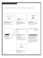
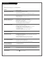
PAGE 5
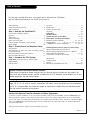
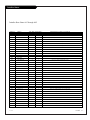
Table of Contents
Safety Warnings . . . . . . . . . . . . . . . . . . . . . . . . . . . 2
Important Safety Instructions . . . . . . . . . . . . . . . . 3 - 4
Table of Contents . . . . . . . . . . . . . . . . . . . . . . . . . . 5
Step 1. Hook Up the HealthView TV
TV and other Equipment Hookups
Antenna . . . . . . . . . . . . . . . . . . . . . . . . . . . . . . . . 6
Cable Service . . . . . . . . . . . . . . . . . . . . . . . . . . . . . 7
Antenna with VCR . . . . . . . . . . . . . . . . . . . . . . . . . . 8
Cable service with VCR . . . . . . . . . . . . . . . . . . . . . . . 9
External Speaker Connection (8-ohm output) . . . . . . . . 9
Pillow Speaker . . . . . . . . . . . . . . . . . . . . . . . . . . . 10
Step 2. Channel Search and Reception Setup
Auto Program . . . . . . . . . . . . . . . . . . . . . . . . . . . . 11
(Select Antenna, or cable service then do channel search)
Front Panel Controls . . . . . . . . . . . . . . . . . . . . . . . . 12
Optional Installer’s Remote Key Functions . . . . . . . . . . 13
On-Screen Menus Overview . . . . . . . . . . . . . . . . . . . 14
Step 3. Customize the TV’s Features
Setup Menu (Start with page 11, Auto Program)
Add/Del/Blank . . . . . . . . . . . . . . . . . . . . . . . . . . . 15
Channel Labels . . . . . . . . . . . . . . . . . . . . . . . . . . . 16
Clock Set . . . . . . . . . . . . . . . . . . . . . . . . . . . . . . . 17
On/Off Timers . . . . . . . . . . . . . . . . . . . . . . . . . . . 18
Captions (Caption/Text) . . . . . . . . . . . . . . . . . . . . . 19
Language . . . . . . . . . . . . . . . . . . . . . . . . . . . . . . . 20
Video Menu . . . . . . . . . . . . . . . . . . . . . . . . . . . . . 21
FM Radio Menus . . . . . . . . . . . . . . . . . . . . . . 22 - 23
Installer Parental Control Menu . . . . . . . . . . . . 24 - 25
Other Menus and On-Screen Displays . . . . . . . . . . . . 26
Managing the Channel Banks . . . . . . . . . . . . 27 - 28 - 29
Installer Menus . . . . . . . 30 - 31 - 32 - 33 - 34 - 35 - 36
LT2000 Quickset II Clone Programmer . . . . . . 37 - 38 - 39
Patient Operation Section (Copy for patient usage)
Optional Patient Remote Key Functions . . . . . . . . . . . 40
Optional Patient Remote Key Functions - FM Radio . . . . 41
Patient Parental Control Menu . . . . . . . . . . . . . . 42 - 43
Patient Menus and On-Screen Displays . . . . . . . . . . . . 44
Maintenance . . . . . . . . . . . . . . . . . . . . . . . . . . . . . 45
Troubleshooting . . . . . . . . . . . . . . . . . . . . . . . . . . 46
Glossary . . . . . . . . . . . . . . . . . . . . . . . . . . . . . . . 47
Warranty for HealthView Series TVs . . . . . . . . . Back Cover
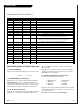
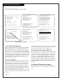
Purchase the Optional Installer’s Remote and Clone Programmer
To perform a normal installation set up, you need an installer’s remote such as the HP602, and the LT2000 Quickset II
Clone Programmer—both are shown and described in later sections. The installer remote allows access to the Installer
menus, User menus, and Source/Channel Bank keys. The installer remote has Menu, Select, and Adjust, and Channel Bank
Keys. The LT2000 Quickset II Clone Programmer is used to duplicate a TV’s setup and install it on another identical TV.
See your Zenith Dealer.
Design and specifications subject to change without prior notice.
Installer/Hospital Note:
Pages 40, 41, 42, 43, and 44 contain information and menus which the patient can use to operate
the TV. It is recommended that these four pages be copied and included with the literature packet
that the hospital provides to the patient.
206-3853
Optional Installer and Patient Remote Controls:
Shown herein are optional remote controls that can be used by the installer and the patient. Be
advise that these remote controls are NOT included with this TV. However, these remotes can be pur-
chased separately, see your Zenith dealer.
Use the steps outlined below as a setup guide and to determine the TV features
that will require adjustment for the needs of the end user

PAGE 6
206-3491-O
Mini glossary
75 OHM RF CABLE The wire that comes from an off-air antenna or cable service provider. Each end looks like a hex shaped nut with a wire
sticking through the middle, and it screws onto the threaded jack on the back of the TV.
A small device that connects a two-wire 300 ohm antenna to a 75 ohm RF jack. They are usually about an inch long with two screws
on one end and a round opening with a wire sticking out on the other end.
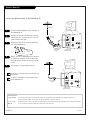
Antenna Hook Up
Connect an off-air antenna to the HealthView TV
If you have a 75 ohm RF cable, then you don’t need
any adapters.
A 300 to 75 ohm adapter is not included with the
Zenith HealthView TV.
300 TO 75 OHM
ADAPTER
ANTENNA
CABLE
M.P.I.
TV Back
Flat wire
(300 ohm)
Antenna
300/75 ohm
Adapter
TV Back Panel
(Expanded View)
PILLOW SPEAKER
TV
SPKR
PILLOW
SPKR
Video
In
Speaker
Out
Audio
In
ANTENNA
CABLE
M.P.I.
TV Back
Antenna
TV Back Panel
(Expanded View)
RF Coaxial Wire
(75ohm)
PILLOW SPEAKER
TV
SPKR
PILLOW
SPKR
Video
In
Speaker
Out
Audio
In
Locate the Antenna/Cable jack on the back of
the HealthView TV.
Connect the antenna wire that runs from the
wall to this jack, according to one of the dia-
grams shown to the right.
Remove the back of the optional remote and
put in two AA batteries.
Plug in the TV. The HealthView TV is designed
to operate on standard current, 120-volt 60
Hertz AC. Do not attempt to operate it on DC
power.
Go to page 11 to Auto Program the TV.
Back of
Remote
1
2
3
4
5

PAGE 7
206-3491-O
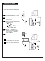
Cable Service (CATV) Hook Up
If you’re using a cable box, leave the TV on channel
3 or 4 and use the cable box to change channels.
If you’re using a cable box, Auto Program might
only find the channel the cable service is on (usual-
ly channel 3 or 4).
Cable TV
Wall Jack
RF Coaxial Wire
(75ohm)
ANTENNA
CABLE
M.P.I.
TV Back
TV Back Panel
(Expanded View)
PILLOW SPEAKER
TV
SPKR
PILLOW
SPKR
Video
In
Speaker
Out
Audio
In
Cable TV
Wall Jack
Cable Box
In
Out
RF Coaxial Wire
(75ohm)
3 4
output
switch
ANTENNA
CABLE
M.P.I.
TV Back
TV Back Panel
(Expanded View)
PILLOW SPEAKER
TV
SPKR
PILLOW
SPKR
Video
In
Speaker
Out
Audio
In
Locate the Antenna/Cable jack on the back
of the HealthView TV.
Connect the cable service wire that runs
from the wall, according to one of the dia-
grams to the right.
Remove the back of the optional remote and
put in two AA batteries.
Plug in the TV. The HealthView TV is
designed to operate on standard current,
120-volt 60 Hertz AC. Do not attempt to
operate it on DC power.
Go to page 11 to Auto Program the TV.
Back of
Remote
1
2
3
4
5
Connect cable service to the HealthView TV

PAGE 8
206-3491-O
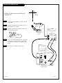
Antenna with VCR Hook Up
Connect an off-air antenna and VCR to the
HealthView TV
Locate the Antenna/Cable in jack on the back
of the VCR.
Connect the antenna wire according to one of
the diagrams to the right.
Remove the back of the optional remote and
put in two AA batteries.
Plug in the TV. The HealthView TV is designed
to operate on standard current, 120-volt 60
Hertz AC. Do not attempt to operate it on DC
power.
Go to page 11 to Auto Program the TV.
Back of
Remote
1
2
3
4
5
In
Out
Audio
Video
3 4
VCR Back
VCR Back AV Panel
output
switch
Round
Or
Flat wire
(300 ohm)
300/75 ohm
Adapter
TV Back
ANTENNA
CABLE
M.P.I.
TV Back Panel
(Expanded View)
PILLOW SPEAKER
TV
SPKR
PILLOW
SPKR
Video
In
Speaker
Out
Audio
In
Antenna

206-3684-A
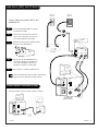
Cable Service (CATV) with VCR Hook Up
Connect Cable service and a VCR to the
HealthView TV
Leave the VCR and the television tuned to channel three
or four and use the cable box to change channels.
Locate the Antenna/Cable in jack on
the back of the VCR.
Connect the wire that runs from the
cable service wall jack, according to
one of the diagrams to the right.
Remove the back of the optional remote
and put in two AA batteries.
Plug in the TV. The HealthView TV is
designed to operate on standard cur-
rent, 120-volt 60 Hertz AC. Do not
attempt to operate it on DC power.
Go to page 11 to Auto Program the TV.
Back of
Remote
1
2
3
4
5
PAGE 9
In
Out
Audio
Video
3 4
VCR Back
VCR Back AV Panel
output
switch
TV Back
ANTENNA
CABLE
M.P.I.
TV Back Panel
(Expanded View)
PILLOW SPEAKER
TV
SPKR
PILLOW
SPKR
Video
In
Speaker
Out
Audio
In
Cable TV
Wall Jack
Cable Box
In
Out
3 4
output
switch
Cable TV
Wall Jack
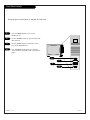
External Speaker Connection (8-ohm)
TV Back
ANTENNA
CABLE
M.P.I.
TV Back Panel
(Expanded View)
PILLOW SPEAKER
TV
SPKR
PILLOW
SPKR
Video
In
Speaker
Out
Audio
In
A/V cables
not included
with TV
8-ohm Speaker In
Speaker Back
Connect Speaker out to an 8-ohm speaker as shown.

PAGE 10
206-3491-O
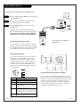
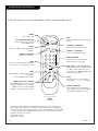
Pillow Speaker Hook Up
Locate the Pillow Speaker Output jack on the back
of the HealthView TV.
Connect an accessory pillow speaker or wired
remote control unit to this 6-pin jack.
Select PILLOW SPKR on the rear panel of the
HealthView TV.
Use a pillow speaker by Curbell, Model A-16455-02 or
other UL recognized pendant control bearing the warning:
“Risk of fire if used in oxygen enriched atmosphere.
Keep pendant control away from oxygen equipment.”
TV
TV Back
ANTENNA
CABLE
M.P.I.
TV Back Panel
(Expanded View)
PILLOW SPEAKER
TV
SPKR
PILLOW
SPKR
Video
In
Speaker
Out
Audio
In
1
2
Connect a pillow speaker to the HealthView TV
3
TV
ON/OFF
CHAN
DOWN
CHAN
UP
(MALE
PLUG)
VOLUME CONTROL
SPKR.
5
1
4
6
2
1
2
3
4
5
6
3
1
5
2
4
6
TV ON/OFF
OPEN
CHAN UP/DATA IN
COMMON
AUDIO OUT
CHAN DOWN
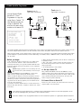
Controlling the TV with mechanical switches
Pin 4 (common) is momentarily connected to pin 1, 3, or 6 via
push-action switches to control On/Off and Channel Up/Down.
These pins are at +13 volts DC (when measured from pin 4) with
the switches open. Current draw is 8 mA when a switch is
closed. (This operation is identical to previous Zenith models
using the 5-Wire Interface except that only +7 volts DC was
supplied and current draw was only 2.5 mA.)
Pillow Speaker Interface
This connector furnishes three control lines and an
audio output. A patient-pendant remote control, or
entertainment audio and nurse call system may be
connected here. All lines are isolated from the AC
power line and earth ground. (Opto-isolators isolate
the control lines, and a transformer isolates the
audio. There are no relays or inductive components in
the control lines.)
Pin no. Purpose
1 External TV On/Off switch
2 (not used)
3 External Channel Up switch or Data in
4 Common connection for control, data,
and audio output.
Impedance to earth ground is a 10-meg resistor
in parallel with a 1100 pf capacitor.
5 Isolated audio output. Nominal 14-ohm source
impedance with short circuit protection. Intended
for a pillow speaker with a low-impedance pad-type
volume control.
6 External Channel Down switch
Pillow speaker not included with
HealthView TV.
3
Controlling the TV with Serial Data
The TV is capable of being controlled by a single-wire,
serial data signal. This is a Zenith patented technology
and is being implemented by certain brands of “smart”
pillow speakers, such as Curbell’s “GEN-II” models.

PAGE 11
206-3747
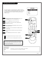
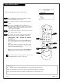
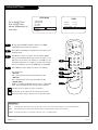
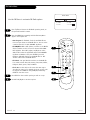
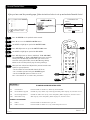
Auto Program (Channel Search)
Use Auto Program to specify Cable TV or Off Air Antenna
incoming signal source and automatically store in the mem-
ory of the TV, all of the channels that are found by the
channel search
With the optional Installer remote control in hand, press
the POWER key to turn on the HealthView TV.
Press the MENU key to show the Setup menu.
Using SELECT on the remote control, highlight Auto
Program on the screen.
Press the Right or Left ADJ (Adjust) arrow to go to the
Auto Program menu.
Using SELECT, choose either Cable TV or Off Air Antenna
on the screen.
Press the Right or Left ADJ arrow to begin the Channel
Search.
Press ENTER when the channel search is complete.
1
2
3
4
5
6
7
123
456
7
0
8
ENTER
9
POWER
TV/FM
FLSHBK
MUTE
VOLUME
CHANNEL
MENU
ADJ ADJ
SELECT
TIMER
BANK
CH PREVIEW
BED 1
BED 2
CC
-
+
-
+
3/5
AUTO PROGRAM
ADD/DEL/BLNK
CH. LABELS
CLOCK SET
TIMER
CAPTIONS
LANGUAGE
Mini glossary
OFF AIR ANTENNA If the patient can only view over-the-air broadcasts, select Antenna.
CABLE If you provide cable service to the patients, select Cable.
Auto Program finds channels being received by the TV tuner.
Cable will not work unless the hospital provides a cable service.
4/6
1
7
2
Optional Installer and Patient Remote Controls:
Shown herein are optional remote controls that can be used by the
installer and the patient. Be advise that these remote controls are
NOT included with this TV. However, these remotes can be purchased
separately, see your Zenith dealer.

PAGE 12
206-3491-O
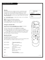
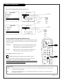
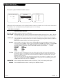
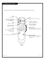
Front Panel Controls
power
channel
volume
captions
4
Press the POWER button to turn on the
HealthView TV.
Use the CHANNEL button to cycle through avail-
able channels.
Use the VOLUME button to adjust the sound
level of the HealthView TV.
Press CAPTIONS repeatedly to turn selected
closed captions option On or Off. (See Captions
page.)
Using the front control panel to operate the television
1
2
3
2
3
1
4

PAGE 13
206-3853
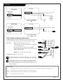
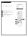
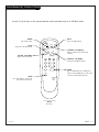
Installer Remote Key Functions
123
456
7
0
8
ENTER
9
POWER
TV/FM
FLSHBK
MUTE
VOLUME
CHANNEL
MENU
ADJ ADJ
SELECT
TIMER
BANK
CH PREVIEW
BED 1
BED 2
CC
-
+
-
+
FLASHBK (FLASHBACK)
Return to the last channel viewed.
POWER
Turns TV On or Off
.
CHANNEL (UP/DOWN)
Tunes to next available channel.
MUTE
Turns sound Off and On, while the picture
remains.
ENTER
Press to view the Channel/Time display or
to remove any on-screen display or menu.
NUMBER KEYPAD
Selects channels directly and enters
numeric values for some options
.
remote control part number
HP602
124-213-06
TIMER
Press repeatedly to adjust TV turn-off time
up to 4-hours.
Use to pick AM/PM in Clock menu.
VOLUME LEFT/RIGHT
Adjusts the sound levels.
CC (CLOSED CAPTIONING)
Press to access closed captions.
Press ENTER to exit.
A quick list of the keys on the optional HP602 installer’s remote and what they do
BANK
Press and repeat to select a Channel
Memory Bank - - 1, 2, 3, or 4 (standby).
MENU/SELECT/ADJ (ADJUST)
Press MENU repeatedly to scroll through
either the Installer, or User menus. Use
SELECT to choose an option and ADJ
(adjust) to change the selected option.
CHANNEL PREVIEW
Gives installer access to the patient’s
menus. Displays the available TV channels
and patient’s Parental Control menu.
TV/FM
Selects TV or Radio on TVs equipped with
FM radio.
BED 1/BED 2 (*See Note Below)
Determines the code set transmitted, Bed
1 or Bed 2. Switch setting must corre-
spond to item 27, HOSPITAL MODE setting
in the TV’s Installer Menu.
*Note: Bed 1 - Bed 2 switch on installer/patient remote. The position of the Bed 1 -
Bed 2 switch must correspond to the setting in the Installer’s menu. The switch above
can be set by sliding it to the Bed 1 or Bed 2 position. On the patients’ remote, the Bed
1 or Bed 2 position can be selected by using a paper clip or a ball-point pen to slide
the switch to the correct position.
Left position = Bed 1.
Right Position = Bed 2.

PAGE 14
206-3491-O
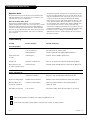
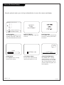
On-Screen Menus Overview
ON-SCREEN MENUS
Setup Menu Adjusts the basic characteristics of the TV
Auto Program 11 Automatically finds and stores active channels to scroll through using Channel Up/Down.
Add/Del/Blnk 15 Manually choose which active channels will appear when using Channel Up/Down.
Channel Labels 16 Labels the channels with their network names (ABC, CBS, HBO, etc.) or create custom names.
Clock Set 17 Sets the time.
On/Off Timers 18 Set the timers to automatically turn the TV On/Off each day at the preset time(s).
Captions 19 Chooses the captioning or text option.
Language 20 Chooses the language the on-screen menus will appear in.
Video Menu 21 Adjusts the picture appearance. The options are: Contrast, Brightness, Color, Tint, Sharpness,
Picture Pref.
FM Radio Menu 22 Adjusts the FM Radio options.
Parental Control 24 Allows installer to restrict viewable programming for up to 99 hours, with the use
of a password.
26 OTHER MENUS AND ON-SCREEN DISPLAYS
Channel/Time Shows the current time, selected channel and XDS* data if available.
Sleep Timer Sets the time the TV will turn off.
Volume Shows current sound level.
Captions Sets Caption/Text options.
Ch Preview Displays the available channels list.
Channel Bank Shows currently selected channel bank.
Inactive TV Prompts the patient to arrange for TV service.
INSTALLER MENUS 30 Sets up the TV’s operating features.
*XDS (Extended Data Service) Additional program information provided at the
discretion of the broadcaster. May include: title of broadcast, length of broadcast, and time
remaining until end of broadcast.
Descriptions of the menus on the TV
Using the Menu button on the optional installer’s remote, the installer can access all the menus below.
Menu Name Page Description

PAGE 15
NOAUX3684
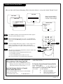
Fine-tune the patient’s channel selection list
Setting Add/Delete/Blank
Press the MENU key on the optional Installer’s remote to
show the Setup menu on the screen.
Press SELECT repeatedly to highlight the Add/Del/Blnk
option.
Using either the NUMBER keypad and ENTER or the
Channel Up/Down arrows on the remote, select a channel.
(If adding a deleted channel, you will need to use the
number keypad and ENTER.)
Using the Right/Left ADJ arrow, choose whether the chan-
nel is Added, Deleted, or Blank.
To continue, select another channel and repeat Step 3.
When you are finished, press ENTER to remove menu.
Adding VCR 3, VCR 4, or FM to the Channel
Preview List
Go to the Setup menu, select the Add/Del/Blnk option.
Use Channel Up/Down to select the option and choose
Added.
Note: If the option was turned off in the Service menu,
you will have to reinstate it before it can appear as an
option in the Channel Preview list.
Note: You can elect to Add, Delete or Blank: VCR 3 and
VCR 4. FM can be Added or Deleted, but not Blanked.
1
2
3
4
5
123
456
7
0
8
ENTER
9
POWER
TV/FM
FLSHBK
MUTE
VOLUME
CHANNEL
MENU
ADJ ADJ
SELECT
TIMER
BANK
CH PREVIEW
BED 1
BED 2
CC
-
+
-
+
2
AUTO PROGRAM
ADD/DEL/BLNK
CH. LABELS
CLOCK SET
TIMER
CAPTIONS
LANGUAGE
CH 44 ADDED
SETUP MENU
Mini glossary
ADD Adds new channels to the list that the patient can scroll through when using the remote.
DELETE Removes channels for one reason or another from the list that the patient can scroll through.
BLANK Removes the video signal from a channel so the patient will only receive the audio signal.
4
3/5
1
If you delete a channel, it isn’t gone for good. Just select it using
the NUMBER keypad on the remote, or add it later.
3
3

PAGE 16
206-3491-O
Setting Up Channel Labels
123
456
7
0
8
ENTER
9
POWER
TV/FM
FLSHBK
MUTE
VOLUME
CHANNEL
MENU
ADJ ADJ
SELECT
TIMER
BANK
CH PREVIEW
BED 1
BED 2
CC
-
+
-
+
AUTO PROGRAM
ADD/DEL/BLNK
CH. LABELS
CLOCK SET
TIMER
CAPTIONS
LANGUAGE
CH 32 ABC
SETUP MENU
Overview
Channel Labels help the user identify the channel or network being viewed.
In the Setup menu with the CH LABELS option highlighted, use the Adjust
Left/Right arrows to scroll through the available channel labels, such as,
A & E, AMC, ESPN, HBO, etc. These are a series of alphabetically organized preset
labels from which you can choose the more common networks. Use any of these
or create custom labels.
- - - - , The 4 dashes will allow a channel label to appear; if one is provided by
XDS. (Extended Data Service)
NONE, prevents any channel label from appearing.
LAB 1, thru LAB 20, are the 20 programmable labels.
The 20 programmable labels can be customized for your needs.
Each programmable label has 5 characters spaces available.
To Program a Channel Label
First select a channel using the NUMBER keypad and ENTER or the Channel
Up/Down arrows, on the optional Installer’s remote control.
(To select a deleted channel, use the NUMBER keypad and ENTER.)
To program a channel label, go to the Setup menu and select CH LABELS.
Press the Right/Left adjust arrow to scroll the available preset labels. Scroll past -
- - -, scroll past NONE, to go to the first programmable label slot, LAB 1. Notice
that the label appears with the title LAB 1, and is also on a dark background;
which will distinguish it from the preset labels.
Operating the Menu
Use Volume Up/Down to select the first letter.
Press MUTE to clear the label if necessary.
Use Channel Up/Down to change the character to one of the 255 characters avail-
able. (A blank letter space is available if required, after the “!” symbol.)
Adjust Left/Right Switches to the next label.
- - moves to the next or previous
label.
Volume Up/Down Selects character spaces
- - moves to the next or previous
character space.
Channel Up/Down Scrolls through the available
characters.
ENTER Accept the channel label and
removes the menu.
MUTE Removes current label,
- - if first character space is selected.

Mini glossary
TIME A four-digit figure broken down into hours and minutes, used to enter the current time when setting the clock or wake-up alarm.
HOURS First two digits that are entered when setting the clock or the wake-up alarm.
MINUTES The last two digits that are entered when setting the clock, or the wake-up alarm.
TIMER Chooses AM or PM when setting the clock.
PAGE 17
206-3747
The clock can also be set using 24 hour “military time.” For p.m. settings
add 1200. For example, to set 6:30 p.m., add 1200 to 630, = enter 1830.
For Auto Clock Set to work, TV must be tuned to a channel that has XDS
data available. Auto Clock Set, sets the time only once while the TV is on.
To set the clock with XDS data, turn TV off, then back on again, or set the
clock time manually.
Clock Set
123
456
7
0
8
ENTER
9
MENU
ADJ ADJ
SELECT
TIMER
BANK
CH PREVIEW
BED 1
BED 2
3
5
3
4
AUTO
EASTERN
CENTRAL
MOUNTAIN
PACIFIC
CLOCK MENU
CLOCK SET
TIME ZONE
DAY. SAVING
PRESS SELECT TO CHOOSE
PRESS ADJ TO CHANGE
AUTO
AUTO
OFF
ON
10:43 AM
CLOCK MENU
CLOCK SET
TIME SET
PRESS SELECT TO CHOOSE
PRESS ADJ TO CHANGE
MANUAL
TIMER
AUTO PROGRAM
ADD/DEL/BLNK
CH. LABELS
CLOCK SET
TIMER
CAPTIONS
LANGUAGE
SETUP MENU
TO SET CLOCK
AUTO PROGRAM
ADD/DEL/BLNK
CH. LABELS
CLOCK SET
TIMER
CAPTIONS
LANGUAGE
SETUP MENU
TO SET CLOCK
Clock Auto/Manual Operating Modes Setup
Use MENU, SELECT, and ADJ Left/Right to choose the Clock menu and to
set up the clock menu options, with the optional Installer’s remote.
Clock Mode Auto: TV automatically sets the time.
Time Zone: User can choose the time zone or have the
TV set it automatically.
Day. Savings: User can choose to have daylight
savings adjust the clock time one hour, or have the TV
adjust it automatically.
Manual: User sets the time on the clock.
Use ENTER repeatedly to remove menus.
2
1

PAGE 18
206-3747
123
456
7
0
8
ENTER
9
POWER
TV/FM
FLSHBK
MUTE
VOLUME
CHANNEL
MENU
ADJ ADJ
SELECT
TIMER
BANK
CH PREVIEW
BED 1
BED 2
CC
-
+
-
+
Set up On/Off Timers
Note: On/Off Timers
operate independently of
each other.
On the optional HP602 Installer’s remote, press MENU
repeatedly until the Setup menu appears.
Press SELECT repeatedly to highlight the Timer option, press
the Right arrow.
Use SELECT to choose an option. Use the number keypad
and/or the Left/Right ADJ arrows to enter the times. To set
PM, add 12 to the hours. For example, to set 6:00 p.m. Use
the number keypad to set 1-8-0-0. (6 for the hours and the
extra 12 for PM.) Do not use the TIMER key to set AM/PM.
Press ENTER to remove menu and return to TV viewing.
Your options are:
• On Time
Sets a time that the TV will turn itself On each day.
• Off Time
Sets a time that the TV will turn itself Off each day.
• On/Off Timer
Enables or disables the On/Off Timer functions. (The On/Off
Timer can be disabled but the settings will be retained.)
AUTO PROGRAM
ADD/DEL/BLNK
CH. LABELS
CLOCK SET
TIMER
CAPTIONS
LANGUAGE
TO SET TIMER
SETUP MENU
The clock must be set before the Timers will function.
The Off Timer can be used to turn the TV off at the preset time.
Note: No On Timer setting is required to use the Off Timer feature.
Mini glossary
TIME A four-digit figure broken down into hours and minutes, used to enter the time when setting the clock or programming timers.
HOURS First two digits that are entered when setting the clock or programming timers. (Add 12 for PM settings.)
MINUTES The last two digits that are entered when setting the clock, or programming timers.
ON TIME 9:00 AM
OFF TIME 7:00 PM
ON/OFF TIMER
ON
TIMER
Setting On/Off Timers
2
1
4
1
2
3
4
2/3
3
3

PAGE 19
206-3747
Standard closed captioning is available using the Caption 1 option.
Captions (Captions/Text)
CAPTION 1
CAPTION 2
CAPTION 3
CAPTION 4
TEXT 1
TEXT 2
TEXT 3
TEXT 4
OFF
CAPTIONS SETUP
OPER. MODE
SEL. TYPE
CAPTION LOCK
CC
CC
PRESS SELECT TO CHOOSE
PRESS ADJ TO CHANGE
STANDARD
ON, OFF
CC
CAPTION 1
CAPTION 2
CAPTION 3
CAPTION 4
TEXT 1
TEXT 2
TEXT 3
TEXT 4
TO SET CAPTIONS
CAPTIONS SETUP
OPER. MODE
SEL. TYPE
CAPTION
ON MUTE
CAPTION LOCK
CC
PRESS SELECT TO CHOOSE
PRESS ADJ TO CHANGE
QUICK/MUTE
ON, OFF
ON, OFF
ON, OFF
AUTO PROGRAM
ADD/DEL/BLNK
CH. LABELS
CLOCK SET
TIMER
CAPTIONS
LANGUAGE
SETUP MENU
TO SET CAPTIONS
AUTO PROGRAM
ADD/DEL/BLNK
CH. LABELS
CLOCK SET
TIMER
CAPTIONS
LANGUAGE
SETUP MENU
123
456
7
0
8
ENTER
9
POWER
TV/FM
FLSHBK
MUTE
VOLUME
CHANNEL
MENU
ADJ ADJ
SELECT
TIMER
BANK
CH PREVIEW
BED 1
BED 2
CC
-
+
-
+
1
2
Mini glossary
CAPTIONS The term for the words that scroll across the bottom of your TV screen; usually the audio portion of the program
provided for the hearing impaired.
TEXT The term for the words that appear in a large black frame and almost cover the entire screen; usually messages
provided by the broadcaste
r.
Set up Closed Caption/Text options for the user
Closed Captions/Text Operating Modes Setup
Use MENU, SELECT, and ADJ Left/Right to choose the Closed Captions/Text
mode and to set up the other menu options for the user with the optional
Installer’s remote.
Quick/Mute When CC is pressed: User can only turn Captions on/off.
(If CC on Mute is on, shows captions option on mute.)
(If locked, type is retained with Power on/off.)
Standard When CC is pressed: User can choose a captions type.
(If locked, type is retained with Power on/off.)
Press ENTER repeatedly to remove menus.
Caption/Text are features which allow the Concierge TV to receive the closed
caption and/or text options if made available by the broadcaster.
Availability and functionality of Caption/Text options are determined only by each
broadcaster and may not be available in your area.

PAGE 20
206-3491-O
Language
AUTO PROGRAM
ADD/DEL/BLNK
CH. LABELS
CLOCK SET
TIMER
CAPTIONS
LANGUAGE
ENGLISH
SETUP MENU
123
456
7
0
8
ENTER
9
POWER
TV/FM
FLSHBK
MUTE
VOLUME
CHANNEL
MENU
ADJ ADJ
SELECT
TIMER
BANK
CH PREVIEW
BED 1
BED 2
CC
-
+
-
+
2
1
4
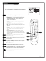
Choose the language for the on-screen menus
Press the MENU key on the optional Installer’s remote
control so the Setup menu appears.
Use the SELECT key on the remote control, to highlight
Language on the screen.
Press the Right/Left ADJ arrow to choose one of the
following options: English, Spanish or French.
Press ENTER to return to TV viewing.
1
2
3
4
3
La pagina si sta caricando...
La pagina si sta caricando...
La pagina si sta caricando...
La pagina si sta caricando...
La pagina si sta caricando...
La pagina si sta caricando...
La pagina si sta caricando...
La pagina si sta caricando...
La pagina si sta caricando...
La pagina si sta caricando...
La pagina si sta caricando...
La pagina si sta caricando...
La pagina si sta caricando...
La pagina si sta caricando...
La pagina si sta caricando...
La pagina si sta caricando...
La pagina si sta caricando...
La pagina si sta caricando...
La pagina si sta caricando...
La pagina si sta caricando...
La pagina si sta caricando...
La pagina si sta caricando...
La pagina si sta caricando...
La pagina si sta caricando...
La pagina si sta caricando...
La pagina si sta caricando...
La pagina si sta caricando...
La pagina si sta caricando...
-
 1
1
-
 2
2
-
 3
3
-
 4
4
-
 5
5
-
 6
6
-
 7
7
-
 8
8
-
 9
9
-
 10
10
-
 11
11
-
 12
12
-
 13
13
-
 14
14
-
 15
15
-
 16
16
-
 17
17
-
 18
18
-
 19
19
-
 20
20
-
 21
21
-
 22
22
-
 23
23
-
 24
24
-
 25
25
-
 26
26
-
 27
27
-
 28
28
-
 29
29
-
 30
30
-
 31
31
-
 32
32
-
 33
33
-
 34
34
-
 35
35
-
 36
36
-
 37
37
-
 38
38
-
 39
39
-
 40
40
-
 41
41
-
 42
42
-
 43
43
-
 44
44
-
 45
45
-
 46
46
-
 47
47
-
 48
48


in altre lingue
- English: LG H20F50DT Owner's manual
Altri documenti
-
Zenith HealthView H20E50DT Installation And Operating Manual, Warranty
-
-
-
Funai WF-13 Manuale utente
-
-
Zenith Concierge H25C39Y Installation And Operating Manual, Warranty
-
-
-
-
Aria A1260R Instructions Manual