
GCE VALVES
INSTRUCTION FOR USE:
PRESSURE REGULATORS INTEGRATED WITH CYLINDER VALVES
BEDIENUNGSANLEITUNG:
DRUCKREGLER MIT FLASCHENVENTILEN
MODE D‘EMPLOI:
DETENDEURS INTEGRES
GEBRUIKSAANWIJZING:
REDUCEERVENTIELEN MET GEINTEGREERDE CILINDER AFSLUITERS
INSTRUCCIONES DE USO: REGULADORES DE PRESIÓN INTEGRADOS CON
VÁLVULAS DE BOTELLA
INSTRUÇÕES DE UTILIZAÇÃO: REGULADORES DE PRESSÃO INTEGRADOS EM
VALVULAS DE GARRAFAS
ISTRUZIONI D´USO: RIDUTTORE DI PRESSIONE INTEGRATO CON VALVOLE PER
BOMBOLA
HASZNÁLATI ÚTMUTATÓ:
NYOMÁSCSŐKKENTŐVEL INTEGRÁLT PALACKSZELEPEK
NÁVOD K POUŽITÍ: REGULÁTORY TLAKU S INTEGROVANÝM UZAVÍRACÍM
VENTILEM PLYNOVÝCH LAHVÍ
INSTRUKCJA OBSŁUGI:
ZINTEGROWANY ZAWÓR BUTLOWY
ANVÄNDARANVISNING:
TRYCKREGULATORER INTEGRERAS MED GASFLASKVENTILER
BRUKSANVISNING:
TRYKKREGULATORER INTEGRERT MED SYLINDERVENTILER
BRUGERVEJLEDNING:
TRYKREGULATORER INTEGRERET MED FLASKEVENTILER
KÄYTTÖOHJE:
PAINEENSÄÄTIMET INTEGROITU VENTTIILIT
ΟΔΗΓΙΕΣ ΧΡΗΣΗΣ:
ΡΥΘΜΙΣΤΕΣ ΠΙΕΣΗΣ ΕΝΣΩΜΑΤΩΜΕΝΟΙ ΣΤΙΣ ΒΑΛΒΙΔΕΣ ΦΙΑΛΗΣ
使用说明:
集成气瓶阀的压力调节器
NÁVOD NA POUŽITIE: REGULÁTORY TLAKU S INTEGROVANÝM UZATVÁRACÍM
VENTILOM PLYNOVÝCH FLIAŠ
KASUTUSJUHEND:
ÕHUREGULAATORID SISSEEHITATUD RÕHUVENTIILIDEGA
LIETOŠANAS PAMĀCĪBA:
SPIEDIENA REGULATORI AR INTEGRĒTU GĀZES BALONU SLĒGVĀRSTU
NAUDOJIMO INSTRUKCIJA:
SLĖGIO REGULIATORIAI SU INTEGRUOTU DUJŲ BALIONŲ UŽDARYMO VOŽTUVU
NAVODILO ZA UPORABO:
REGULATORJI PRITISKA Z VGRAJENIM ZAPORNIM VENTILOM ZA JEKLENKE S
PLINOM
UPUTSTVA ZA UPOTREBU:
REGULATORI PRITISKA SA INTEGRISANIM ZAPORNIM VENTILOM ZA GASNE BOCE
UPUTE ZA UPORABU:
REGULATORI TLAKA S INTEGRIRANIM ZAPORNIM VENTIOM ZA PLINSKE BOCE
INSTRUCȚIUNI DE UTILIZARE:
REGULATOARE DE PRESIUNE CU VENTIL DE ÎNCHIDERE A BUTELIILOR INTEGRAT
ИНСТРУКЦИЯ ПО ПРИМЕНЕНИЮ:
РЕГУЛЯТОРЫ ДАВЛЕНИЯ, ИНТЕГРИРОВАННЫЕ С БАЛЛОННЫМИ ВЕНТИЛЯМИ
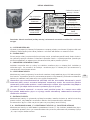
MediVital®
EN
RU
DE
FR
NL
ES
PT
IT
HU
CS
PL
SV
NO
DA
FI
EL
ZH
SK
ET
LV
LT
SL
SR
HR
RO

EN PAGE: 3 - 11
DE SEITE: 12 - 21
FR PAGE : 22 - 31
NL PAGINA: 32 - 40
ES PÁGINA: 41 - 50
PT PÁGINA: 51 - 60
IT PAGINA: 61 - 70
HU ÁRUK: 71 - 80
CS STRANA: 81 - 89
PL STRONA: 90 - 99
SV SIDA: 100 - 108
NO SIDE: 109- 117
MediVital®
DA SIDE: 118 - 126
FI SIVU: 127 - 135
EL ΣΕΛΙΔΑ: 136 - 145
CN 页面 : 146 - 153
SK STRANKA: 154 - 162
ET PAGE: 163 - 171
LV PAGE: 172- 180
LT LAPPUSE: 181 - 189
SL STRAN: 190 - 198
SR CTPAHA: 199 - 207
HR STRANICA: 208 - 216
RO PAGINĂ: 217 - 226
RU PAGINĂ: 227 - 236

3/239
EN
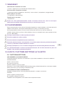
1. FOREWORD
The product complies with the essential requirements of 93/42/EEC Medical Device Directive,
Transportable Pressure Equipment Directive 2010/35 EU and CDG TPE (Amendment) & (EU
Exit) Regulations 2020. The combination valve is designed according to EN ISO 10524-3 and
EN ISO 10297 standards.
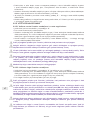
2. INTENDED USE
MediVital® Combination Valves are designed to be fitted to gas cylinders used for medical
gases. These combination valves together with a gas cylinder form gas packages used either
as gas supply point for medical devices (anaesthetic devices, ventilating devices, incubators
etc.) or for direct gas supply to a patient’s breathing mask or cannula.
GCE Combination Valves are intended to be used with the following medical gases:
• Oxygen
• Nitrous oxide
• Air for breathing
MediVital® combination valve is not intended for use with flammable anaesthetics and
substances.
2.1. PATIENT PROFILE
Medivital® supplies medical gas by means of the control flow head in flow range from 0 to 15
(25) l/min. Saturation of the medical gas must be prescribed by the doctor or an anaesthetic
nurse who has got the medical education, assessed the heath status of the patient and supplies
him with required amount of the medical gas.
Health status - the assesment and decision about the use timing and dosage amount
requirements of the patient is up to the doctor or medical personnel.
Medical personnel - nurse, rescuer, paramedic or carer who has obtained medical education.
2.2. USER PROFILE
Use in the hospital or ambulance:
• Education: personnel with medical education
Home care use:
Therapy is prescribed by a doctor or personnel who has got a medical education in the field of
breathing support:
• Knowledge: training of personnel with medical education who has got an ability to read, train
and apply knowledge from the instruction for use.
Training must be performed according to regulations valid in each country.
Important:
Patient must be trained by the doctor or person who has got an education in the life saving.
3. OPERATIONAL, TRANSPORT AND STORAGE SAFETY
REQUIREMENTS
KEEP THE PRODUCT AND ITS ASSOCIATED EQUIPMENT AWAY FROM:
• Heat sources (fire, cigarettes,...)
• Flammable materials
• Oil or grease (take a great care in the use of hand creams)
• Water
ENGLISH
INSTRUCTION FOR USE: MEDIVITAL®
• Helium
• Carbon dioxide
• Mixtures of the gases listed above

4/239
EN
• Dust
The product and its associated equipment must be prevented from tipping over, turning over
or falling.
Always maintain oxygen cleanliness standards.
Only use the product and its associated equipment in well ventilated area.
Before the first use the product shall be kept in its original package. If removed from service
(for transport, storage) GCE recommends using the original package (including inner packing
materials).
National laws, rules and regulations for medical gases, accident prevention and environmental
protection must be observed.
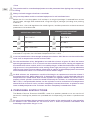
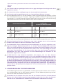
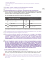
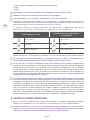
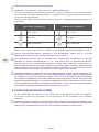
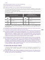
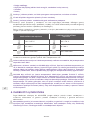
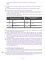
OPERATING CONDITIONS STORAGE AND TRANSPORT
CONDITIONS
-20* / +65 °C -40 / +70 °C
10 / 100 % 10 / 100 %
600 / 1200 mbar 600 / 1200 mbar
*for inner tightness of the shut-o valve, during transport and storage of the combination valve
mounted on a cylinder, the valid lower temperature limit is -40°C.
In case of combination valve storage at temperature below -20°C do not use the combination
valve until its temperature reaches at least -20°C.
For the combination valves designed to be used with mixture of gases O2+N2O, the lowest
operating temperature is +5°C. In normal use of the combination valve, frosting can appear on
the combination valve surface, which is caused by the gas inside the combination valve when
high pressure in the combination valve cooling when high pressure gas is being reduced to
low pressure (Joule-Thomson eect). Check that all patient associated equipment connected
to the combination valve is via a hose of at least 2 metres length.
O2+N2O mixtures are temperature sensitive. N2O begins to separate out from the mixture if
the temperature falls below about -6°C. A homogenous mixture is again obtained when the
temperature has raised above 10°C and the cylinder was agitated. Before use, to ensure it is
properly mixed, cylinders should be stored horizontally for 24 hours at a temperature above
10°C. If this is not practicable, before use the cylinders must be maintained at a temperature
above 10°C for at least 2 hours and then completely inverted three times or placed in warm
water at body temperature for 5 minutes and then completely inverted three times.
4. PERSONNEL INSTRUCTIONS
The Medical Devices Directive 93/42/EEC states that product provider must ensure that all
personnel handling the product are provided with the operating instructions & performance
data.
Do not use the product without properly familiarization of the product and its safe operation
as defined in this Instruction for use. Ensure user is aware of particular information and
knowledge required for the gas in use.

5/239
EN
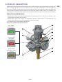
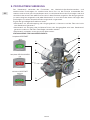
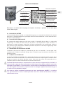
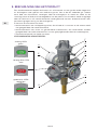
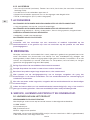
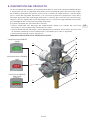
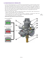
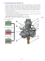
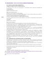
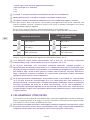
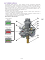
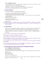
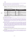
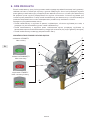
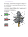
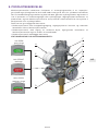
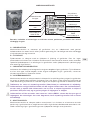
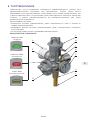
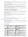
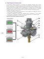
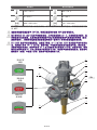
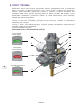
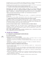
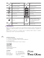
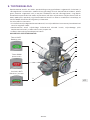
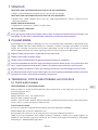
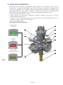
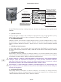
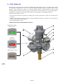
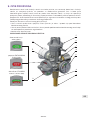
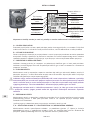
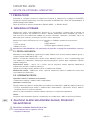
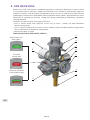
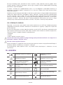
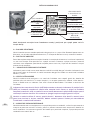
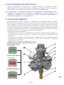
5. PRODUCT DESCRIPTION
Combination valve combines the function of shut-o valve of a high pressure gas cylinder and
pressure regulator for the use with medical gases. Gas from the cylinder is first controlled by
the main shut-o valve and then passed through the pressure regulator and finally delivered
to the patient through the flow outlet or the pressure outlet. Outlet pressure is fixed by the
manufacturer and each combination valve is provided with a low-pressure relief valve to protect
against pressure regulator failure.
There are three basic alternatives:
• combination valve with quick-coupler outlet, the outlet pressure is constant, and flow is not
controlled by the combination valve
• combination valve with outlet via calibrated nozzles, outlet flows is controlled by the
combination valve and can be changed by the control head,
• the combination valve of both alternatives.
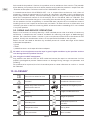
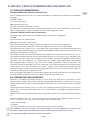
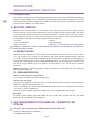
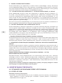
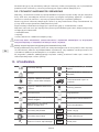
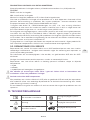
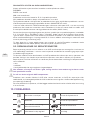
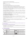
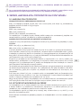
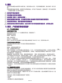
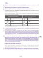
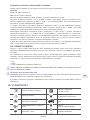
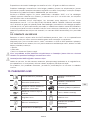
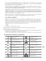
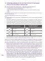
SHUT OFF VALVE STATUS INDICATOR:
fully OPEN
green colour
fully CLOSED
red colour
partly OPEN
red / green colour
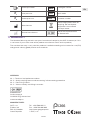
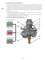
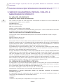
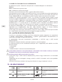
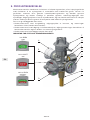
H
D
G
F
I
B
C
E
A
J

6/239
EN
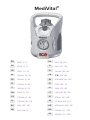
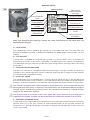
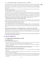
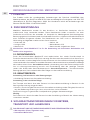
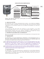
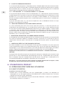
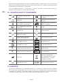
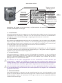
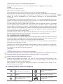
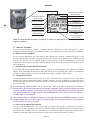
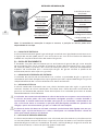
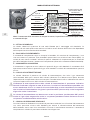
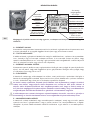
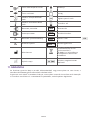
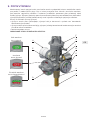
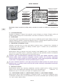
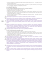
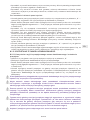
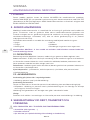
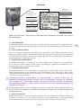
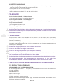
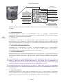
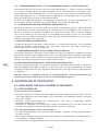
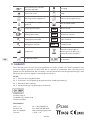
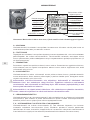
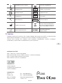
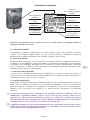
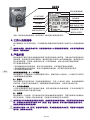
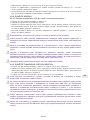
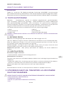
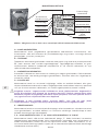
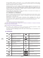
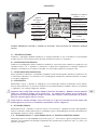
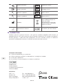
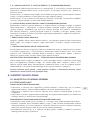
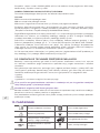
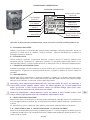
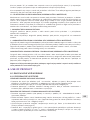
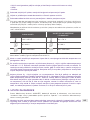
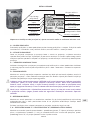
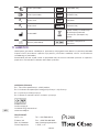
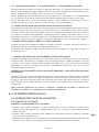
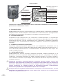
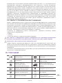
MARKING DETAIL
Note: The content of the marking is always the same, the position on the valve may vary
depending on the type.
A INLET STEM
The combination valve is fitted to gas cylinder by a threaded inlet stem. The inlet stem can
be taper threaded or parallel threaded with dierent size depending on the cylinder size and
material.
B FILLING PORT
A filling port is provided for filling the gas cylinder at a filling station, it has no function for
patient use. It includes a non-return valve (NRV). The NRV means that special filling adaptors
are required to vent gas from the cylinder during the filling process (venting and/or vacuuming
of cylinders).
C INLET PRESSURE INDICATOR
Inlet pressure indicator is intended to indicate amount of gas in the gas cylinder. The pressure
indicator is of an active type which means it indicates amount of gas in the gas cylinder whether
the shut-o valve is opened or closed.
D SHUTOFF VALVE
The combination valve is provided with a shut-o valve to isolate the gas in the cylinder from
the rest of combination valve functions. It must be opened during cylinder filling and patient's
therapy. Part of the handwheel is an indicator showing open/close status of the shut-o valve.
The shut-o valve open/close status indicator is for guidance only. The shut-o valve may not
be fully o when OFF status is showing. Fully closed status has to be checked by ensuring the
shut-o valve is turned fully clockwise until a firm resistance to rotation is reached and gas
supply to the outlets has stopped.
The shut-o valve must not be used in the "partly ON" status because even though gas is
supplied to the outlets, the flow can be limited due to insuciently opened shut-o valve.
E RESIDUAL PRESSURE VALVE
Combination valve is equipped with a residual pressure valve with function to retain a minimum
positive pressure in the gas cylinder to avoid contamination of the cylinder content by
atmospheric air. During cylinder gas ventilation through the filling port the residual pressure
valve is by passed.
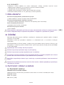
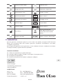
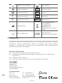
Marking detail
Inlet connection
type
Total weight
allowance of the
package
Filling port type
End of lifetime
Reference
number
Inlet pressure
Serial number
Compliance with
93/42/EEC
Compliance with
2010/35 EU
Additional
information
Compliance with CDG
TPE (Amendment) &
(EU Exit) Regulations
2020

7/239
EN
F, G FLOW CONTROL HEAD “F” AND FLOW OUTLET “G” OPTION
Combination valve can be delivered with a flow control head “F”.This function is used to supply
adjustable gas flow rates (l/min) at atmospheric pressure directly to a patient through the flow
outlet “G”, for instance through a cannula or a facemask. The flow outlet “G“ is equipped with
hose fitting (hose nipple) or a threaded type (for accessories to be connected via threaded
connection).
Movement of the flow outlet ‘G’ is normal due to the method of fixing in the main body. It doesn’t
indicate a faulty flow outlet.
H PRESSURE OUTLET OR QUICK COUPLER OPTION
The combination valve may be fitted with a pressure outlet. The pressure outlet is supplied with
gas direct from the low-pressure part of the combination valve and it is fitted with a gas specific
medical quick coupling connector also called “quick coupler”. The user can connect another
piece of equipment to this outlet with a gas specific male probe (see appendix nr. 2). The quick
coupler self seals when the male probe is disconnected. This outlet is for supplying gas at a
controlled pressure to power medical devices, for instance medical ventilator.
I PRESSURE RELIEVE VALVE OF LOW PRESSURE PART
Pressure relieve valve secures the low pressure part of combination valve and connected
medical devices against over-pressure. If the gas pressure is decreased enough after the
pressure relieve valve activation, it will closes itself.
J EXCESS FLOW DEVICE OR DIP TUBE OPTION
Excess flow device ensures safe ventilation of gas from gas cylinder in case the combination
valve is broken above inlet stem (e.g. cylinder fall). Dip tube does not have such function. Excess
flow device and dip tube are to avoid contamination from cylinder entering the combination
valve.
PRESSURE RELIEVE DEVICE OF HIGH PRESSURE PART BURSTING DISC OPTIONAL
The high pressure relieve device is intended to protect the cylinder and high pressure part
of combination valve against damage caused by increased cylinder pressure. If the pressure
relieve device has been activated, it will not reseal and the combination valve must be taken
out of service for repair (see Chapter 9).
Note: Colour of the product (especially guard, flow control head and shut-o valve) does not
have to match the gas colour coding.
6. USE OF PRODUCT
6.1. OPERATIONS PERFORMED BY USER
6.1.1. BEFORE USE
VISUAL INSPECTION BEFORE USE:
• Check the combination valve for damage (incl. label and marking). If it shows signs of external
damages, remove the product from service and suitably identify its status.
• Check the combination valve for contamination. If needed apply the cleaning procedure
according to chapter 8.
• Check that the cylinder gas pressure indicator indicates sucient pressure. If it indicates in
the red zone, return the cylinder with combination valve back for filling.
LEAKTIGHT AND FUNCTIONAL TEST BEFORE USE:
• Set flow control head (if any) on ZERO position - ensure the flow control head engages
correctly.
• Slowly open shut-o valve handwheel (anticlockwise) until fully open - after approx. 1 turn (see
indication in picture chapter 5).
• By listening check for leakage (leakage would be heard as characteristic hiss of flowing gas).
• Check that there is a gas flow at each flow control head set position in both clockwise and
anticlockwise turning direction (for instance by sound or checking presence of bubbles in a
humidifier).

8/239
EN
• Close the shut-o valve (clockwise). Do not use excessive torque (max. closing torque is 5
Nm).
• Reset flow control head to ZERO position and ensure flow control head engages correctly.
• For combination valve fitted with pressure outlet, ensure it is in working condition by
connecting and disconnecting quick-coupler probe.
6.1.2. USE OF COMBINATION VALVE
6.1.2.1. Use of combination valve flow outlet and setting of flow:
• Ensure the flow control head is in position “0”.
• Connect accessories to the flow outlet.
• Slowly open shut-o valve handwheel (anticlockwise) until fully open - after approx. 1 turn (see
indication in picture chapter 5).
• Set flow head to required flow position. Ensure flow control head engages correctly.
Before connecting any accessory to the flow outlet make sure that the patient is not connected.
Sudden opening could result in a danger of fire or explosion arising from oxygen pressure
shocks. Insucient opening of the shut-o valve could reduce actual flow delivered.
Always ensure that the flow control head has been correctly set and not placed between two
settings. Flow control head placed between settings will not deliver correct flow of medical
gas.
Common variants of flow control head can have an “end stop” in between the maximum flow
position and the zero position. Do not try to apply excessive force on the flow control head
when it stops in the maximum flow position (during clockwise rotation) or in zero position
(anti-clockwise rotation).
Medical gas flow rate must be prescribed by a doctor.
6.1.2.2. Use of combination valve pressure outlet
• Ensure the flow control head is in position “0” (if included).
• Slowly open shut-o valve handwheel (anticlockwise) until fully open - after approx. 1 turn (see
indication in picture chapter 5).
• Connect accessory to the pressure outlet if not already connected.
Before connecting any accessory to the pressure outlet make sure that the patient is not
connected and the accessory outlet is secured.
If pressure outlet is to be connected to a medical device that requires high gas flow (for
instance pulmonary ventilator that requires gas flow 100 l/min at the minimum pressure
2.8 bar), compare the required flow of connecting medical device with pressure and flow
characteristics of the combination valve stated in appendix Nr. 1. To assure sucient
performance (pressure and flow characteristics of the combination valve ) the medical device
should not be used if pressure indicator enters the red zone.
Sudden opening could result in a danger of fire or explosion arising from oxygen pressure
shocks. Insucient opening of the shut-o valve could reduce actual flow delivered.
If a pressure outlet as well as a flow outlet are part of the combination valve do not use them
simultaneously, especially if pressure in the cylinder is below 50 bar, in could adversely aect
the outlet parameters of the combination valve.
6.1.3. AFTER USE
• Close shut-o valve (clockwise). Do not use excessive torque(max. closing torque is 5 Nm).
• Vent pressure from the connected devices.
• Disconnect all connected devices from user outlets.
• Set flow control head on "0" (if included).

9/239
EN
7. ACCESSORIES
ACCESSORIES CONNECTABLE TO FLOW OUTLET:
• hose connected with mask, cannula or humidifier.
ACCESSORIES CONNECTABLE TO PRESSURE OUTLET:
• low pressure hose (working pressure >10 bar), flowmeters, Venturi suction ejectors, lung
ventilators.
OTHER USER ACCESSORIES:
• bed hanger, humidifier holder.
ACCESSORIES FOR FILLING STATIONS:
• filling adaptor.
Before connecting any accessory or medical device to the combination valve, always check
that they are fully compatible with connection features & performances of the product.
8. CLEANING
Remove dirt with a soft cloth damped in oil free soap water & rinsed with clean water.
Disinfection can be carried out with an alcohol-based solution (with damped wipes). If other
cleaning solutions are used, check that they are not abrasive and they are compatible with
the product materials (including labels) and gas (convenient cleaning solution - i.e. Meliseptol).
Do not use cleaning solutions containing ammonia!
Do not expose to water or any other liquid.
Do not expose to high temperature (such as autoclave).
To apply the cleaning solution do not spray it as the spray may enter into the inner parts of
combination valve and cause contamination or damage.
Do not use pressure wash as it could damage or contaminate the combination valve.
If the inner parts of the combination valve have been contaminated do not continue to use the
combination valve under any circumstances. It must be withdrawn from service.
9. SERVICE, PRODUCT LIFE TIME AND MAINTENANCE
9.1. PRODUCT LIFE TIME
SERIAL NUMBER AND MANUFACTURE DATE
An eleven-figure serial number stamped on combination valve body consists of the data as
follows:
YYYYMM XXXXX
YYYY: year of manufacture
MM: month of manufacture
XXXXX: sequence number of product
For example: Serial number 201303 00521 indicates the combination valve manufactured in
2013, in March, with sequence number 521.
PRODUCT LIFE TIME AND WASTE MANAGEMENT
End of life time is marked on the combination valve body this way:
YYYYMM
YYYY: year of lifetime end
MM: month of lifetime end
Maximum life time of this product is 15 years from date of manufacturing.

10/239
EN
At the end of the product’s life time, the product must be withdrawn from service. The provider
of the device shall prevent the reuse of the product and handle the product in compliance with
“Directive of European Parliament and Council 2008/98/EC on waste“.
In accordance to Article 33 of REACH GCE, s.r.o. as responsible manufacturer shall inform all
customers if materials containing 0.1% or more of substances included in the list of Substance
of Very High Concern (SVHC). The most commonly used brass alloys used for valve bodies and
other brass components contain 2-3% of lead (Pb), EC no. 231-468-6, CAS no. 7439-92-1. The
lead will not be released to the gas or surrounding environment during normal use. After end of
life the product shall be scrapped by an authorized metal recycler to ensure ecient material
handling with minimal impact to environment and health. To date we have no information that
indicates that other materials containing SVHC of concentrations exceeding 0.1% are included
in any GCE product.
9.2. REPAIR AND SERVICE OPERATIONS
Repairs and service can be only done by a GCE certified person who also holds all necessary
certificates in compliance with national standards for mounting and repair of dedicated gas
devices. For information about a service in your area please contact GCE or distributor of GCE
product. Usually the combination valves can be repaired while fitted on the cylinder.
Repair that do not need to be done by certified personnel include exchange of the below
mentioned components:
• guard,
• labels,
• protective covers and separable hose adaptors.
All labels on the equipment must be kept in good, legible condition by the provider and the
user during the entire product life time.
Use only genuine GCE components.
Any product sent back to GCE (or GCE authorised centre) for repair or maintenance shall be
properly packaged to prevent contamination or damage during storage, transportation and
handling.
For product to be repaired, the fault short description or some reference to a claim nr. should
be indicated.
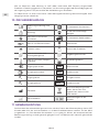
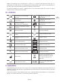
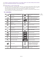
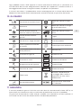
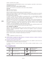
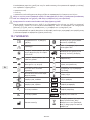
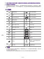
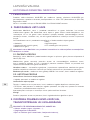
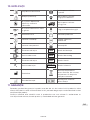
10. GLOSSARY
Consult instruction for use Suitable for Hospital care use
Caution! Suitable for Home care use
Keep away from heat and
flammable materials
Suitable for Emergency care
use
Keep away from oil and
grease! Fragile, handle with care
Keep dry! Weight of product
Humidity limit Atmospheric pressure
limitation
Temperature limit Use by date
Inlet parameter SN Serial number

11/239
EN
Outlet parameter REF Catalogue number
P1Inlet pressure LOT Batch code
P2Outlet pressure REF 1 Customer number
Manufacturer
Take the equipment back for
recycling. Do not dispose
equipment into unsorted
municipal waste.
Date of manufacture Authorised representative
for Switzerland
11. WARRANTY
The Standard Warranty period is two years from date of receipt by the GCE Customer (or if this
is not known 2 years from time of the product manufacture shown on the product).
The standard warranty is only valid for products handled according to Instruction for use (IFU)
and general industry good practice and standards.
APPENDIX:
Nr. 1 – Technical and performance data
Nr. 2 – Quick coupling feature and connecting / disconnecting procedure
Nr. 3 – Post Filling Checks
Nr. 4 – Valve assembly and fi lling instruction
MANUFACTURER:
GCE, s.r.o. Tel : +420 569 661 111
Zizkova 381 Fax : +420 569 661 602
583 01 Chotebor http://www.gcegroup.com
Czech Republic © GCE, s.r.o.
EUMEDIQ AG
Grafenauweg 8
CH-6300 Zug, Switzerland
www.eumediq.eu
1266

12/239
DE 1. VORWORT
Das Produkt erfüllt die grundlegenden Anforderungen der Richtlinie 93/42/EWG über
Medizinprodukte, der Richtlinie 2010/35 EU über ortsbewegliche Druckgeräte und CDG TPE
(Amendment) & (EU Exit) Regulations 2020. Das Kombiventil erfüllt die Anforderungen der
Normen EN ISO 10524-3 und EN ISO 10297.
2. ZWECKBESTIMMUNG
MediVital® Kombiventile wurden für den Anschluss an Gasflaschen konzipiert, die für
medizinische Gase verwendet werden. Diese Kombiventile bilden zusammen mit einer
Gasflasche eine Einheit, die entweder als Gasquelle für Medizingeräte (Anästhesiegeräte,
Beatmungsgeräte, Inkubatoren) oder für die direkte Gaszufuhr zur Atemmaske oder Nasenbrille
eines Patienten eingesetzt werden. Die Kombiventile von GCE sind zur Verwendung in
Verbindung mit folgenden medizinischen Gasen bestimmt:
• Sauersto, O2
• Lachgas, N2O
• Atemluft, Air
Kombiniertes Ventil MediVital®E ist für die Anwendung mit brennbaren Anästhetika und
Stoen nicht vorgesehen.
2.1. PATIENTENPROFIL
Durch den Druckminderer Medivital®E wird medizinisches Gas mittels Durchflusskopf im
Durchflussbereich von 0 bis 15 (25) l/min versorgt. Die Saturation des medizinischen Gases muss
durch Arzt oder anästhesiologische Krankenschwester mit Gesundheitsausbildung festgelegt,
sie beurteilen den Gesundheitszustand des Patienten und verabreichen eine erforderliche Menge
des medizinischen Gases. Gesundheitszustand – Anwendung, wenn der Patient medizinisches
Gas als Atmungsunterstützung braucht und Entscheidung über die jeweilige Therapie
seitens des Arztes oder Gesundheitspersonals. Gesundheitspersonal – Krankenschwester,
Rettungspersonal, Gesundheitshelfer oder Pfleger mit Gesundheitsausbildung.
2.2. BENUTZERPROFIL
Anwendung im Krankenhaus oder Rettungswagen:
• Ausbildung: Personal mit Gesundheitsausbildung
Anwendung in der häuslichen Pflege:
Die Therapie wird durch Arzt oder Personal mit Gesundheitsausbildung im Bereich für die
Atmungsunterstützung vorgeschrieben:
• Kenntnis: Einschulung des Personals mit Gesundheitsausbildung mit der Fähigkeit, Kenntnisse
von der Bedienungsanleitung zu lesen, einzuschulen und anzuwenden
Die Einschulung muss gemäß den landspezifischen gültigen Gesetzen erfolgen.
Wichtig:
Der Patient muss durch Arzt oder Personal mit der Ausbildung im Bereich der Lebensrettung
unterwiesen werden.
3. SICHERHEITSANFORDERUNGEN FÜR BETRIEB,
TRANSPORT UND LAGERUNGS
DAS PRODUKT UND DIE ZUGEHÖRIGEN GERÄTE SIND FERNZUHALTEN VON:
• Wärmequellen (Feuer, Zigaretten usw.),
• brennbaren Materialien,
DEUTSCH
BEDIENUNGSANLEITUNG: MEDIVITAL®
• Helium, He
• Kohlendioxid, CO2
• Gemische der aufgeführten Gase

13/239
DE
• Ölen oder Fetten, (besondere Vorsicht: keine Handcreme verwenden,
• Wasser,
• Staub.
Das Produkt und die zugehörigen Geräte müssen gegen Umkippen, Umschlagen oder Sturz
abgesichert werden.
Es sind alle Vorschriften und Regelungen zur Sauerstoreinheit einzuhalten.
Das Produkt und die zugehörigen Geräte nur in gut gelüfteten Räumen einsetzen.
Vor Erstinbetriebnahme muss sich das Produkt in seiner Originalverpackung befinden. Im Falle
der Außerbetriebsetzung (für Transport, Lagerung) empfiehlt GCE die Originalverpackung
anzuwenden. Es sind die nationalen Gesetze, Regelungen und Vorschriften zu Unfallverhütung
und Umweltschutz beim Einsatz von medizinischen Gasen zu beachten.
ARBEITSBEDINGUNGEN LAGER UND
TRANSPORTBEDINGUNGEN
-20°C* / +65°C -40°C / +70°C
10 / 100 % 10 / 100 %
600 / 1200 mbar 600 / 1200 mbar
*um die innere Dichtigkeit des Absperrventils sicherzustellen, gilt bei Transport und Lagerung
des an einer Flasche montierten Kombiventils ein unterer Temperaturgrenzwert von -40 °C.
Wird das Kombiventil bei einer Temperatur unter -20 °C gelagert, darf es nicht verwendet
werden bevor wieder ein Wert von mindestens -20 °C erreicht.
Für Kombiventile, die zur Verwendung mit einem Mischgas aus O2+N2O vorgesehen sind,
liegt die niedrigste Betriebstemperatur bei +5 °C. Beim bestimmungsgemäßen Gebrauch
kann sich auf der Oberfläche des Kombiventils eine leichte Frostschicht ablagern. Dies wird
dadurch verursacht, dass die Temperatur des Gases durch eine Drosselung des Drucks
sinkt (Joule-Thomson-Eekt). Es ist sicherzustellen, dass alle, den Patienten betreenden
Komponenten nur über einen Schlauch mit einer Mindestlänge von 2 Metern an das
Kombiventil angeschlossen werden.
O2+N2O-Gemische sind temperaturempfindlich. N2O beginnt sich aus dem Gemisch
abzutrennen, wenn die Temperatur unter ca. -6 °C fällt. Sobald die Temperatur wieder auf über
10 °C ansteigt und die Gasflasche gekippt wird, entsteht wieder ein homogenes Gemisch. Um
vor der Verwendung ein ordnungsgemäßes Mischen sicherzustellen, sollten die Flaschen für
die Dauer von 24 Stunden bei einer Temperatur von über 10 °C horizontal gelagert werden. Ist
dies nicht möglich, müssen die Gasflaschen vor der Verwendung entweder über mindestens
2 Stunden bei einer Temperatur von über 10 °C gelagert oder für die Dauer von 5 Minuten in
warmes Wasser (Körpertemperatur) eingetaucht und anschließend jeweils 3 Mal vollständig
gekippt werden.
4. ANWEISUNGEN FÜR MITARBEITER
Gemäß Medizingeräteverordnung 93/42/EWG, hat der Eigentümer des Produkts sicherzustellen,
dass alle Mitarbeiter, die mit dem Produkt umgehen, mit der Bedienungsanleitung und den
technischen Daten des Produkts vertraut sind.
Verwenden Sie das Produkt nicht, ohne dass Sie das Produkt und seinen sicheren Betrieb
kennen, wie in dieser Bedienungsanleitung angegeben. Stellen Sie sicher, dass der Benutzer
über die für das verwendete Gas erforderlichen Informationen und Kenntnisse verfügt.

14/239
DE
5. PRODUKTBESCHREIBUNG
Das Kombiventil verbindet die Funktionen von Hochdruck-Gasflaschenventilen und
medizinischen Druckreglern für medizinische Gase. Das aus der Flasche austretende Gas
strömt zunächst durch das Haupt-Absperrventil, anschließend durch den Druckregler und wird
schließlich über einen Flow- oder Druckanschluss dem Patienten zugeführt. Der Ausgangsdruck
ist werksseitig fest eingestellt und jedes Kombiventil ist zum Schutz bei einem Versagen des
Druckreglers mit einem Unterdruckentlastungsventil ausgestattet.
Es gibt drei grundlegende Produktvarianten:
• Kombiventil mit Schnellkupplung; der Ausgangsdruck ist konstant und der Flow wird nicht
vom Kombiventil gesteuert
• Kombiventil mit Ausgang über kalibrierte Düsen; der Ausgangsflow wird vom Kombiventil
gesteuert und kann über den Flow-Regler verändert werden
• Kombiventil mit beiden zuvor genannten Alternativen
STATUSANZEIGE FÜR DAS ABSPERRVENTIL:
komplett GEÖFFNET
grün
komplett GESCHLOSSEN
rot
teilweise GEÖFFNET
rot/grün
H
D
G
F
I
B
C
E
A
J

15/239
DE
EINZELHEITEN ZUR KENNZEICHNUNG
Hinweis: Der Inhalt der Markierung ist immer gleich. Die Platzierung am Produkt kann,
abhängig vom Typ, variieren.
A ANSCHLUSSSTUTZEN
Das Kombiventil wird mit einem Gewinde-Anschlussstutzen in die Gasflasche eingedreht.
Der Anschlussstutzen ist entweder mit einem konischen oder einem zylindrischen Gewinde
ausgestattet und in verschiedenen Größen (für verschiedene Flaschengrößen und -materialien)
erhältlich.
B FÜLLÖFFNUNG
A Die Füllönung dient dem Füllen der Gasflasche an einer Füllstation; sie hat keine
patientenrelevante Funktion. Sie ist mit einem Rückschlagventil (NRV) ausgestattet. Das
Rückschlagventil erfordert den Einsatz spezieller Fülladapter zum Entlüften der Flasche
während des Füllens (Entlüften und/oder Evakuieren der Gasflaschen).
C MANOMETER ZUR ANZEIGE DES FLASCHENINHALTS
Dies ist ein aktives Manometer das den Flascheninhalt bei geönetem und bei geschlossenem
Absperrventil anzeigt.
D ABSPERRVENTIL
Das Kombiventil ist mit einem Absperrventil ausgestattet, um die Versorgung mit Gas aus
der Flasche von den anderen Ventilfunktionen zu trennen. Es muss während des Füllens der
Gasflasche und während des Einsatzes am Patienten geönet sein. Ein Indikator zeigt an, ob
das Absperrventil geönet (grün/ON) oder geschlossen (rot/OFF) ist.
Die AUF/ZU Statusanzeige des Absperrventils ist nur eine Orientierungshilfe. Auch wenn
der Status ZU angezeigt wird, kann es vorkommen, dass das Absperrventil nicht vollständig
geschlossen ist. Um sicher zu gehen, muss das Absperrventil im Uhrzeiger-sinn auf
Rechtsanschlag gedreht werden sodass die Gasversorgung am Ausgang unterbrochen ist.
Beim Betrieb darf sich das Absperrventil nicht im Status „teilweise GEÖFFNET“ befinden, da
in diesem Fall zwar Gas zu den Anschlüssen strömt, aber der Flow durch das unzureichend
geönete Absperrventil eventuell eingeschränkt ist.
E RESTDRUCKVENTIL
Das Kombiventil ist mit einem Restdruckventil ausgestattet, das einen Mindest-Überdruck
in der Gasflasche aufrechter-hält, um eine Verunreinigung des Flascheninhalts durch die
Umgebungsluft zu vermeiden. Während des Füllens der Gasflasche über den Füllanschluss
wird das Restdruckventil überbrückt.
Eingang
Verbindungstyp
Gesamtgewicht des
Gaspakets
Füllönung-Typ
Ende der
Lebensdauer
Artikelnummer
Eingangsdruck
Seriennummer
Die Einhaltung der
93/42/EWG
Die Einhaltung
der 2010/35 EU
Zusätzliche
Information
Die Einhaltung der
CDG TPE (Amendment)
& (EU Exit) Regulations
2020

16/239
DE
F, G FLOWREGLER „F“ UND FLOWANSCHLUSS „G“ OPTIONAL
Das Kombiventil ist mit einem Flow-Regler „F“ erhältlich. Diese Funktion ermöglicht eine
direkte Gasversorgung des Patienten (l/min) mit Atmosphären-druck über den Flow-Anschluss
„G“ mittels Nasenbrille oder Gesichtsmaske. Die Verbindung zum Patienten über den Flow-
Anschluss „G“ kann entweder über einen Schlauchanschluss (Schlauchtülle) oder eine
Gewindeverbindung (für Zubehör mit Gewindeanschluss) erfolgen.
Der Flow-Anschluss „G“ ist nicht starr im Ventilkörper fixiert. Der Anschluss ist minimal
beweglich.
H DRUCKANSCHLUSS ODER SCHNELLKUPPLUNG OPTIONAL
Der optionale Druckanschluss, der direkt vom Niederdruckbereich mit Gas versorgt wird, ist
mit einer Schnellkupplung ausgestattet, über die medizinische Geräte, z. B. Beatmungsgeräte,
Demandventile, Flowregler, usw., unter kontrolliertem Druck angeschlossen werden können
(siehe Anhang 2). Nach Abziehen des Steckers wird die Önung der Schnellkupplung
automatisch verschlossen.
I NIEDERDRUCKENTLASTUNGSVENTIL
Das Druckbegrenzungsventil schützt den Niederdruckteil des Kombiventils sowie
angeschlossene medizinische Geräte vor Überdruck. Sobald der Gasdruck nach Aktivierung
des Entlastungsventils ausreichend reduziert wurde, schließt das Ventil selbsttätig.
J ÜBERSTRÖMVORRICHTUNG ODER STEIGROHR OPTIONAL
Die Überströmvorrichtung gewährleistet die sichere Entlüftung von Gasen aus der Gasflasche
im Falle eines Bruchs des Kombiventils über oberhalb des Anschlussstutzens (z. B. wenn
die Flasche umfällt und beschädigt wird). Das Steigrohr bietet keine derartige Funktion. Die
Überströmvorrichtung und das Steigrohr sollen verhindern, dass Verunreinigungen aus der
Flasche in das Kombiventil gelangen.
HOCHDRUCKENTLASTUNGSVORRICHTUNG BERSTSCHEIBE OPTIONAL
Die Druckentlastungsvorrichtung dient dazu, die Flasche und den Hochdruckteil des
Kombiventils vor einem Schaden zu schützen, der durch einen erhöhten Flaschendruck
verursacht wird. Wurde die Druckentlastungsvorrichtung aktiviert, schließt sie nicht mehr und
das Kombiventil muss zum Zweck der Reparatur außer Betrieb genommen werden (siehe
Kapitel 9).
Hinweis: Die am Produkt angebrachten Farben (insbesondere an der Schutzvorrichtung, am
Flow-Regler und am Absperrventil) entsprechen unter Umständen nicht der Farbcodierung
für die Gase.
6. VERWENDUNG DES PRODUKTS
6.1. VOM BENUTZER DURCHZUFÜHRENDE TÄTIGKEITEN
6.1.1. VOR DEM EINSATZ AM PATIENTEN
SICHTPRÜFUNG VOR DEM EINSATZ:
• Das Kombiventil auf Beschädigungen überprüfen (einschließlich Etiketten und
Kennzeichnungen). Bei Anzeichen äußerer Beschädigungen das Produkt nicht verwenden
und den Status feststellen.
• Das Kombiventil auf Verunreinigungen überprüfen. Bei Bedarf das Reinigungsverfahren
gemäß Kapitel 8 anwenden.
• Sicherstellen, dass das Manometer eine ausreichende Gasmenge in der Flasche anzeigt.
Befindet sich die Anzeige im roten Bereich, muss die Gasflasche mit Kombiventil zurück zum
Füllen an die Füllstation.
DICHTIGKEITS UND FUNKTIONSPRÜFUNG VOR DEM EINSATZ:
• Flow-Regler (falls vorhanden) in NULLSTELLUNG drehen und überprüfen, ob er einrastet.
• Das Handrad am Absperrventil langsam vollständig önen (etwa 1 Umdrehung gegen den
Uhrzeigersinn, siehe Abbildung in Kapitel 5).
• Akustische Überprüfung auf Lecks (ein Leck wäre als typischer Zischlaut des ausströmenden

17/239
DE
Gases zu vernehmen).
• Überprüfen, ob bei jeder Einstellung des Flow-Reglers, d. h. beim Drehen im bzw. gegen den
Uhrzeigersinn, Gas abgegeben wird (z. B. durch akustische Überprüfung auf Zischlaute oder
visuelle Überprüfung auf Gasbläschen in einem Befeuchter).
• Das Absperrventil wieder schließen (im Uhrzeigersinn, handfest, kein Werkzeug verwenden).
Das maximale Anziehmoment von 5 Nm nicht überschreiten.
• Flow-Regler in die NULLSTELLUNG drehen und überprüfen, ob er korrekt einrastet.
• Bei Kombiventilen mit Druckanschluss sicherstellen, dass das auch der Druckanschluss
einsatzbereit ist. Dazu einen Steckverbinder in die Schnellkupplung einstecken und wieder
abziehen.
6.1.2. VERWENDUNG DES KOMBIVENTILS
6.1.2.1. Verwendung des Flow-Anschlusses am Kombiventil und Einstellen des Flows:
• Sicherstellen, dass sich der Flow-Regler in der Stellung „0“ befindet.
• Das Zubehör an den Flow-Anschluss anschließen.
• Das Handrad am Absperrventil langsam vollständig önen (etwa 1 Umdrehung gegen den
Uhrzeigersinn, siehe Abbildung in Kapitel 5).
• Den Flow-Regler in die erforderliche Stellung bringen. Sicherstellen, dass der Flow-Regler
korrekt einrastet. Vor dem Anschluss von Zubehör an den Flow-Anschluss sicherstellen, dass
noch keine Verbindung zum Patienten besteht.
Vor dem Anschluss von Zubehör an den Flow-Anschluss sicherstellen, dass noch keine
Verbindung zum Patienten besteht.
Ein zu schnelles Önen des Ventils kann zu Feuer- und Explosionsgefahr aufgrund
austretenden Gases führen. Ein unzureichendes Önen des Absperrventils kann zu einer zu
geringen Gasabgabe führen.
Stets sicherstellen, dass der Flow-Regler einrastet und sich nicht zwischen zwei Einstellungen
befindet. Befindet sich der Flow-Regler zwischen zwei Einstellungen, wird das medizinische
Gas nicht in der korrekten Menge abgegeben.
Der Flow-Regler verfügt unter Umständen über einen „Endanschlag“ zwischen der maximalen
Flow-Rate und der Nullstellung. Den Flow-Regler nicht mit Gewalt weiter drehen, wenn er in
der Stellung für die maximale Flow-Rate (während der Drehung im Uhrzeigersinn) oder in der
Nullstellung (während der Drehung gegen den Uhrzeigersinn) stehen bleibt.
Die Flow-Rate des medizinischen Gases muss von einem Arzt verordnet werden.
6.1.2.2. Verwendung des Druckanschlusses am Kombiventil
• Sicherstellen, dass sich der Flow-Regler in der Stellung „0“ befindet (falls vorhanden).
• Das Handrad am Absperrventil langsam vollständig önen (etwa 1 Umdrehung gegen den
Uhrzeigersinn, siehe Abbildung in Kapitel 5).
• Sofern nicht bereits vorgenommen, Zubehör an den Druckanschluss anschließen.
Vor dem Anschluss von Zubehör an den Druckanschluss sicherstellen, dass keine Verbindung
zum Patienten besteht.
Soll der Druckanschluss mit einem medizinischen Gerät verbunden werden, das einen hohen
Gasflow erfordert (z. B. ein Lungenbeatmungsgerät, das einen Gasflow von 100 l/min bei
einem Mindestdruck von 2,8 bar erfordert), den für den Anschluss des medizinischen Geräts
erforderlichen Flowwert mit der Druck- und Flow-Charakteristik des Kombiventils vergleichen;
siehe hierzu Anhang 1. Um eine ausreichende Leistung (Druck- und Flow-Charakteristik
des Kombiventils) sicherzustellen, das medizinische Gerät nicht verwenden, wenn sich das
Manometer im roten Bereich befindet.
Ein zu schnelles Önen des Ventils kann zu Feuer- und Explosionsgefahr aufgrund
austretenden Gases führen. Ein unzureichendes Önen des Absperrventils kann zu einer zu
geringen Gasabgabe führen.

18/239
DE
Ist das Kombiventil sowohl mit einem Druckanschluss als auch mit einem Flow-Anschluss
ausgestattet, dürfen diese Anschlüsse nicht gleichzeitig verwendet werden. Dies gilt
insbesondere dann, wenn der Druck in der Flasche unter 50 bar liegt, da dies die
Anschlussparameter des Kombiventils negativ beeinflussen könnte.
6.1.3. NACH DEM EINSATZ
• Das Absperrventil schließen (im Uhrzeigersinn, handfest, kein Werkzeug verwenden). Das
maximale Anziehmoment von 5 Nm nicht überschreiten.
• Die angeschlossenen Geräte vom Druck entlasten.
• Alle angeschlossenen Geräte von den Anschlüssen entfernen.
• Den Flow-Regler (falls vorhanden) in die Stellung „0“ bringen.
7. ZUBEHÖR
ZUBEHÖR, DAS AN DEN FLOWANSCHLUSS ANGESCHLOSSEN WERDEN KANN:
• Schläuche von Atemmasken, Nasenbrillen oder Befeuchter.
ZUBEHÖR, DAS AN DEN DRUCKANSCHLUSS ANGESCHLOSSEN WERDEN KANN:
• Niederdruck-Schläuche (Arbeitsdruck >10 bar), Flowmeter, Venturi-Absaugeinheiten,
Lungenbeatmungsgeräte.
SONSTIGE ZUBEHÖRTEILE:
• Auängung für Krankenbetten, Befeuchterhalter.
ZUBEHÖR FÜR FÜLLSTATIONEN:
• Fülladapter.
Vor dem Anschluss eines Zubehörteils oder medizinischen Gerätes an das Kombiventil stets
überprüfen, ob diese mit den Leistungsdaten des Kombiventils kompatibel sind.
8. REINIGEN
Verschmutzungen mit einem weichen, mit fettfreiem Seifenwasser getränkten Lappen entfernen
und mit klarem Wasser nachwischen. Eine Desinfektion kann mittels einer alkoholhaltigen
Lösung (Feuchttücher) erfolgen.
Bei der Verwendung anderer Reinigungsmittel sicherstellen, dass diese nicht scheuern und mit
den Produktmaterialien (einschließlich Etiketten) und dem verwendeten Gas kompatibel sind
(zu den geeigneten Reinigungslösungen gehört u. a. Meliseptol).
Produkt nicht mit Reinigungsmitteln reinigen, die Ammoniak enthalten!
Produkt nicht in Wasser oder eine andere Flüssigkeit eintauchen.
Produkt vor hohen Temperaturen schützen, nicht autoklavieren!
Reinigungslösung nicht auf das Produkt sprühen, da das Spray in die Innenteile des
Kombiventils eindringen und eine Verunreinigung oder Schädigung verursachen könnte.
Keine Hochdruckreinigung anwenden, da dadurch das Kombiventil beschädigt oder
verunreinigt werden könnte.
Wurden die Innenteile des Kombiventils verunreinigt, das Ventil unter keinen Umständen
weiter verwenden. Es muss unverzüglich außer Betrieb gesetzt werden.

19/239
DE
9. SERVICE, PRODUKTLEBENSDAUER UND WARTUNG
9.1. PRODUKTLEBENSDAUER
SERIENNUMMER UND HERSTELLUNGSDATUM
Die elf-stellige Seriennummer ist auf dem Ventilkörper eingeprägt und besteht aus folgenden
Angaben:
JJJJMM XXXXX
JJJJ: Herstellungsjahr
MM: Herstellungsmonat
XXXXX : laufende Produktionsnummer
Zum Beispiel: Die Seriennummer 201303 00521 bezieht sich auf ein Kombiventil, das im Jahr
2013, im Monat März, mit der laufenden Nummer 521 hergestellt wurde.
PRODUKTLEBENSDAUER UND ENTSORGUNG
Der Ablauf der Lebensdauer ist wie folgt auf dem Ventilkörper angegeben:
JJJJMM
JJJJ: Ablauahr der Lebensdauer
MM: Ablaufmonat der Lebensdauer
Die maximale Lebensdauer des Produkts beträgt 15 Jahre ab Herstellungsdatum.
Nach dem Ablauf der Lebensdauer darf das Produkt nicht mehr verwendet werden.
Der Eigentümer des Geräts muss sicherstellen, dass das Produkt nicht wiederverwendet wird.
Hierbei sind die Anforderungen der „Richtlinie 2008/98/EG des Europäischen Parlaments und
des Rates über Abfälle“ einzuhalten.
Gemäß dem Artikel 33 der REACH-Verordnung verpflichtet sich die Gesellschaft GCE, s.r.o. als
verantwortungsbewusster Hersteller, alle Kunden darüber zu informieren, wenn die Materialien
0,1% oder mehr der auf der Liste aufgeführten besonders besorgniserregenden Stoe (SVHC)
enthalten. Die am häufigsten für Ventilkörper und andere Messingbauteile verwendeten
Messinglegierungen enthalten 2-3% Blei (Pb), EG-Nr. 231-468-6, CAS-Nr. 7439-92-1. Bei
normalem Gebrauch wird Blei nicht in das Gas oder in die Umwelt freigesetzt. Am Ende seiner
Lebensdauer muss das Erzeugnis von einem zugelassenen Metallrecyclingunternehmen
entsorgt werden, um eine wirksame Entsorgung des Materials bei minimalen Auswirkungen auf
Umwelt und Gesundheit zu gewährleisten.
Bis zum heutigen Tag liegen uns keine Informationen vor, die darauf hindeuten, dass Materialien
mit SVHC-Konzentrationen über 0,1% in GCE-Produkten enthalten sind.
9.2. REPARATUR UND WARTUNG
Reparatur- und Wartungsarbeiten dürfen nur von einer von GCE dazu autorisierten Person
vorgenommen werden, die zudem über die notwendigen Zertifikate in Übereinstimmung mit
den geltenden Vorschriften für die Montage und Reparatur von spezifischen Gasvorrichtungen
verfügt.
Um weitere Informationen zu den in Ihrem Land verfügbaren Wartungsleistungen zu erhalten,
setzen Sie sich bitte mit GCE oder dem für Ihr GCE Produkt zuständigen Vertriebshändler in
Verbindung.
Normalerweise kann das Kombiventil repariert werden, während es an der Gasflasche montiert
ist.
Reparaturarbeiten, die auch von nicht-autorisierten Personen durchgeführt werden können,
sind u. a. der Austausch der nachstehend genannten Komponenten:
• Ventil-Schutzkappe,
• Etiketten,
• Verschlusskappen (Füllanschluss) und abnehmbare Schlauchstutzen.
Alle Etiketten auf den Geräten und Vorrichtungen sind vom Eigentümer während der
gesamten Lebensdauer des Produkts in gutem und leserlichem Zustand zu halten.
Ausschließlich Original-Bauteile von GCE verwenden.

20/239
DE
Alle zur Reparatur oder Wartung an GCE (oder autorisierte GCE Zentren) eingesandten
Produkte sind ordnungsgemäß zu verpacken, um Verunreinigungen oder Beschädigungen bei
der Lagerung, beim Transport und bei der Handhabung zu vermeiden.
Für Reparaturen ist eine kurze Fehler- oder Störungsbeschreibung sowie die Angabe einer
Vorgangsnummer vorteilhaft.
10. ZEICHENERKLÄRUNG
Bedienungsanleitung anse-
hen! Einsatzbereich Krankenhaus
Achtung! Für die häusliche Pfl ege
geeignet
Von Hitze und Flammen
fernhalten! Einsatzbereich Notfallmedizin
Von Öl und Fett fernhalten! Zerbrechlich!
Trocken halten! Gewicht des Produktes
Obere und untere Luft-
feuchtigkeitsgrenze Umgebungsdruck Limit
Obere und untere Tempera-
turgrenze Verwendungsdatum
Eingangsparameter SN Seriennummer
Ausgangsparameter REF Artikelnummer
P1Eingangsdruck LOT Chargennummer
P2Ausgangsdruck REF 1 Kundennummer
Hersteller
Gerät zum Recycling zurück-
geben. Gerät nicht zum
ungetrennten kommunalen.
Abfall werfen.
Herzstelldatum Bevollmächtigter für die
Schweiz
11. GEWÄHRLEISTUNG
Die Standard Garantiezeit beträgt zwei Jahre ab dem Datum des Warenempfangs beim GCE
Kunden (oder falls das nicht ermittelbar ist, ab dem Produktionsdatum welches auf der Ware
ausgewiesen ist.) Die Standard Garantiezeit ist nur gültig für Waren, die entsprechend der
Bedienungsanleitung und der generell gültigen Praxis und Normen der Industrie gehandhabt
wurden.
La pagina sta caricando ...
La pagina sta caricando ...
La pagina sta caricando ...
La pagina sta caricando ...
La pagina sta caricando ...
La pagina sta caricando ...
La pagina sta caricando ...
La pagina sta caricando ...
La pagina sta caricando ...
La pagina sta caricando ...
La pagina sta caricando ...
La pagina sta caricando ...
La pagina sta caricando ...
La pagina sta caricando ...
La pagina sta caricando ...
La pagina sta caricando ...
La pagina sta caricando ...
La pagina sta caricando ...
La pagina sta caricando ...
La pagina sta caricando ...
La pagina sta caricando ...
La pagina sta caricando ...
La pagina sta caricando ...
La pagina sta caricando ...
La pagina sta caricando ...
La pagina sta caricando ...
La pagina sta caricando ...
La pagina sta caricando ...
La pagina sta caricando ...
La pagina sta caricando ...
La pagina sta caricando ...
La pagina sta caricando ...
La pagina sta caricando ...
La pagina sta caricando ...
La pagina sta caricando ...
La pagina sta caricando ...
La pagina sta caricando ...
La pagina sta caricando ...
La pagina sta caricando ...
La pagina sta caricando ...
La pagina sta caricando ...
La pagina sta caricando ...
La pagina sta caricando ...
La pagina sta caricando ...
La pagina sta caricando ...
La pagina sta caricando ...
La pagina sta caricando ...
La pagina sta caricando ...
La pagina sta caricando ...
La pagina sta caricando ...
La pagina sta caricando ...
La pagina sta caricando ...
La pagina sta caricando ...
La pagina sta caricando ...
La pagina sta caricando ...
La pagina sta caricando ...
La pagina sta caricando ...
La pagina sta caricando ...
La pagina sta caricando ...
La pagina sta caricando ...
La pagina sta caricando ...
La pagina sta caricando ...
La pagina sta caricando ...
La pagina sta caricando ...
La pagina sta caricando ...
La pagina sta caricando ...
La pagina sta caricando ...
La pagina sta caricando ...
La pagina sta caricando ...
La pagina sta caricando ...
La pagina sta caricando ...
La pagina sta caricando ...
La pagina sta caricando ...
La pagina sta caricando ...
La pagina sta caricando ...
La pagina sta caricando ...
La pagina sta caricando ...
La pagina sta caricando ...
La pagina sta caricando ...
La pagina sta caricando ...
La pagina sta caricando ...
La pagina sta caricando ...
La pagina sta caricando ...
La pagina sta caricando ...
La pagina sta caricando ...
La pagina sta caricando ...
La pagina sta caricando ...
La pagina sta caricando ...
La pagina sta caricando ...
La pagina sta caricando ...
La pagina sta caricando ...
La pagina sta caricando ...
La pagina sta caricando ...
La pagina sta caricando ...
La pagina sta caricando ...
La pagina sta caricando ...
La pagina sta caricando ...
La pagina sta caricando ...
La pagina sta caricando ...
La pagina sta caricando ...
La pagina sta caricando ...
La pagina sta caricando ...
La pagina sta caricando ...
La pagina sta caricando ...
La pagina sta caricando ...
La pagina sta caricando ...
La pagina sta caricando ...
La pagina sta caricando ...
La pagina sta caricando ...
La pagina sta caricando ...
La pagina sta caricando ...
La pagina sta caricando ...
La pagina sta caricando ...
La pagina sta caricando ...
La pagina sta caricando ...
La pagina sta caricando ...
La pagina sta caricando ...
La pagina sta caricando ...
La pagina sta caricando ...
La pagina sta caricando ...
La pagina sta caricando ...
La pagina sta caricando ...
La pagina sta caricando ...
La pagina sta caricando ...
La pagina sta caricando ...
La pagina sta caricando ...
La pagina sta caricando ...
La pagina sta caricando ...
La pagina sta caricando ...
La pagina sta caricando ...
La pagina sta caricando ...
La pagina sta caricando ...
La pagina sta caricando ...
La pagina sta caricando ...
La pagina sta caricando ...
La pagina sta caricando ...
La pagina sta caricando ...
La pagina sta caricando ...
La pagina sta caricando ...
La pagina sta caricando ...
La pagina sta caricando ...
La pagina sta caricando ...
La pagina sta caricando ...
La pagina sta caricando ...
La pagina sta caricando ...
La pagina sta caricando ...
La pagina sta caricando ...
La pagina sta caricando ...
La pagina sta caricando ...
La pagina sta caricando ...
La pagina sta caricando ...
La pagina sta caricando ...
La pagina sta caricando ...
La pagina sta caricando ...
La pagina sta caricando ...
La pagina sta caricando ...
La pagina sta caricando ...
La pagina sta caricando ...
La pagina sta caricando ...
La pagina sta caricando ...
La pagina sta caricando ...
La pagina sta caricando ...
La pagina sta caricando ...
La pagina sta caricando ...
La pagina sta caricando ...
La pagina sta caricando ...
La pagina sta caricando ...
La pagina sta caricando ...
La pagina sta caricando ...
La pagina sta caricando ...
La pagina sta caricando ...
La pagina sta caricando ...
La pagina sta caricando ...
La pagina sta caricando ...
La pagina sta caricando ...
La pagina sta caricando ...
La pagina sta caricando ...
La pagina sta caricando ...
La pagina sta caricando ...
La pagina sta caricando ...
La pagina sta caricando ...
La pagina sta caricando ...
La pagina sta caricando ...
La pagina sta caricando ...
La pagina sta caricando ...
La pagina sta caricando ...
La pagina sta caricando ...
La pagina sta caricando ...
La pagina sta caricando ...
La pagina sta caricando ...
La pagina sta caricando ...
La pagina sta caricando ...
La pagina sta caricando ...
La pagina sta caricando ...
La pagina sta caricando ...
La pagina sta caricando ...
La pagina sta caricando ...
La pagina sta caricando ...
La pagina sta caricando ...
La pagina sta caricando ...
La pagina sta caricando ...
La pagina sta caricando ...
La pagina sta caricando ...
La pagina sta caricando ...
La pagina sta caricando ...
La pagina sta caricando ...
La pagina sta caricando ...
La pagina sta caricando ...
La pagina sta caricando ...
La pagina sta caricando ...
La pagina sta caricando ...
La pagina sta caricando ...
La pagina sta caricando ...
La pagina sta caricando ...
La pagina sta caricando ...
La pagina sta caricando ...
La pagina sta caricando ...
La pagina sta caricando ...
La pagina sta caricando ...
La pagina sta caricando ...
-
 1
1
-
 2
2
-
 3
3
-
 4
4
-
 5
5
-
 6
6
-
 7
7
-
 8
8
-
 9
9
-
 10
10
-
 11
11
-
 12
12
-
 13
13
-
 14
14
-
 15
15
-
 16
16
-
 17
17
-
 18
18
-
 19
19
-
 20
20
-
 21
21
-
 22
22
-
 23
23
-
 24
24
-
 25
25
-
 26
26
-
 27
27
-
 28
28
-
 29
29
-
 30
30
-
 31
31
-
 32
32
-
 33
33
-
 34
34
-
 35
35
-
 36
36
-
 37
37
-
 38
38
-
 39
39
-
 40
40
-
 41
41
-
 42
42
-
 43
43
-
 44
44
-
 45
45
-
 46
46
-
 47
47
-
 48
48
-
 49
49
-
 50
50
-
 51
51
-
 52
52
-
 53
53
-
 54
54
-
 55
55
-
 56
56
-
 57
57
-
 58
58
-
 59
59
-
 60
60
-
 61
61
-
 62
62
-
 63
63
-
 64
64
-
 65
65
-
 66
66
-
 67
67
-
 68
68
-
 69
69
-
 70
70
-
 71
71
-
 72
72
-
 73
73
-
 74
74
-
 75
75
-
 76
76
-
 77
77
-
 78
78
-
 79
79
-
 80
80
-
 81
81
-
 82
82
-
 83
83
-
 84
84
-
 85
85
-
 86
86
-
 87
87
-
 88
88
-
 89
89
-
 90
90
-
 91
91
-
 92
92
-
 93
93
-
 94
94
-
 95
95
-
 96
96
-
 97
97
-
 98
98
-
 99
99
-
 100
100
-
 101
101
-
 102
102
-
 103
103
-
 104
104
-
 105
105
-
 106
106
-
 107
107
-
 108
108
-
 109
109
-
 110
110
-
 111
111
-
 112
112
-
 113
113
-
 114
114
-
 115
115
-
 116
116
-
 117
117
-
 118
118
-
 119
119
-
 120
120
-
 121
121
-
 122
122
-
 123
123
-
 124
124
-
 125
125
-
 126
126
-
 127
127
-
 128
128
-
 129
129
-
 130
130
-
 131
131
-
 132
132
-
 133
133
-
 134
134
-
 135
135
-
 136
136
-
 137
137
-
 138
138
-
 139
139
-
 140
140
-
 141
141
-
 142
142
-
 143
143
-
 144
144
-
 145
145
-
 146
146
-
 147
147
-
 148
148
-
 149
149
-
 150
150
-
 151
151
-
 152
152
-
 153
153
-
 154
154
-
 155
155
-
 156
156
-
 157
157
-
 158
158
-
 159
159
-
 160
160
-
 161
161
-
 162
162
-
 163
163
-
 164
164
-
 165
165
-
 166
166
-
 167
167
-
 168
168
-
 169
169
-
 170
170
-
 171
171
-
 172
172
-
 173
173
-
 174
174
-
 175
175
-
 176
176
-
 177
177
-
 178
178
-
 179
179
-
 180
180
-
 181
181
-
 182
182
-
 183
183
-
 184
184
-
 185
185
-
 186
186
-
 187
187
-
 188
188
-
 189
189
-
 190
190
-
 191
191
-
 192
192
-
 193
193
-
 194
194
-
 195
195
-
 196
196
-
 197
197
-
 198
198
-
 199
199
-
 200
200
-
 201
201
-
 202
202
-
 203
203
-
 204
204
-
 205
205
-
 206
206
-
 207
207
-
 208
208
-
 209
209
-
 210
210
-
 211
211
-
 212
212
-
 213
213
-
 214
214
-
 215
215
-
 216
216
-
 217
217
-
 218
218
-
 219
219
-
 220
220
-
 221
221
-
 222
222
-
 223
223
-
 224
224
-
 225
225
-
 226
226
-
 227
227
-
 228
228
-
 229
229
-
 230
230
-
 231
231
-
 232
232
-
 233
233
-
 234
234
-
 235
235
-
 236
236
-
 237
237
-
 238
238
-
 239
239
-
 240
240


in altre lingue
- português: GCE MediVital Instruções de operação
- slovenčina: GCE MediVital Návod na používanie
- eesti: GCE MediVital Kasutusjuhend
- română: GCE MediVital Instrucțiuni de utilizare
Documenti correlati
-
GCE MediVitop Istruzioni per l'uso
-
-
-
-
-
-
-
-
-
Altri documenti
-
Miller TRAILBLAZER 2G Manuale del proprietario
-
-
Regal 42 Fly-Grande Coupe Manuale del proprietario
-
Volvo Penta IPS 600 Manuale utente
-
Rosemount X-STREAM Enhanced XECLD Continuous Gas Analyzer Manuale del proprietario
-
Paul Neuhaus 8111 Manuale utente
-
Paul Neuhaus 831140 Manuale utente
-
Gima 33442 Manuale del proprietario