Rosemount X-STREAM Enhanced XECLD Continuous Gas Analyzer Manuale del proprietario
- Tipo
- Manuale del proprietario

www.emerson.com

Emer-43755-DE, 1, en_US
Original document
© 2020
Emerson Automation Solutions
Rosemount
Process Gas Analyzer Center
Industriestrasse 1
63594 Hasselroth
Germany
Telephone: +49 6055 884 0
Fax: +49 6055 884 209
E-mail: [email protected]
Internet: www.emerson.com
2
nd
edition, 09/2020
23.09.2020X-STREAM Enhanced XECLD - Chemiluminescence Detection Gas Analyzer2
00809-0100-3975, Rev AA
November 2020
Instruction Manual
Page 2 of 264

Essential instructions
Emerson Rosemount designs, manufactures and
tests its products to meet national and interna-
tional standards. Because the products are
sophisticated technical products, you MUST
properly install, use, and maintain them to ensure
they continue to operate within their normal spec-
ifications. The following instructions MUST be
adhered to and integrated into your safety pro-
gram when installing, using and maintaining
Emerson Process Management (Rosemount
Analytical) products. Failure to follow the proper
instructions and operating the Analyzer outside
the boundries specified in this manual may cause
any one of the following situations to occur: Loss
of life; personal injury; property damage; damage
to this instrument; and warranty invalidation.
n Read all instructions prior to installing, oper-
ating, and servicing the product.
n If you do not understand any of the instruc-
tions, contact your Emerson Automation Solu-
tions (Rosemount) representative for clarifica-
tion.
n Follow all warnings, cautions, and instructions
marked on and supplied with the product.
n Inform and educate your personnel in the
proper installation, operation, and mainte-
nance of the product.
n Install your equipment as specified in the
Installation Instructions of the appropriate
Instruction Manual and per applicable local
and national codes.
n Connect all products to the proper electrical
power and gas supplies.
n To ensure proper performance, use qualified
personnel to install, operate, update, program,
and maintain the product.
n When replacement parts are required, ensure
that qualified personnel use replacement parts
specified by Emerson Process Management
(Rosemount Analytical). Unauthorized parts
and procedures can affect the product’s per-
formance, place the safe operation of your
process at risk, and VOID YOUR WARRANTY.
Non-original substitutions may result in fire,
electrical hazards, or improper operation.
n Ensure that all equipment doors are closed
and protective covers are in place, except
when maintenance is being performed by
qualified persons, to prevent electrical shock
and personal injury.
The information contained in this document is
subject to change without notice.
X-STREAM and IntrinzX are trademarks of one of
the Emerson group of companies.
All other trademarks are property of their respec-
tive owners.
Copyright
The contents of this manual are protected by
copyright. Use of these contents is permissible
within the framework of use of the device. Any
other use is not permitted without the written per-
mission of the manufacturer.
Supplemental directives
23.09.2020 X-STREAM Enhanced XECLD - Chemiluminescence Detection Gas Analyzer 3
00809-0100-3975, Rev AA
November 2020
Instruction Manual
Page 3 of 264

Table of contents
1 Safety Instructions................................................................................................................................ 8
1.1 Symbols Used On and Inside the Unit............................................................................................ 8
1.1.1 Housing Signage.......................................................................................................................... 8
1.1.2 Signage Below Covers............................................................................................................... 11
1.2 Symbols Used in this Manual........................................................................................................ 12
1.3 Intended Use Statement............................................................................................................... 13
1.4 Authorized Personnel.................................................................................................................... 14
1.5 Personal Protective Gear.............................................................................................................. 15
1.6 Residual Risks.............................................................................................................................. 15
1.6.1 Unspecified Hazard.................................................................................................................... 15
1.6.2 Electrical Hazard........................................................................................................................ 16
1.6.3 Chemical Hazard........................................................................................................................ 16
1.6.4 Fire and Burns Hazards............................................................................................................. 17
1.6.5 Mechanical Hazards................................................................................................................... 17
1.7 On the use of figures..................................................................................................................... 18
2 Technical Description......................................................................................................................... 19
2.1 Tools and Consumable Materials.................................................................................................. 19
2.2 Inputs and Outputs........................................................................................................................ 20
2.2.1 Inputs and Outputs: General Information................................................................................... 20
2.2.2 Inputs and Outputs: Data Connectors........................................................................................ 20
2.2.3 Inputs and Outputs: Gas Connectors......................................................................................... 35
2.2.4 Electrical connectors.................................................................................................................. 36
2.3 Controls, Signals and Display....................................................................................................... 36
3 Technical Data..................................................................................................................................... 42
3.1 Housing Data, Connection Data, Environmental Conditions and Emissions................................ 43
3.1.1 Housing Data............................................................................................................................. 43
3.1.2 Performance Specifications....................................................................................................... 44
3.1.3 Power Connection Data............................................................................................................. 45
3.1.4 Gas Supply Data........................................................................................................................ 46
3.1.5 Interface Data............................................................................................................................. 48
3.1.6 Enviromental Conditions............................................................................................................ 49
3.1.7 Emissions................................................................................................................................... 49
3.2 Spare parts Data........................................................................................................................... 51
3.2.1 Storage Battery Data.................................................................................................................. 51
3.2.2 Electrical Fuse Data................................................................................................................... 52
4 Measuring Principles.......................................................................................................................... 53
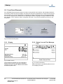
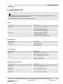
5 Startup.................................................................................................................................................. 55
5.1 Introduction................................................................................................................................... 55
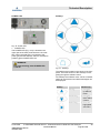
5.2 Front Panel Elements.................................................................................................................... 56
5.2.1 Display....................................................................................................................................... 56
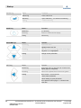
5.2.2 Status Line and Text Message Line........................................................................................... 56
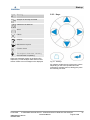
5.2.3 Keys........................................................................................................................................... 57
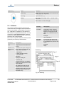
5.3 Software........................................................................................................................................ 59
5.3.1 Access Levels and Codes.......................................................................................................... 60
Table of contents
23.09.2020X-STREAM Enhanced XECLD - Chemiluminescence Detection Gas Analyzer4
00809-0100-3975, Rev AA
November 2020
Instruction Manual
Page 4 of 264

5.3.2 Special Messages...................................................................................................................... 61
5.4 Powering Up.................................................................................................................................. 62
5.4.1 Boot Sequence........................................................................................................................... 63
5.4.2 Measurement Display................................................................................................................ 63
5.5 Selecting the Language................................................................................................................ 63
5.6 Checking the Settings................................................................................................................... 64
5.6.1 Installed Options........................................................................................................................ 65
5.6.2 Configuring the Display.............................................................................................................. 65
5.6.3 Calibration/Validation Setup....................................................................................................... 66
5.6.4 Setting the Analog Outputs........................................................................................................ 68
5.6.5 Setting Concentration Alarms.................................................................................................... 72
5.6.6 Backup the Settings................................................................................................................... 73
5.7 Performing a Calibration............................................................................................................... 74
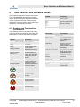
6 User Interface and Software Menus.................................................................................................. 75
6.1 Symbols and Typographical Conventions..................................................................................... 75
6.2 Menu System................................................................................................................................ 76
6.2.1 Switching On.............................................................................................................................. 79
6.2.2 Control Menu.............................................................................................................................. 80
6.2.3 Setup Menu................................................................................................................................ 92
6.2.4 Status Menu............................................................................................................................. 149
6.2.5 Info Menu................................................................................................................................. 158
6.2.6 Service Menu........................................................................................................................... 159
7 Installation......................................................................................................................................... 161
7.1 Safety on Installation................................................................................................................... 161
7.2 Assembly, Location and Mounting Requirements....................................................................... 161
7.3 Transport..................................................................................................................................... 162
7.4 Unpacking................................................................................................................................... 162
7.4.1 Scope of Delivery..................................................................................................................... 162
7.4.2 Disposing of Packaging............................................................................................................ 163
7.5 Mechanical installation................................................................................................................ 163
7.5.1 Connecting Rack Mount Brackets............................................................................................ 163
7.5.2 Connecting Housing Feet......................................................................................................... 164
7.6 Gas Conditioning......................................................................................................................... 165
7.7 Connecting gas lines................................................................................................................... 166
7.8 Establishing Electrical Connection.............................................................................................. 166
7.9 Notes on Wiring........................................................................................................................... 167
7.9.1 Connecting Shields.................................................................................................................. 167
7.9.2 Wiring different types of loads.................................................................................................. 169
8 Continuous operation....................................................................................................................... 171
8.1 How to measure NO.................................................................................................................... 171
8.2 How to measure NO
x
.................................................................................................................. 171
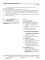
9 Maintenance and Other Procedures................................................................................................ 174
9.1 Safety on Maintenance............................................................................................................... 174
9.2 Maintenance Overview................................................................................................................ 174
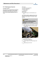
9.3 Preparing Maintenance............................................................................................................... 175
Table of contents
23.09.2020 X-STREAM Enhanced XECLD - Chemiluminescence Detection Gas Analyzer 5
00809-0100-3975, Rev AA
November 2020
Instruction Manual
Page 5 of 264

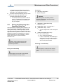
9.3.1 Purging Gas Lines.................................................................................................................... 175
9.3.2 Making Measuring Unit Accessible.......................................................................................... 176
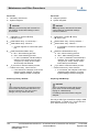
9.4 Cleaning the analyzer................................................................................................................. 177
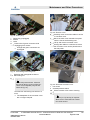
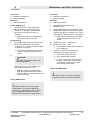
9.5 Exchanging Converter................................................................................................................. 178
9.6 Exchanging Power Connector Fuse............................................................................................ 184
9.7 Exchanging Power Supply Fuses............................................................................................... 185
9.8 Exchanging Housing Filter.......................................................................................................... 186
9.9 Performing a Leakage Test......................................................................................................... 187
9.10 Fine Adjusting Pressure Measurements................................................................................... 188
9.11 Saving and Restoring Configuration Data Sets......................................................................... 189
9.12 Handling Log Files.................................................................................................................... 192
9.12.1 Configuring Log Files............................................................................................................. 193
9.12.2 Exporting log files................................................................................................................... 193
9.13 Accessing via Web Browser...................................................................................................... 194
9.13.1 Connecting via Network......................................................................................................... 194
9.13.2 Connecting via Crossover Cable............................................................................................ 194
10 Calibration and Validation Procedures........................................................................................... 196
10.1 Safety on Calibration and Validation......................................................................................... 196
10.2 Information on Calibration and Validation................................................................................. 196
10.3 Preparing Calibration or Validation............................................................................................ 197
10.4 Performing Manual Calibration and Validation.......................................................................... 199
10.4.1 Performing Manual Calibration............................................................................................... 199
10.4.2 Performing Manual Validation................................................................................................ 201
10.5 Performing Non-Manual Calibration.......................................................................................... 202
10.5.1 Supplying Calibration and Validation Gases.......................................................................... 202
10.5.2 Assigning Digital Outputs to External Valves......................................................................... 203
10.5.3 Valve Assignment for Valve Supported Calibrations and Validations..................................... 205
10.5.4 Performing Advanced Calibration.......................................................................................... 205
10.5.5 Performing Remote Calibration/Validation............................................................................. 207
10.5.6 Performing Unattended Calibration/Validation....................................................................... 208
10.6 Performing NO- and NO
X
Calibration........................................................................................ 210
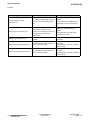
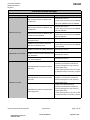
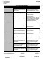
11 Troubleshooting................................................................................................................................ 212
11.1 Troubleshooting Safety.............................................................................................................. 212
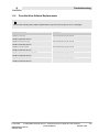
11.2 Possible Wear-Related Replacements...................................................................................... 213
12 Service Information........................................................................................................................... 214
12.1 Customer Service...................................................................................................................... 214
13 Glossary............................................................................................................................................. 215
14 Index................................................................................................................................................... 216
Appendix............................................................................................................................................ 217
A Potentially Poisonous Substances ................................................................................................ 218
B PLC Quick Reference Card ............................................................................................................. 219
C
Spare Parts List .................................................................................................................................
D
Safety Data Sheets ............................................................................................................................
E
Troubleshooting .................................................................................................................................
Table of contents
23.09.2020X-STREAM Enhanced XECLD - Chemiluminescence Detection Gas Analyzer6
00809-0100-3975, Rev AA
November 2020
Instruction Manual
Page 6 of 264

E.1
XE-related Troubleshooting ........................................................................................................
E.2
CLD-related Troubleshooting ......................................................................................................
Table of contents
23.09.2020 X-STREAM Enhanced XECLD - Chemiluminescence Detection Gas Analyzer 7
00809-0100-3975, Rev AA
November 2020
Instruction Manual
Page 7 of 264

1 Safety Instructions
1.1 Symbols Used On and Inside the Unit
1.1.1 Housing Signage
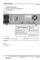
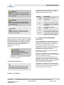
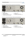
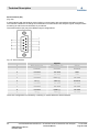
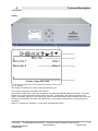
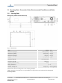
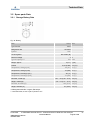
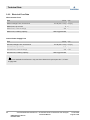
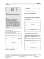
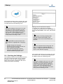
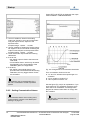
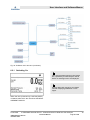
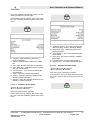
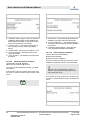
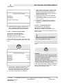
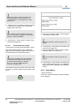
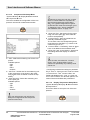
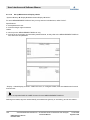
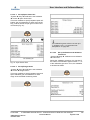
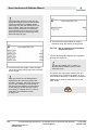
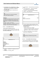
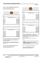
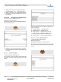
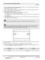
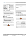
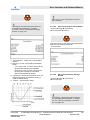
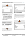
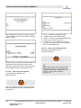
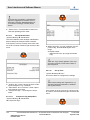
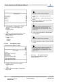
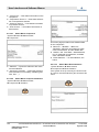
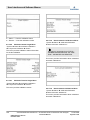
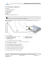
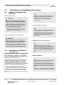
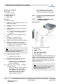
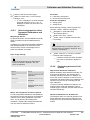
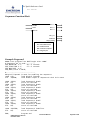
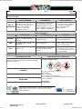
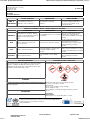
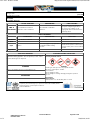
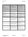
Nameplate
All configurations
Fig. 1: Nameplate
1 Product type
2 Channel 1: Measurement range (ppm)
3 Channel 1: Maximum measurement range (ppm)
4 Serial number
The nameplate (Fig. 1) is located on the rear panel. It contains information about the exact configuration of
the analyzer.
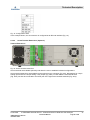
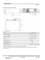
Back panel
All configurations
Safety Instructions
23.09.2020X-STREAM Enhanced XECLD - Chemiluminescence Detection Gas Analyzer8
00809-0100-3975, Rev AA
November 2020
Instruction Manual
Page 8 of 264

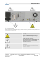
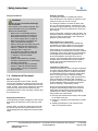
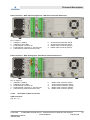
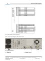
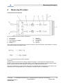
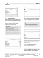
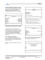
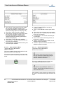
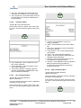
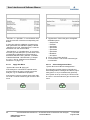
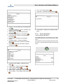
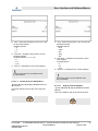
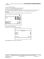
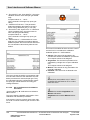
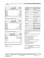
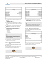
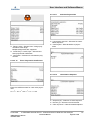
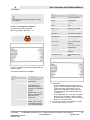
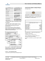
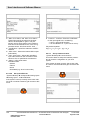
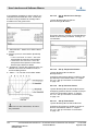
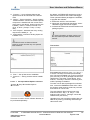
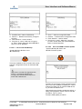
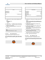
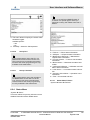
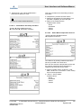
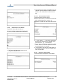
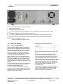
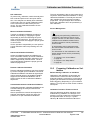
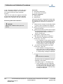
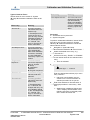
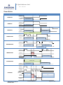
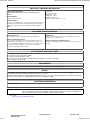
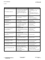
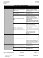
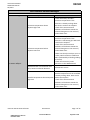
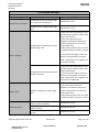
Fig. 2: Signage (backpanel)
On the back panel the signage shown in (Fig. 2) indicates dangerously hot surfaces, rotating fans and a sep-
arate connector for protective earth.
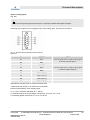
Sign Meaning
Hot Surfaces!
First turn off the device and let it cool down for
approx. 30 min before touching the marked parts.
A
Possible contact with Electrictity!
Never touch live parts (e. g. damaged cables) and
only remove any covers on the backpanel as
described in this manual.
B
Rotating Fan!
Never insert body parts or other objects into the
marked fan-openings.
Safety Instructions
23.09.2020 X-STREAM Enhanced XECLD - Chemiluminescence Detection Gas Analyzer 9
00809-0100-3975, Rev AA
November 2020
Instruction Manual
Page 9 of 264

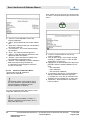
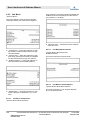
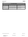
Sign Meaning
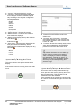
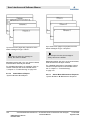
Equipotential bonding connector.
On-site equipotential bonding should be connected
at the marked position.
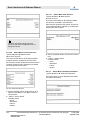
Top Cover
All configurations
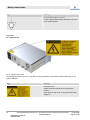
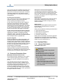
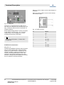
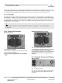
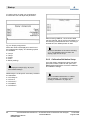
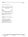
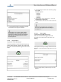
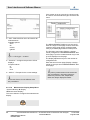
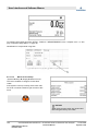
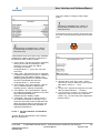
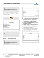
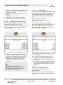
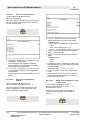
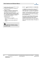
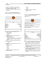
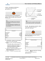
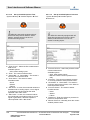
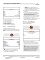
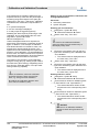
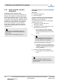
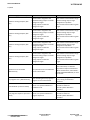
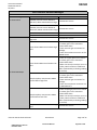
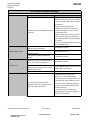
Fig. 3: Signage (top cover)
On the backside of the top cover a sign with a warning regarding a potential electrical hazard (Fig. 3, top
right) is attached.
Sign Meaning
Electrical Shock!
Always disconnect power before opening the
housing.
Never open the top cover or any panel with power
plugged in.
Safety Instructions
23.09.2020X-STREAM Enhanced XECLD - Chemiluminescence Detection Gas Analyzer10
00809-0100-3975, Rev AA
November 2020
Instruction Manual
Page 10 of 264

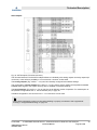
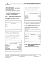
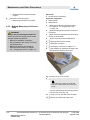
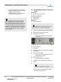
1.1.2 Signage Below Covers
Module Cover
All configurations
The module cover is only visible after removing the top cover.
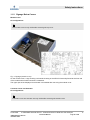
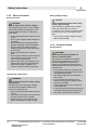
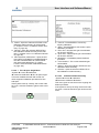
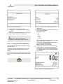
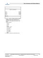
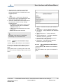
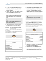
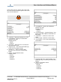
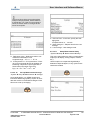
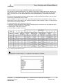
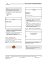
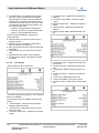
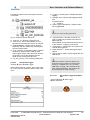
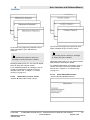
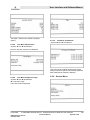
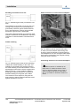
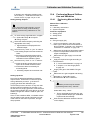
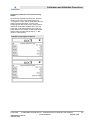
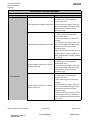
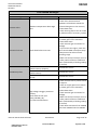
Fig. 4: Signage (module cover)
On the module cover, a sign showing a schematic drawing of the XECLD Personality Board at the front end
of the module with marked connectors is attached.
The upper part of the displayed circuit board is accessible after removing the module cover.
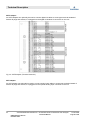
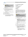
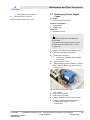
Converter Cover and Ozonator
All configurations
Converter cover and ozonator are only visible after removing the module cover.
Safety Instructions
23.09.2020 X-STREAM Enhanced XECLD - Chemiluminescence Detection Gas Analyzer 11
00809-0100-3975, Rev AA
November 2020
Instruction Manual
Page 11 of 264

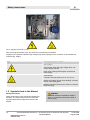
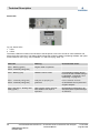
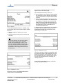
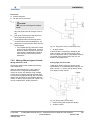
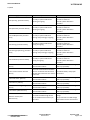
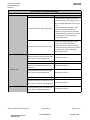
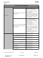
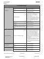
Fig. 5: Signage (converter cover)
After removing the module cover, the converter cover becomes accessible.
Signage on the ozonator indicates high voltage (Fig. 5/left). Signage on the converter cover indicates hot
surfaces (Fig. 5/right).
Sign Meaning in product context
High Voltage!
The ozonator works with high voltage which can
result in electric shocks.
Never open housing with analyzer connected to
power supply.
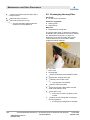
Hot Surfaces!
Converter case may heat up to 75 °C (170 °F).
Always wear safety gloves when handling converter
case or surrounding parts.
Measure temperature and let the surface cool down
before touching.
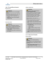
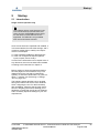
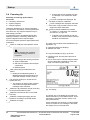
1.2 Symbols Used in this Manual
Safety Instructions
Safety instructions in this manual are identified by
symbols. The safety instructions are introduced
by signal words which express the extent of the
hazard.
DANGER!
DANGER indicates a hazardous situation
which, if not avoided, will result in death or
serious injury.
Safety Instructions
23.09.2020X-STREAM Enhanced XECLD - Chemiluminescence Detection Gas Analyzer12
00809-0100-3975, Rev AA
November 2020
Instruction Manual
Page 12 of 264

WARNING!
WARNING indicates a hazardous situation
which, if not avoided, could result in death
or serious injury.
CAUTION!
CAUTION indicates a hazardous situation
which, if not avoided, could result in minor
or moderate injury.
NOTICE!
NOTICE indicates important, non-safety-
related information, such as property and
environmental damage.
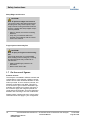
Safety Instructions in Procedural Instructions
Safety instructions can refer to specific, individual
procedural instructions. Such safety instructions
are embedded in the procedural instructions so
that they do not interrupt the reading flow when
performing the activity. The signal words
described above are used.
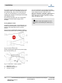
Example:
WARNING!
Check temperature before
touching heater jacket. If too hot
let it cool down!
Carefully pull out heater jacket in the direc-
tion of the rear panel.
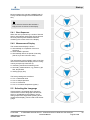
Tips and Recommendations
This symbol highlights useful tips and rec-
ommendations, as well as useful informa-
tion for efficient and fault-free operation.
Identifiers in this Manual
To highlight procedural instructions, results, lists,
references, and other elements, the following
identifiers are used in this manual:
Identifier Explanation
Step-by-step procedural
instructions
ð
Results of procedural steps
References to sections of this
manual and to other applicable
documents
Lists without a defined
sequence
[Button] Controls or signals (e.g., dis-
play elements or signal lamps)
“Display” Screen elements (e.g., buttons,
assignment of function keys)
1.3 Intended Use Statement
Intended Use
The X-STREAM Enhanced Chemiluminescence
Detector (XECLD) is an analyzer intended for
measurement of NO/NO
2
/NO
x
concentrations in
exhaust fumes and clean gas mixtures.
The analyzed exhaust fumes may come from all
possible types of power plants with burning pro-
cesses or from combustion engines.
Furthermore, the XECLD can be used for gas
purity measurements.
In principle, the XECLD is fit for analyzing non-
flammable gases and can be set up as a tabletop
unit or as a rackmount device.
The XECLD may only be supplied with power
and gases and be operated in surroundings as
specified in this manual (
Ä
Chapter 3.1 “Housing
Data, Connection Data, Environmental Condi-
tions and Emissions” on page 43).
The Analyzer is intended for commercial use in
industrial or non-industrial sectors. The intended
use is limited to measuring and testing where
usage in laboratories is included.
Safety Instructions
23.09.2020 X-STREAM Enhanced XECLD - Chemiluminescence Detection Gas Analyzer 13
00809-0100-3975, Rev AA
November 2020
Instruction Manual
Page 13 of 264

Dangerous Misuse
WARNING!
Danger of injury and material damage
due to misuse!
If the device is not used as intended, dan-
gerous situations may occur. Material
assets may be damaged.
– Never use in unventilated locations.
– Only supply Analyzer with gases as
described in this manual
Ä
Chapter
3.1.4 “Gas Supply Data” on page 46.
– Make sure that gas connections are
never unintentionally swapped.
– Always check gas connections and tub-
ings for leakage as described in this
manual
Ä
Chapter 9.9 “Performing a
Leakage Test” on page 187.
– Only operate the Analyzer within the
boundaries specified in this manual
Ä
Chapter 3 “Technical Data”
on page 42.
– Always check additional operating
boundary restrictions due to individually
ordered configurations.
– The Analyzer may only be operated
indoors in water and dust-protected
environments. Use only in explosion-
protected areas.
1.4 Authorized Personnel
Special Training
Authorized personnel who install, operate,
service and maintain the analyzer need to be fully
instructed and trained. Authorized personnel who
install, operate, service and maintain the analyzer
need to be fully instructed and trained by the
qualified personnel of the operating company and
the manufacturer.
Required Qualifications
TThe following job titles will appear in this manual
allocated to procedures for which they are quali-
fied:
Always make sure that only personnel that meet
the special requirements as described in the fol-
lowing paragraphs are assigned to the described
tasks.
Analyzer operator
The Analyzer operator is qualified to perform
basic tasks that do not require the opening of the
Analyzer housing or the use of tools.
The Analyzer operator is trained in safety mat-
ters, on-site special features, regulations on-site
and basics of gas measuring in a way that meets
legal and other official requirements to work with
the Analyzer.
Due to personality, experience and education, the
Analyzer operator is capable of working in such a
way as to keep all personnel in the industrial or
laboratory environment safe.
Authorized service personnel
Authorized service personnel are trained and
authorized by Emerson Rosemount to perform
specific service related tasks on the Analyzer.
Authorized service personnel have been exten-
sively trained to understand the Emerson exhaust
measuring product lines and have acquired deep
knowledge about local safety regulations and
technical standards during previous roles or
training. The knowledge and experience gained
enables these authorized service personnel to
identify and avoid potential danger for them-
selves and others.
Laboratory researchers
Laboratory researchers have a locally recognized
university diploma (Bachelor’s degree equivalent
or higher) qualifying them to analyze automotive
and industrial exhausts. Laboratory researchers
have, in the scope of their activities, already
gained experience in working with technical labo-
ratory equipment (measuring and monitoring
devices). Laboratory researchers are familiar with
locally applicable safety regulations and guide-
lines for working in a laboratory setting.
Due to their professional experience and their
analytical, methodological and technical knowl-
edge gained through their studies, laboratory
researchers are able to safely perform the fol-
lowing tasks with valid results:
n Erecting safe measurement setups with regard
to the state-of-the-art.
n Designing, evaluating and interpreting a series
of tests.
n Adapting parameters of the measurement
setup in a targeted manner.
Safety Instructions
23.09.2020X-STREAM Enhanced XECLD - Chemiluminescence Detection Gas Analyzer14
00809-0100-3975, Rev AA
November 2020
Instruction Manual
Page 14 of 264

The Analyzer-specific knowledge and skills of the
laboratory researcher exceed or at least match
those of an on-site service technician. Therefore
Laboratory researchers may perform all Ana-
lyzer-related tasks, an on-site service technician
is required for.
On-site service technician
The on-site service technician is assigned by the
operator to perform service tasks that may
involve opening the Analyzer housing.
On-site service technicians are also capable of
performing comprehensive repair work which
demands manual dexterity and a high level of
mechanical or technical qualification. This qualifi-
cation enables the on-site service technician to
for example handle fasteners, sheet metal parts,
electrical components and fragile components.
On-site service technicians are trained, have the
expertise, and have familiarity with all applicable
regulations to be able to complete the tasks
entrusted to them. They are also able to inde-
pendently, detect and avoid any possible hazards
at the Analyzer itself or operation site.
System integrator
Systems integrators are trained specialists, who
are familiar with the interfaces provided by the
Analyzer and its specification. System integrators
are allowed to perform each and every action on
the device in this manual and are able to connect
the device to appropriate external systems for
processing the counting data.
System integrators are familiar with the locally
applicable safety regulations and guidelines for
working in an industrial environment (for example
a power plant or incineration facility) setting.
1.5 Personal Protective Gear
Mandatory Protective Gear on Site
Only Analyzer-specific stipulations can be given
in this manual regarding the protective equip-
ment, since specific regulations on site are not
known.
The required special protective equipment for
working on site must be worn in addition to the
protective equipment described in this manual. If
the protective equipment described in this
manual (for example safety gloves) is the same
as in the operating instructions of other manufac-
turers, always wear the version which guarantees
the higher standard of safety.
Description of Protective Equipment
The following list describes all protective equip-
ment that must be worn for working with the Ana-
lyzer. At the introduction of every step-by-step
instruction, the specific protective equipment that
is to be worn is listed.
Safety gloves
Safety gloves are designed to protect the hands
from friction, abrasions, puncture wounds or
deeper wounds as well as coming into contact
with hot surfaces.
Safety shoes
Safety shoes protect against injuries of the feet
due to falling or pointed objects, as well as
against slipping.
Safety shoes exhibit the following characteristics:
n High skid resistance
n Steel caps as toe protection
n Strong upper material
n Puncture-resistant soles
Safety shoes must satisfy at least the applicable
requirements of protection class 3 according to
ISO 20345 or the requirements of other local reg-
ulations such as ASTM F2413-1
1.
1.6 Residual Risks
1.6.1 Unspecified Hazard
Unsuitable spare parts
WARNING!
Danger of injuries when using unsuit-
able spare parts!
If unsuitable spare parts are used, unfor-
seeable risks may arise. Fire, electrical
shocks, gas poisonings, cuts or other inju-
ries may be the result if unsuitable spare
parts are used.
– Only purchase original spare parts from
the manufacturer.
– Order only and exactly the spare parts
listed on the spare parts list in this
manual or a spare parts list provided by
the manufacturer.
Safety Instructions
23.09.2020 X-STREAM Enhanced XECLD - Chemiluminescence Detection Gas Analyzer 15
00809-0100-3975, Rev AA
November 2020
Instruction Manual
Page 15 of 264

1.6.2 Electrical Hazard
Electrical Shock
DANGER!
Risk of death due to electric voltage!
The Analyzer works from a mains voltage.
Incorrectly handling the Analyzer or con-
necting cables can result in a fatal elec-
trical shock.
– Do not operate Analyzer without secure
covers.
– Do not open Analyzer whilst Analyzer is
energized.
– Do not operate with damaged cables.
Replace damaged cables immediately.
– Do not perform any tasks on mains-
voltage-components. Use licensed elec-
tricians only!
– Never operate without a protective
earth.
– Do not replace cables or other electrical
components of the Analyzer on your
own. Contact manufacturer.
– Never connect the power supply to any
voltage other than that specified within
the technical data
Ä
Chapter 3.1.3
“Power Connection Data” on page 45.
High Voltage Components
WARNING!
Risk of electrical shock on high voltage
components!
The Ozonator works with high voltages.
Touching the energized ozonator may
result in an electric shock.
– Do not operate Ozonator without secure
covers.
– Only allow authorized service personnel
to perform tasks on the ozonator.
– Never open any cover while the Ana-
lyzer is connected to a power supply.
Wrong Supply Voltage
NOTICE!
Risk of damaged Analyzer when using
wrong supply voltage!
If the Analyzer is supplied with a voltage
other than specified in this manual
(
Ä
Chapter 3.1.3 “Power Connection Data”
on page 45) it may be damaged irrepar-
ably.
– Only connect supply voltages as speci-
fied in technical data.
1.6.3 Chemical Hazard
Harmful Gases
WARNING!
Risk of poisoning by inhalation of
ozone or exhaust fumes!
The Analyzer is supplied with exhaust
fumes and generates Ozone. Ozone is
harmful to health and should not be
inhaled in concentrations above the offi-
cially specified limits. Exhaust fumes may
be poisonous.
– Only use the Analyzer in locations that
have adequate ventilation that meet the
local legal requirements.
– Test the gas tightness as described in
this manual.
– Do not operate the Analyzer with a
defective housing fans. Replace defec-
tive fan immediately.
– Treat exhaust gases only according to
local regulations.
– Purge analyzer with nitrogen (N
2
) before
opening housing and gas connections.
– Only open unpressurized Analyzers.
Safety Instructions
23.09.2020X-STREAM Enhanced XECLD - Chemiluminescence Detection Gas Analyzer16
00809-0100-3975, Rev AA
November 2020
Instruction Manual
Page 16 of 264

1.6.4 Fire and Burns Hazards
Electrical Fire
WARNING!
Fire hazard due to use of unsuitable
fuses!
If unsuitable fuses are used or fuses are
bridged, electrical fires may occur.
– Only use fuses as described in this
manual.
– Never bridge fuses. Never operate
without fuses.
Flammable Gases
WARNING!
Risk of fire and explosion injuries!
If the Analyzer is supplied with flammable
gases fire and explosions may occur.
– Never supply the Analyzer with flam-
mable gases.
– Always purge gas paths as described in
this manual.
Heated Components
WARNING!
Risk of burns due to temperatures
exceeding specification!
Certain components can reach very high
temperatures on their surfaces. Contact
with these surfaces may cause burns:
Converter (Inner parts): 500 °C (930 °F)
Converter (Housing): 80 °C (176 °F)
Gas-Connectors: 75 °C (170 °F)
Module cover (top side): 90 °C (195 °F)
– Never operate with housing open.
– Never operate with a defective housing
fan.
– Always switch off first and allow to cool
for 60 minutes. Only when the Analyzer
has cooled down:
– Touch top cover.
– Open housing.
– Carry out work on the gas connec-
tions
– Follow the instructions in this manual
exactly for activities inside the housing.
– Observe signage indications of hot sur-
faces.
1.6.5 Mechanical Hazards
Falling Objects
WARNING!
Risk of injuries caused by falling
objects!
If the Analyzer or any components fall (for
example caused by mishandling), injuries
may result.
– Always wear additional protective gear
as described in this manual.
– Handle Analyzer and components with
care.
Safety Instructions
23.09.2020 X-STREAM Enhanced XECLD - Chemiluminescence Detection Gas Analyzer 17
00809-0100-3975, Rev AA
November 2020
Instruction Manual
Page 17 of 264

Sharp Edges and Corners
CAUTION!
Risk of injuries at edges and corners!
The rack mounting brackets protrude and
bumping them may cause injuries; espe-
cially in transit. During activities inside the
housing, contact with sharp-edged compo-
nents is possible.
– When in transit, remove the mounting
brackets.
– Only carry out activities within the
housing in accordance with the instruc-
tions in this manual.
Finger Injuries Caused by Fan
CAUTION!
Risk of injury to fingers on the housing
fan!
If the finger protection is not reinstalled
after working on the housing fan, crushing
and impact injuries may result if fan is
reached into.
– Always install finger protection as
described.
– Never reach into the fan.
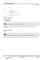
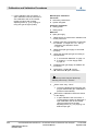
1.7 On the use of figures
Product variants
The Analyzer is available in different variants and
configurations. In this manual, a distinct configu-
ration is shown which illustrates all tasks or infor-
mation provided. In some sections however, the
Analyzer configuration may differ. This will be
more common in gas connector illustrations (for
example, the existence of a purge connector or
the connector type), the usage of optional I/O-
cards and screw terminals, and in the distinction
between rack mounting or the use of stand feet.
Please contact customer service if unsure some
information does not apply to your configuration.
Safety Instructions
23.09.2020X-STREAM Enhanced XECLD - Chemiluminescence Detection Gas Analyzer18
00809-0100-3975, Rev AA
November 2020
Instruction Manual
Page 18 of 264

2 Technical Description
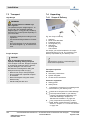
2.1 Tools and Consumable Mate-
rials
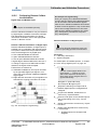
Tools
To work with the Analyzer, use a set of standard
tools (for example, screwdrivers (cross-head and
flat-head) and wrenches.
Additionally the following special tools are
needed:
External hexagon nut with extension (5.5 mm)
The external hexagon nut with extension enables
to unscrew hexagon socket nuts in an distance of
approx. 20 cm (8 in).
The width across flat-head screwdrivers must be
approx. 5.5 mm (0.22 in).
Consumable Materials
The following consumable materials are needed.
Do not use other materials than these described:
Materials:
n
Converter test gas supply
n
Detergents
n
Leakage test gas supply (N
2
or He)
n
Replacement fuse
n
Replacement housing filter
n
Span gas supply
n
USB storage device
n
Zero gas supply (N
2
)
n
Air-supply gas
Air-supply gas
Air-supply gas is pressurized or synthetic air and
meets the technical requirements
Ä
Chapter
3.1.4 “Gas Supply Data” on page 46.
Do not use pure oxygen as air-supply gas.
Converter test gas supply
Converter test gas has a known concentration of
NO
2
(< 500 ppm) and meets the technical
requirements.
A supply of converter test gas can be connected
to the sample-in-line independently from sample
gas or air supply.
Detergents
The detergent is not chemically aggressive, is
free of solvents and does not contain any hydro-
carbons.
Leakage test gas supply (N
2
or He)
A supply of test gas (N
2
or He) which can be con-
nected to the exhaust line independently from
sample gas or air supply (e. g. gas bottle).
The leakage test gas supply must be able to at
least build up pressure of 1,034 hPa (15 psig)
and must provide an option to shut down so that
connected gas lines remain under pressure.
Replacement fuse
The replacement fuse matches the description
and the technical data stated in the spare parts
list in this manual
Ä
“Fuses” on page 227.
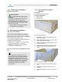
Replacement housing filter
The replacement housing filter is available at
Emerson Rosemount.
The filter fits into the seat at the air inlet at the
rear of the housing and meets the requirements
e. g. considering filtered particulate size.
Use replacement filters as listed on the spare
parts list only.
Span gas supply
Span gas has a known concentration of NO and
meets the technical requirements
Ä
Chapter
3.1.4 “Gas Supply Data” on page 46.
A supply of span gas can be connected to the
sample-in-line independently from sample gas.
Span gas should have a concentration of 80 % to
110 % of the upper measuring range limit to the
gas path. Using lower concentrations may
decrease accuracy when measuring above the
span gas concentration!
USB storage device
The USB-Storage Device is used for external
data backups and must meet the specifications of
USB 1.0 or higher. The device plug must be a
USB male connector (type A).
It is recommended to use storage devices manu-
factured by renowned brands such as SANDISK,
KINGSTON, TOSHIBA etc..
Always test functionality of USB-Storage Device
before using it for (important) backups.
Technical Description
23.09.2020 X-STREAM Enhanced XECLD - Chemiluminescence Detection Gas Analyzer 19
00809-0100-3975, Rev AA
November 2020
Instruction Manual
Page 19 of 264

Zero gas supply (N
2
)
The zero gas supply is N
2
of high purity.
The nitrogen should, as a minimum, be of quality
of 5.0, which means nitrogen of purity ≥
99.999 %. If such gas is not available, the substi-
tute must be dry, clean and free of corrosives or
components containing solvents. It has to be free
of components to be measured, to minimize
cross interferences.
The supply of zero gas (N
2
) can be connected to
the sample gas connector independently from
sample gas or air supply.
The zero gas supply must also meet the technical
requirements
Ä
Chapter 3.1.4 “Gas Supply Data”
on page 46.
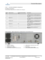
2.2 Inputs and Outputs
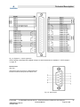
2.2.1 Inputs and Outputs: General
Information
Limits and SELV
All external inputs shall provide reinforced or
double insulation for protection against electric
shock and with output voltages below the limits of
6.3.1 of 61010-1 or 30 V RMS and 42.4 V peak
or 60 V DC.
Connect only secondary circuits that are
designed in a way that under normal and single
fault conditions, the voltage between any two
parts of the SELV circuit does not exceed safe
values.
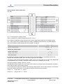
2.2.2 Inputs and Outputs: Data Con-
nectors
Technical Description
23.09.2020X-STREAM Enhanced XECLD - Chemiluminescence Detection Gas Analyzer20
00809-0100-3975, Rev AA
November 2020
Instruction Manual
Page 20 of 264
La pagina si sta caricando...
La pagina si sta caricando...
La pagina si sta caricando...
La pagina si sta caricando...
La pagina si sta caricando...
La pagina si sta caricando...
La pagina si sta caricando...
La pagina si sta caricando...
La pagina si sta caricando...
La pagina si sta caricando...
La pagina si sta caricando...
La pagina si sta caricando...
La pagina si sta caricando...
La pagina si sta caricando...
La pagina si sta caricando...
La pagina si sta caricando...
La pagina si sta caricando...
La pagina si sta caricando...
La pagina si sta caricando...
La pagina si sta caricando...
La pagina si sta caricando...
La pagina si sta caricando...
La pagina si sta caricando...
La pagina si sta caricando...
La pagina si sta caricando...
La pagina si sta caricando...
La pagina si sta caricando...
La pagina si sta caricando...
La pagina si sta caricando...
La pagina si sta caricando...
La pagina si sta caricando...
La pagina si sta caricando...
La pagina si sta caricando...
La pagina si sta caricando...
La pagina si sta caricando...
La pagina si sta caricando...
La pagina si sta caricando...
La pagina si sta caricando...
La pagina si sta caricando...
La pagina si sta caricando...
La pagina si sta caricando...
La pagina si sta caricando...
La pagina si sta caricando...
La pagina si sta caricando...
La pagina si sta caricando...
La pagina si sta caricando...
La pagina si sta caricando...
La pagina si sta caricando...
La pagina si sta caricando...
La pagina si sta caricando...
La pagina si sta caricando...
La pagina si sta caricando...
La pagina si sta caricando...
La pagina si sta caricando...
La pagina si sta caricando...
La pagina si sta caricando...
La pagina si sta caricando...
La pagina si sta caricando...
La pagina si sta caricando...
La pagina si sta caricando...
La pagina si sta caricando...
La pagina si sta caricando...
La pagina si sta caricando...
La pagina si sta caricando...
La pagina si sta caricando...
La pagina si sta caricando...
La pagina si sta caricando...
La pagina si sta caricando...
La pagina si sta caricando...
La pagina si sta caricando...
La pagina si sta caricando...
La pagina si sta caricando...
La pagina si sta caricando...
La pagina si sta caricando...
La pagina si sta caricando...
La pagina si sta caricando...
La pagina si sta caricando...
La pagina si sta caricando...
La pagina si sta caricando...
La pagina si sta caricando...
La pagina si sta caricando...
La pagina si sta caricando...
La pagina si sta caricando...
La pagina si sta caricando...
La pagina si sta caricando...
La pagina si sta caricando...
La pagina si sta caricando...
La pagina si sta caricando...
La pagina si sta caricando...
La pagina si sta caricando...
La pagina si sta caricando...
La pagina si sta caricando...
La pagina si sta caricando...
La pagina si sta caricando...
La pagina si sta caricando...
La pagina si sta caricando...
La pagina si sta caricando...
La pagina si sta caricando...
La pagina si sta caricando...
La pagina si sta caricando...
La pagina si sta caricando...
La pagina si sta caricando...
La pagina si sta caricando...
La pagina si sta caricando...
La pagina si sta caricando...
La pagina si sta caricando...
La pagina si sta caricando...
La pagina si sta caricando...
La pagina si sta caricando...
La pagina si sta caricando...
La pagina si sta caricando...
La pagina si sta caricando...
La pagina si sta caricando...
La pagina si sta caricando...
La pagina si sta caricando...
La pagina si sta caricando...
La pagina si sta caricando...
La pagina si sta caricando...
La pagina si sta caricando...
La pagina si sta caricando...
La pagina si sta caricando...
La pagina si sta caricando...
La pagina si sta caricando...
La pagina si sta caricando...
La pagina si sta caricando...
La pagina si sta caricando...
La pagina si sta caricando...
La pagina si sta caricando...
La pagina si sta caricando...
La pagina si sta caricando...
La pagina si sta caricando...
La pagina si sta caricando...
La pagina si sta caricando...
La pagina si sta caricando...
La pagina si sta caricando...
La pagina si sta caricando...
La pagina si sta caricando...
La pagina si sta caricando...
La pagina si sta caricando...
La pagina si sta caricando...
La pagina si sta caricando...
La pagina si sta caricando...
La pagina si sta caricando...
La pagina si sta caricando...
La pagina si sta caricando...
La pagina si sta caricando...
La pagina si sta caricando...
La pagina si sta caricando...
La pagina si sta caricando...
La pagina si sta caricando...
La pagina si sta caricando...
La pagina si sta caricando...
La pagina si sta caricando...
La pagina si sta caricando...
La pagina si sta caricando...
La pagina si sta caricando...
La pagina si sta caricando...
La pagina si sta caricando...
La pagina si sta caricando...
La pagina si sta caricando...
La pagina si sta caricando...
La pagina si sta caricando...
La pagina si sta caricando...
La pagina si sta caricando...
La pagina si sta caricando...
La pagina si sta caricando...
La pagina si sta caricando...
La pagina si sta caricando...
La pagina si sta caricando...
La pagina si sta caricando...
La pagina si sta caricando...
La pagina si sta caricando...
La pagina si sta caricando...
La pagina si sta caricando...
La pagina si sta caricando...
La pagina si sta caricando...
La pagina si sta caricando...
La pagina si sta caricando...
La pagina si sta caricando...
La pagina si sta caricando...
La pagina si sta caricando...
La pagina si sta caricando...
La pagina si sta caricando...
La pagina si sta caricando...
La pagina si sta caricando...
La pagina si sta caricando...
La pagina si sta caricando...
La pagina si sta caricando...
La pagina si sta caricando...
La pagina si sta caricando...
La pagina si sta caricando...
La pagina si sta caricando...
La pagina si sta caricando...
La pagina si sta caricando...
La pagina si sta caricando...
La pagina si sta caricando...
La pagina si sta caricando...
La pagina si sta caricando...
La pagina si sta caricando...
La pagina si sta caricando...
La pagina si sta caricando...
La pagina si sta caricando...
La pagina si sta caricando...
La pagina si sta caricando...
La pagina si sta caricando...
La pagina si sta caricando...
La pagina si sta caricando...
La pagina si sta caricando...
La pagina si sta caricando...
La pagina si sta caricando...
La pagina si sta caricando...
La pagina si sta caricando...
La pagina si sta caricando...
La pagina si sta caricando...
La pagina si sta caricando...
La pagina si sta caricando...
La pagina si sta caricando...
La pagina si sta caricando...
La pagina si sta caricando...
La pagina si sta caricando...
La pagina si sta caricando...
La pagina si sta caricando...
La pagina si sta caricando...
La pagina si sta caricando...
La pagina si sta caricando...
La pagina si sta caricando...
La pagina si sta caricando...
La pagina si sta caricando...
La pagina si sta caricando...
La pagina si sta caricando...
La pagina si sta caricando...
La pagina si sta caricando...
La pagina si sta caricando...
La pagina si sta caricando...
La pagina si sta caricando...
La pagina si sta caricando...
La pagina si sta caricando...
La pagina si sta caricando...
La pagina si sta caricando...
La pagina si sta caricando...
La pagina si sta caricando...
La pagina si sta caricando...
La pagina si sta caricando...
La pagina si sta caricando...
-
 1
1
-
 2
2
-
 3
3
-
 4
4
-
 5
5
-
 6
6
-
 7
7
-
 8
8
-
 9
9
-
 10
10
-
 11
11
-
 12
12
-
 13
13
-
 14
14
-
 15
15
-
 16
16
-
 17
17
-
 18
18
-
 19
19
-
 20
20
-
 21
21
-
 22
22
-
 23
23
-
 24
24
-
 25
25
-
 26
26
-
 27
27
-
 28
28
-
 29
29
-
 30
30
-
 31
31
-
 32
32
-
 33
33
-
 34
34
-
 35
35
-
 36
36
-
 37
37
-
 38
38
-
 39
39
-
 40
40
-
 41
41
-
 42
42
-
 43
43
-
 44
44
-
 45
45
-
 46
46
-
 47
47
-
 48
48
-
 49
49
-
 50
50
-
 51
51
-
 52
52
-
 53
53
-
 54
54
-
 55
55
-
 56
56
-
 57
57
-
 58
58
-
 59
59
-
 60
60
-
 61
61
-
 62
62
-
 63
63
-
 64
64
-
 65
65
-
 66
66
-
 67
67
-
 68
68
-
 69
69
-
 70
70
-
 71
71
-
 72
72
-
 73
73
-
 74
74
-
 75
75
-
 76
76
-
 77
77
-
 78
78
-
 79
79
-
 80
80
-
 81
81
-
 82
82
-
 83
83
-
 84
84
-
 85
85
-
 86
86
-
 87
87
-
 88
88
-
 89
89
-
 90
90
-
 91
91
-
 92
92
-
 93
93
-
 94
94
-
 95
95
-
 96
96
-
 97
97
-
 98
98
-
 99
99
-
 100
100
-
 101
101
-
 102
102
-
 103
103
-
 104
104
-
 105
105
-
 106
106
-
 107
107
-
 108
108
-
 109
109
-
 110
110
-
 111
111
-
 112
112
-
 113
113
-
 114
114
-
 115
115
-
 116
116
-
 117
117
-
 118
118
-
 119
119
-
 120
120
-
 121
121
-
 122
122
-
 123
123
-
 124
124
-
 125
125
-
 126
126
-
 127
127
-
 128
128
-
 129
129
-
 130
130
-
 131
131
-
 132
132
-
 133
133
-
 134
134
-
 135
135
-
 136
136
-
 137
137
-
 138
138
-
 139
139
-
 140
140
-
 141
141
-
 142
142
-
 143
143
-
 144
144
-
 145
145
-
 146
146
-
 147
147
-
 148
148
-
 149
149
-
 150
150
-
 151
151
-
 152
152
-
 153
153
-
 154
154
-
 155
155
-
 156
156
-
 157
157
-
 158
158
-
 159
159
-
 160
160
-
 161
161
-
 162
162
-
 163
163
-
 164
164
-
 165
165
-
 166
166
-
 167
167
-
 168
168
-
 169
169
-
 170
170
-
 171
171
-
 172
172
-
 173
173
-
 174
174
-
 175
175
-
 176
176
-
 177
177
-
 178
178
-
 179
179
-
 180
180
-
 181
181
-
 182
182
-
 183
183
-
 184
184
-
 185
185
-
 186
186
-
 187
187
-
 188
188
-
 189
189
-
 190
190
-
 191
191
-
 192
192
-
 193
193
-
 194
194
-
 195
195
-
 196
196
-
 197
197
-
 198
198
-
 199
199
-
 200
200
-
 201
201
-
 202
202
-
 203
203
-
 204
204
-
 205
205
-
 206
206
-
 207
207
-
 208
208
-
 209
209
-
 210
210
-
 211
211
-
 212
212
-
 213
213
-
 214
214
-
 215
215
-
 216
216
-
 217
217
-
 218
218
-
 219
219
-
 220
220
-
 221
221
-
 222
222
-
 223
223
-
 224
224
-
 225
225
-
 226
226
-
 227
227
-
 228
228
-
 229
229
-
 230
230
-
 231
231
-
 232
232
-
 233
233
-
 234
234
-
 235
235
-
 236
236
-
 237
237
-
 238
238
-
 239
239
-
 240
240
-
 241
241
-
 242
242
-
 243
243
-
 244
244
-
 245
245
-
 246
246
-
 247
247
-
 248
248
-
 249
249
-
 250
250
-
 251
251
-
 252
252
-
 253
253
-
 254
254
-
 255
255
-
 256
256
-
 257
257
-
 258
258
-
 259
259
-
 260
260
-
 261
261
-
 262
262
-
 263
263
-
 264
264


Rosemount X-STREAM Enhanced XECLD Continuous Gas Analyzer Manuale del proprietario
- Tipo
- Manuale del proprietario
in altre lingue
Documenti correlati
-
Rosemount Misuratore di portata magnetico 8732EM con elettronica revisione 4 Manuale del proprietario
-
-
-
-
Altri documenti
-
 Hach Polymetron 9610sc SiO2 Guida d'installazione
-
 Hach Lange ORBISPHERE 3100 Basic User Manual
-
 Hach Lange ORBISPHERE 3100 Basic User Manual
-
 Hach pHD Sensor Manuale utente
-
 Hach NA5600 sc Na+ Operations
-
 Hach ORBISPHERE 510 Basic User Manual
-
 Hach ORBISPHERE 410 Basic User Manual
-
 Hach ORBISPHERE 410 Basic User Manual
-
Hach CL17sc Manuale utente
-
Sanyo MDF-C2156VANC Manuale utente


