Soundstream MTR-25-10W-RGBW Manuale utente
- Categoria
- Stroboscopi
- Tipo
- Manuale utente

MTR-25-10W-RGBW
25 X 10W RGBW 4IN1 LED Slim MATRIX BLINDER
Please read this manual carefully and proper take care of this manual
USER MANUAL

2
ENGLISH

3
ENGLISH
Dear customer,
First of all thanks far purchasing a SOUNDSATION® product. Our mission is to satisfy all possible
needs of musical instrument and professional audio and lighting users offering a wide range of
products using the latest technologies.
We hope you will be satised with this item and, if you want to collaborate, we are looking for a
feedback from you about the operation of the product and possible improvements to introduce in
the next future. Go to our website www.soundsationmusic.com and send an e-mail with your
opinion, this will help us to build instruments ever closer to customer’s real requirements.
One last thing: read this manual before using the instrument, an incorrect operation can cause
damages to you and to the unit. Take care!
The SOUNDSATION Team

4
ENGLISH
IMPORTANT SAFETY SYMBOLS
The symbol is used to indicate that some hazardous live terminals are
involved within this apparatus, even under the normal operating condi-
tions, which may be sufcient to constitute the risk of electric shock or
death.
The symbol is used in the service documentation to indicate that spe-
cic component shall be replaced only by the component specied in
that documentation for safety reasons.
Protective grounding terminal
Alternating current/voltage
Hazardous live terminal
Denotes the apparatus is turned on
Denotes the apparatus is turned off
WARNING:
Describes precautions that should be observed to prevent the danger
of injury or death to the operator.
CAUTION:
Describes precautions that should be observed to prevent danger of
the apparatus.
IMPORTANT SAFETY INSTRUCTIONS
f Read these instructions
f Keep these instructions
f Heed all warning
f Follow all instructions
Water / Moisture
This lighting is intended to indoor use only. To prevent risk of re or shock, do not
expose xture to rain or moisture. Make sure there are no ammable, explosive or
corrosive materials surrounded in 10 meters while operating.
Heat
The apparatus should be located away from heat sources such as radiators, stoves or
other appliances that produce heat. Fixture may carry high heat, do not aim at objective
exceeding 2 minutes.
Ventilation
The unit must be installed in a location with adequate ventilation, at least 5m away from

5
ENGLISH
adjacent surfaces. Be sure that no ventilation slots are blocked.
Object and Liquid Entry
Objects do not fall into and liquids are not spilled into the inside of the apparatus for
safety.
Power Cord and Plug
Protect the power cord from being walked on or pinched particularly at plugs, conve-
nience receptacles, and the point where they exit from the apparatus. Do not defeat the
safety purpose of the polarized or grounding-type plug. A polarized plug has two poles;
a grounding-type plug has two poles and a third grounding terminal. The third prong
is provided for your safety. If the provided plug does not t into your outlet, refer to an
electrician for replacement.
Power Supply
Always make sure that you are connecting to the proper voltage and the line voltage
not higher than stated on the decal or rear panel of the xture. Unplug this apparatus
during lightning storms or when unused for long periods of time.
Fuse
To prevent the risk of re and damaging the unit, please use only of the recommended
fuse type as described in the manual. Before replacing the fuse, make sure the unit
turned off and disconnected from the AC outlet.
Electrical Connection
Always disconnect from the power source before servicing or replacing fuse/lamp and
be sure to replace with same fuse/lamp size and type. Cut off power before moving, re-
pairing and cleaning the machine. Improper electrical wiring may invalidate the product
warranty.
To avoid electric shock, all xtures must be connected to circuits with a suitable ground.
Do not power on and power off the xture in a short time.
DMX connection
When use DMX controller, please make sure that there is no interference sources (e.g.
intercom, high frequency radio waves and radiation source.
Servicing
In case of failure or mis-function occurred, stop using the unit immediately. Never try to
repair the unit by yourself. Repairs carried out by unskilled people can lead to damage
or malfunction. Please contact the nearest authorized technical assistance center. Buy
the same spare parts/components from manufacturer directly.
Any damage that cased by violating this manual is out of insurance, our company will
not take the responsibility.

6
ENGLISH
MTR-25-10W-RGBW User manual
TABLE OF CONTENTS
1. PRODUCT SPECIFICATION ....................................................................................7
2. SETUP ......................................................................................................................8
2.1. Installation .............................................................................................................................8
2.2. Module Mechanical Connection ............................................................................................9
2.3. Connections ........................................................................................................................11
3. LED DISPLAY ........................................................................................................13
3.1. LED display function............................................................................................................13
3.2. Display function description.................................................................................................15
4. DEVICE USE AND SETTING .................................................................................17
4.1. 1pc use and display settings ...............................................................................................17
4.2. 4pcs use and display settings .............................................................................................17
4.3. 16pcs use and display settings ...........................................................................................18
4.4. LED Operation.....................................................................................................................19
4.5. DMX Controller or PC software ...........................................................................................19
5. CHANNEL MODES ................................................................................................22
5.1. 1CH Mode ...........................................................................................................................22
5.2. 4CH Mode ...........................................................................................................................22
5.3. 5CH Mode ...........................................................................................................................22
5.4. 25CH Mode .........................................................................................................................23
5.5. 75CH Mode .........................................................................................................................24
5.6. 100CH Mode .......................................................................................................................24
6. WARRANTY AND SERVICE ..................................................................................25
7. WARNING ..............................................................................................................26

7
ENGLISH
MTR-25-10W-RGBW User manual
1. PRODUCT SPECIFICATION
f Light source: 25 x 10W RGBW 4in1 High Brightness LED
f Pixel by pixel control, delivering versatile effects
f Coupling system cabinet to create structures with more units (max 4x4 = 16 units)
f Flight case to transport 4 units and store accessories (optional)
f Control modes: Sound Active, LED Auto Run, DMX Master/slave, ArtNet
f DMX Channel Modes: 1CH, 4CH, 5CH, 25CH, 75CH and 100CH
f Controllable by external controllers or computers (this requires third party equip-
ment)
f Smooth 0-100% dimmer
f Versatile Strobe Effects
f Flicker Free
f LED display interface, easy to control
f LED self test: R, G, B, W, RGBW
f Voltage: AC100-240V 50/60HZ
f Power Consumption: 300W
f Data In/Out: 3-Pin XLR and RJ45
f Fuse: F5A, 250V
f Size: 58 x 58 x 12cm
f Weight: 13kg

8
ENGLISH
MTR-25-10W-RGBW User manual
2. SETUP
2.1. Installation
Pay attention to safety! Please respectively consider the EN 60598-2-17 and
the national standard during the installation. The authorized dealer must
only carry out the installation.
The installation of the xture has to be built and constructed in a way that it can hold
10 times the weight for 1 hour without any harming demolition. The installation must
always be secured with a secondary safety attachment, e.g. an appropriate catch net.
This secondary safety attachment must be constructed in a way that no part of the
installation can fall down if the main attachment fails.
When rigging, de-rigging or servicing the xture staying in the area below the instal-
lation place, on bridges, under high working places and other endangered areas is
forbidden. The operator has to make sure that the safety measure and the machine’s
technical installation is approved by an expert before taking into operation for the rst
time and after changes before taking into operation anther time. He has also to make
sure that an expert approves safety measure and the machine’s technical installation
once a years.
WARNING:Thextureshouldbeinstalledoutsideareaswherepersonsmay
walkbyorbeseated.
IMPORTANT:Overheadriggingrequiresextensiveexperience,including
(butnotlimitedto)calculatingworkingloadlimits,installationmaterial
beingused,andperiodicsafetyinspectionofallinstallationmaterialand
theprojector.Ifyoulackthesequalications,donotattempttheinstallation
yourself,butinsteaduseaprofessionalstructuralrigger.Improperinstalla-
tioncanresultinbodilyinjuryorpropertyloss.
If the xture shall be lowered from the ceiling or high joists, professional trussing
systems have to be used. The xture must never be xed swinging freely in the room.
Before rigging make sure that the installation area can hold a minimum point load of 10
times the projector’s weight.
CAUTION:Fixturemaycausesevereinjurieswhencrashingdown.Ifyou
havedoubtsconcerningthesafetyofapossibleinstallation,donotinstall
thexture!
CAUTION:Usetwoappropriateclampstorigthextureonthetruss.Follow
theinstructionsmentionedatthebottomofthebase.Makesurethatthe
deviceisxedproperly!Ensurethatthestructure(truss)towhichyouare
attachingthexturesissecure.
DANGEROFFIRE!Wheninstallingthedevice,makesurethereisnohighly

9
ENGLISH
MTR-25-10W-RGBW User manual
inammablematerial(decorationarticles,etc.)withinadistanceofminimum
0.5 meter.
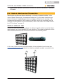
2.2. Module Mechanical Connection
Each module can be used either individually or in blocks of several modules. In the
case of Master/Slave mode, the maximum number is 16; in the case of external com-
puter software (not supplied), the maximum number is dened by the capacity of the
software and the number of DMX outputs of the DMX control unit connected from the
computer to the modules. For more information, refer to the section “4.5. DMX Control-
ler or PC software” on page 16.
Single module Use
As you can see from the following gure, the cabinet of each module is provided with a
swivel bracket and 2 small brackets for truss mounting. The screws on each side of the
swivel brackets allow the user to block the module in the desired position.
In the case of truss mounting with the brackets, it also advisable to use hooks (see
www.soundsationmusic.com website for details on available models) connected to the

10
ENGLISH
MTR-25-10W-RGBW User manual
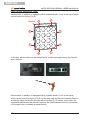
Multiple Module Use
Each module, in addition, is equipped with 4 rotatable hooks (1 to 4 in the gure) which
can be hooked to 4 pins (5 to 8).
8
7
1
2
3
4
6
5
Bracket
In this way, each module can be easily xed to another by simply turning the 4 hooks
with a hex key.
Each module, in addition, is equipped with 4 rotatable hooks (1 to 4 in the gure)
which can be hooked to 4 pins (5 to 8). In this way, each module can be easily xed to
another by simply turning the 4 hooks with a hex key (9). Of course, in this case, the
adjustable bracket must be removed and only the small brackets have to be mounted
on the upper row of modules as shown below.

11
ENGLISH
MTR-25-10W-RGBW User manual
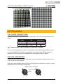
2.3. Connections
3.2.1 Mains Connections
Connect the device to the mains with the power-plug. The wire correspondence is as
follow:
Cable Pin International
Brown Live L
Blue Neutral N
Yellow/Green Earth
Theearthmusttobeconnected!Payattentiontosafety!
In case of a large number of units, it is advisable to use a three-phase mains connec-
tion and distribute the modules in equal parts on the three lines. Before taking into
operation for the rst time, the installation has to be approved by an expert.
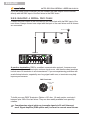
DMX-512 Connection
Wires must not come into contact with each other; otherwise the xtures will not work
at all, or will not work properly.
Only use a dual-shielded cable and 3-pin XLR plugs and connectors in order to control
with the xture or one xture with another.
DMX use of XLR connectors
1 = Ground / Shield
2 = DMX +
3 = DMX -
INPUT OUTPUT

12
ENGLISH
MTR-25-10W-RGBW User manual
If you are using a DMX controller, you can connect the DMX output of the controller
directly with the DMX input of the rst xture in the DMX chain.
3.2.3. Building a Serial DMX Chain
Connect the DMX output of the rst xture in the DMX chain with the DMX input of the
next xture. Always connect one output with the input of the next xture until all xtures
are connected.
DMX Termonator
Unit 1 Unit 2 Last Unit
DMX 512
A word on termination: DMX is a resilient communication protocol, however errors
still occasionally occur. Termination reduces signal errors, and therefore best practices
include use of a terminator in all circumstances. If you are experiencing problems with
erratic xture behavior, especially over long signal cable runs, a terminator may help
improve performance.
DMX Terminator
120ohm, 1/4W
resistor
To build your own DMX Terminator: Obtain a 120-ohm, 1/4-watt resistor, and wire it
between pins 2&3 of the last xture. They are also readily available from specialty
retailers.
Complimentarysignalcablecantransmitssignalsto20unitxturesat
most.Signalamplier(DMXsplitterunit)isamusttoconnectmorextures.

13
ENGLISH
MTR-25-10W-RGBW User manual
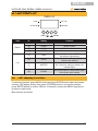
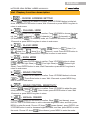
3. LED DISPLAY
DMX
MASTER
SLAVE
SOUND
DISPLAY
menu enter
Item N. Display Function
Button:
(1) MENU Enter the menu
(2) DOWN Next the menu
(3) UP Previous menu
(4) ENTER Enter the select function
Led:
(5) DMX
DMX mode,If received the DMX signal,
the indicator light ashing
(6) SLAVE
Slave mode,if received slave signal, the
indicator light ashing
(7) MASTER
Master mode, one machine or many in
test, There is a setting for master, the
indicator lights
(8) SOUND
In the sound active, if have sound signal,
the indicator lights ashing
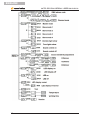
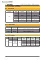
3.1. LED display function
To choose a function, press MENU button and press ENTER button enter the chosen
function, LED display strobe, then press UP/DOWN button to choose the function,
press ENTER button to conrm. Wait for 10 seconds or press the MENU long time to
go back to main mode.
Main function as follows:

14
ENGLISH
MTR-25-10W-RGBW User manual

15
ENGLISH
MTR-25-10W-RGBW User manual
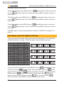
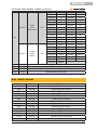
3.2. Display function description
1. - DMX512 Address Setting
Chose , press ENTER button to conrm. Press UP/DOWN button to initial ad-
dress, and press ENTER button to save, Wait 10seconds or press MENU long time to
return to main menu.
2. - Channel Mode
Choose , press ENTER button to conrm. Press UP/DOWN to choose the chan-
nel, like (1 channel) or (4 channels) or (5 channels) or
(25 channels) or (75 channels) mode, etc. Press ENTER button to save it. Wait
10seconds or press MENU long time to return to main menu.
3. - Slave mode
Choose , press ENTER button to enter (Master) or (slave 1) or
(slave 2) or (slave 3) or (slave 4) mode. Press ENTER button to
save. Wait 10seconds or press MENU long time to return to main menu.
4. - Show mode
Choose , press ENTER button to conrm. Press UP/DOWN button to chose
(One/Two Light Show) or (Four Light Show) or (Sixteen Light
Show). Press ENTER button to save, Wait 10seconds or press MENU long time to
return to main menu.
5. - Sound Control
Choose , press ENTER button to conrm. Press UP/DOWN button to choose
or .Press Enter button to save. Wait 10seconds or press MENU long
time to return to main menu.
6. - Sound control sensitivity
Choose , press ENTER button to conrm. Press UP/DOWN to adjust the sen-
sitivity value from to . After chosen, press ENTER button to save. Wait
10seconds or press MENU long time to return
7. - Manual dimmer
Choose , press ENTER button to conrm. Show (red dimmer), press
ENTER. Use UP/DOWN button to add or decrease brightness value, and then, press
MENU to enter the mode. Choose UP show (green dimmer), press ENTER, use
UP/DOWN button to add or decrease brightness value, and then, press MENU to enter
the mode. Choose UP show (blue dimmer), press MENU to enter the mode.

16
ENGLISH
MTR-25-10W-RGBW User manual
Wait 10seconds or press MENU long time to return to main menu.
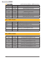
8. - LED display
Choose , press ENTER button to conrm. Press UP/DOWN button to choose
(light on) or (light off) mode. After chosen, press ENTER button to save.
Wait 10seconds or press MENU long time to return to main menu.
9. - LED display
Choose , press ENTER button to conrm. Press UP/DOWN button to choose
(display on) or (display off) mode. After chosen, press ENTER button to
save. Wait 10 seconds or press MENU long time to return to main menu.
10. - LED display inversion
Choose , press ENTER button to conrm, then enter the (inversion). After
chosen, press MENU to enter the mode. Wait 10seconds or press MENU long time to
return to main menu.
11. - Test
Press MENU button to , press ENTER button, the led display will strobe, the
light will run built in program, press MENU to back to main menu.
12. - Temperature
Press MENU button to , press ENTER button, the led display will show the
temperature, press MENU to back to main menu.
13. - Working time
Press MENU button to , press ENTER button, the led display could show the
working time, press MENU back to main menu.
14. - Version
Press MENU button to , press ENTER button, the display shows software ver-
sion, press MENU back to main menu.

17
ENGLISH
MTR-25-10W-RGBW User manual
4. DEVICE USE AND SETTING
4.1. 1pc use and display settings
Press MENU button to (master/slave mode), choose and conrm
(master mode), then press MENU button to (show mode), choose and conrm
(1 or 2pc device show mode). After 10 seconds or press MENU long time to
return to main menu.
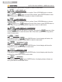
4.2. 4pcs use and display settings
Assemble the 4 modules following the instructions described in “2.2. Module Mechani-
cal Connection” on page 7. Then set one by one as below picture show.
First device setting: press MENU button to (master/slave mode). Choose and
conrm (master mode), then press MENU button to (show mode).
Choose and conrm (4pc device show mode). After 10 seconds or press MENU

18
ENGLISH
MTR-25-10W-RGBW User manual
long time to return to main menu.
Second device setting: press MENU button to (master/slave mode), choose and
conrm (slave2 mode). After 10seconds or press MENU long time to return to
main menu.
Third device setting: press MENU button to (master/slave mode), choose and
conrm (slave4 mode). After 10seconds or press MENU long time to return to
main menu.
Fourth device setting: press MENU button to (master/slave mode), choose and
conrm (slave3 mode) . After 10 seconds or press MENU long time to return to
main menu.
Use DMX cable to connect the 4pcs devices as shown on “DMX-512 Connection” on
page 10.
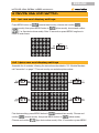
4.3. 16pcs use and display settings
Please mount the 16 modules following the instructions described in “2.2. Module Me-
chanical Connection” on page 7. Then set one by one as below picture show.
To set one device as master rstly, press MENU button to (master/slave mode).
Choose and conrm (master mode), then press MENU button to (show
mode). Choose and conrm (16pcs using effect), then the second device press
MENU button to (master/slave mode), choose and conrm (slave2
mode), the third device choose and conrm , then set one by one to .
After 10 seconds or press MENU long time to return to main menu.

19
ENGLISH
MTR-25-10W-RGBW User manual
Use DMX cable to connect the 16pcs devices as shown on “DMX-512 Connection” on
page 10.
4.4. LED Operation
LED Function
If you have a large-scale performance, mainly use computer software or dmx controller
to control lights, and you are worried will have one or more DMX signal cables dam-
aged to lead to the program run automatically, resulting in light run around. At this time,
you expect the lights automatically exterminate (black), then please following below
step to set.
Press MENU button to (led on), choose (led off), then press MENU but-
ton to choose (Standby function), after nished above action does not affect the
operation of the DMX control, when the DMX signal appears abnormal, the device will
jump to standby function automatically (black out).
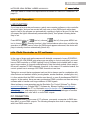
4.5. DMX Controller or PC software
In the case of large-scale performances with ledwalls composed of many SOUNDSA-
TION MTR-25-10W-RGBW units where you are willing to control each pixel, you must
have a DMX controller or a DMX Lighting Control Software (not included) able to man-
age a large number of channels simultaneously. Note that each module, when used in
this mode, requires 75 DMX channels; therefore, in the case of 16 modules ledwall, the
control system has to manage 1200 DMX channels at one time.
Taking into account that an equipment such as this is always used in combination with
other xtures and ambient effects (moving heads, smoke machines, strobe lights, etc.),
it is then evident that the DMX controller must have 4 or even 8 simultaneous DMX512
outputs. In the market, there are many professional DMX controllers as there are many
software able to handle such huge numbers of DMX signals.
About software, some examples may be Emulation Pro Control Software
®
by Elation
www.elationlight.com, Eclipse DMX™ Software by Blizzard Lighting www.blizzard-
lighting.com, Sulite Suite 2™ by Nicolaudie www.nicolaudie.com, Madrix 3 by Madrix
®
www.madrix.com, and many more. Just pay attention to choose packages or bundles
that offer DMX control units with 4 or more DMX outputs.
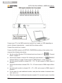
PC connection
As explained before, In the case of PC software, you needs a computer-to-DMX inter-
face with 2 or more DMX outputs. The following example show how to setup a system
with 8-out DMX control unit.

20
ENGLISH
MTR-25-10W-RGBW User manual
Connect your PC to the DMX control unit using a Cat-5 cable (or USB, depending on
control software characteristics - consult with the software seller).
Connect the control box to mains.
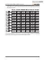
Connect the DMX outputs to all MTR-25-10W-RGBW according to the number of de-
vices and the following instructions:
f Set all modules We take 75CH channel mode as shown in “2. - Channel
Mode” on page 15
f Set the rst module to channel 001 following the instructions in “1. DMX512
Address Setting” on page 18 and connect to DMX Output 1 of the control unit
f Set the second module to channel 001 + 75 = 76 and connect to DMX output of
Module 1
f Set the third module to channel 076 + 75 = 151 and connect to DMX output of Mod-
ule 2
f Set the fourth module to channel 151 + 75 = 226, and connect to DMX output of
Module 2
f Do the same for each additional module, need plus the number of selected chan-
nels, and so on...
f When the number of additional channels exceeds 512, we need to pass to another
La pagina si sta caricando...
La pagina si sta caricando...
La pagina si sta caricando...
La pagina si sta caricando...
La pagina si sta caricando...
La pagina si sta caricando...
La pagina si sta caricando...
La pagina si sta caricando...
-
 1
1
-
 2
2
-
 3
3
-
 4
4
-
 5
5
-
 6
6
-
 7
7
-
 8
8
-
 9
9
-
 10
10
-
 11
11
-
 12
12
-
 13
13
-
 14
14
-
 15
15
-
 16
16
-
 17
17
-
 18
18
-
 19
19
-
 20
20
-
 21
21
-
 22
22
-
 23
23
-
 24
24
-
 25
25
-
 26
26
-
 27
27
-
 28
28


Soundstream MTR-25-10W-RGBW Manuale utente
- Categoria
- Stroboscopi
- Tipo
- Manuale utente
in altre lingue
Altri documenti
-
soundsation 4LEDKIT-DJ Manuale utente
-
PROEL PLLED125 Manuale utente
-
Elation PROTEUS RAYZOR 760 Manuale utente
-
Elation PROTEUS RAYZOR 760 Manuale utente
-
-
-
ProLights SMARTBATIP Manuale utente
-
-
-