Audio Technica AT-ONE Istruzioni per l'uso
- Categoria
- Microfoni
- Tipo
- Istruzioni per l'uso

UHF Wireless Microphone System
Installation and Operation

Contents
Introduction
- Introduction 1
- Safety 1
System Functions
- Receiver Functions 2-3
- Handheld Transmitter Functions 4
- Bodypack Transmitter Functions 5
- Battery Status 6
System Operation
- System Setup 6
- Receiver Operation 7
- Transmitter Operation 8
- Squelch 9
- Frequencies 9
- Troubleshooting 10
- Rack Mount Setup 11
Specifications
- Overall Specification 12
- Receiver Specification 12
- Bodypack Transmitter Specification 13
- Handheld Transmitter Specification 13
Compliance
- WEEE Regulations 14
- Declaration of Compliance 15

Introduction
Introduction
Thank you for purchasing this Audio-Technica product. This PLL synthesized wireless microphone
system operates in the UHF band frequency, with two groups of four frequencies. Please read this
manual carefully before operating the AT-One system. This manual covers the function and operation of
the wireless microphone system.
Safety
- To prevent fire or shock hazard, do not expose this appliance to rain or moisture
- To prevent fire, do not cover the ventilation of the apparatus with newspaper, tablecloths, etc.
- Do not expose this apparatus to drips or splashes
- Do not place any objects filled with liquids, such as vases, on the apparatus
- Do not install this apparatus in a confined space such as a bookcase or similar unit
- The aparatus should be located close enough to the AC outlet so that you can easily grasp the
AC adapter at any time. In case of emergency, disconnect the AC adapter quickly.
- Danger of explosion if battery is incorrectly replaced. Replace only with the same or equivalent
type.
- If the transmitter is not in use for an extended period, remove the batteries to avoid damage
- Do not dispose of used batteries with domestic rubbish. Be sure to dispose of batteries in
accordance with your local waste disposal rules.
- When disposing of the equipment, remove the batteries, separate the case, circuit boards and
cables, and dispose of all components in accordance with local waste disposal rules.
The circuits inside the receiver and transmitter have been precisely adjusted for optimum performance
and compliance with government regulations. Do not attempt to open the receiver or transmitter. To do
so will void the warranty, and may cause improper operation.

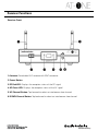
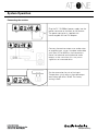
Receiver Functions
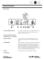
Receiver Front:
1. Antenna: Detachable UHF antenna with BNC connector
2. Power Button
3. RF Red LED: Displays the reception status of the RF signal
4. AF Green LED: Displays the reception status of the AF signal
5. UP Channel Button: Tap forward to select an interference free channel
6. DOWN Channel Button: Tap backward to select an interference free channel

Receiver Functions
Receiver Rear:
1. Antenna BNC Receptacle: This provides a connection to the supplied antennas or to
coaxial cable used with an antenna divider, antenna
booster or remote antennas
2. Balanced XLR Audio Output
3. Unbalanced 1/4” Jack Output
4. Mic/Line Switch: Use this to adjust the audio output of the wireless
microphone system for mic level (-20dB) or line-level
(0dB)
5. SQ (Squelch): Turn the squelch to the lowest possible setting (counter
clockwise) to eliminate any interfering signals. In RF
crowded environments (other wireless microphones, LTE,
etc.) it can be required to increase the squelch level
(clock wise) to block out unwanted noise. Please note
that this will reduce the operating distance of the system,
so always seek the lowest possible setting.
6. DC IN: DC input connector for the supplied AC adapter
7. Cable Strain

Transmitter Functions
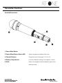
Handheld Transmitter:
1. Power/Mute Button
2. Power/Mute/Battery Status LED Indicates the power/mute/battery level status
3. Channel Selector: Change the channel setting from 11-14 or 21-24
4. Battery Compartment: Insert two AA batteries making sure the polarity is correct
5. Grille: Protects the microphone capsule and protects against wind
and breath sound

Transmitter Functions
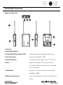
Bodypack Transmitter:
1. Antenna
2. Power/Mute Button
3. Power/Mute/Battery Status LED: Indicates the power/mute/battery level status
4. Input Connector: 4-pin locking connector (HRS)
5. Channel Selector: Change the channel setting from 11-14 or 21-24
6. Gain: Rotary control adjusts the sensitivity of the
transmitter’s audio to the level of the connected
mic or instrument
7. 10dB Switch: Activate this switch to attenuate the signal by
an additional 10dB.
8. Battery Compartment: Insert two AA batteries making sure the polarity is
correct

Transmitter Functions
LED Status
Green Ready
Red Muted
Green Flashing On, low battery
Red Flashing Muted, low battery
No Light No power
Power/Battery Status LED
:
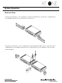
System Operation
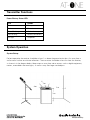
System Setup:
For best operation the receiver should be at least 1 m above the ground and at least 1m away from a
wall or metal surface to minimize reflections. The transmitter should be at least 2m from the receiver,
as shown in in the diagram below. Keep antennas away from noise sources such as digital equipment,
motors, automobiles and neon lights, as well as away from large metal objects.
2 m
1 m
1 m
1 m

System Operation
Connecting the receiver:
Plug the DC 12V 500mA power supply into the
power connector on the back of the receiver.
The power connector is supplied with
interchangable UK and EU adaptors.
Connect the receiver output to an audio mixer
or amplifier input, using a standard audio cable
with 3-pin XLR or 6.35mm Jack connectors.
Never use balanced and unbalanced audio
outputs at the same time, this may cause
signal loss or increased noise.
Set the attenuation for mic or line input.
Two-position switch adjusts the audio output
attenuation to 0 dB or -20 dB. The factory
setting is 0 dB.
Line Mic

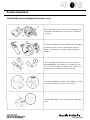
System Operation
Handheld Microphone/Bodypack Transmitter set up:
Open the battery cover and insert AA batteries into
the battery compartment making sure the polarity
is correct.
Unscrew the bottom of the handheld mic and open
the battery cover to insert AA batteries into the
battery compartment, making sure the polarity is
correct.
Press and hold the power button on the micro-
phone/bodypack transmitter for 4 seconds to turn
on. If the LED remains flashing after 4 seconds it is
indicating that the battery is low on power.
Use the included key to adjust the frequency of the
transmitter to be the same as the receiver.
Use the 0dB/-10dB switch to adjust the audio input
level.
0dB -10dB

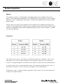
System Operation
Frequencies
Group 1 Group 2
Channel Frequency [MHz] Channel Frequency [MHz]
11 863.300 21 863.700
12 864.300 22 864.700
13 824.875 23 824.400
14 830.850 24 828.650
Each AT-One system comes with Group 1 and Group 2 frequencies available as shown in the
table above. The system has been designed in these groups to allow you to use up to four
channels in one group together, interference free (subject to national licensing and regulations).
In an environment with two separated event areas (two seaparate conference rooms e.g.) it is
possible to use Group 1 in the first location and Group 2 in the second location.
All frequency usage is subject to National regulations, please check with your local Goverment
authority for usage restrictions.
Squelch
The squelch function is used to adjust the audio output level to suppress the noise
levels. If you experience interference in RF spoiled areas (e.g. areas with a lot of mobile
phones) or cross talk between transmitters, increase the squelch level until the interfer-
ence is gone.
Please note that increasing the squelch level will decrease the operating range of the
system. If the squelch level is high, you may need to move the transmitter closer to the
receiver. To experience the maximum operating range, make sure the squelch is turned
to the lowest position.

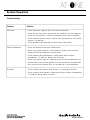
System Operation
Troubleshooting
Problem Solution
No Sound - Check the power supply of the transmitter and receiver
- Check that the transmitter and receiver are tuned to the same frequency
- Check that the receiver is correctly connected to the mixer or amplifier
- Check whether the transmitter is too far from the receiver or the Squelch
control is set too high
- Check for obstuctions between the transmitter and receiver
Sound Interference - Check the location of the aerial for obstacles
- When using two or more sets simultaneously, make sure the chosen
frequencies do not interefere with each other
- Check whether the intereference is coming from other wireless
microphones, TV, radio etc. being used in the area
- When using two or more sets keep the minimum distance between the
receiver and the transmitter greather than 2m and the distance between
the two transmitters greater than 1m to avoid cross talk interference
Distortion - Check whether the receiver volume level is set too high or too low
- Check whether the distortion is coming from other wireless microphones,
TV, radio etc. being used in the area

System Operation
Rackmount Setup:
To connect two receivers in a 19”standard rack using the optional AT8677 rack kit, attach the short L
shaped brackets to the opposite end of each unit, and connect the units together using two metal
connecting plates.
To mount the receiver in a 19”standard rack using the included rack kit, attach the L shaped brackets
to the opposite end of the unit and mount in the rack unit.

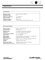
Specifications
Overall System
Frequency range: 824 - 831 MHz, 863 - 865 MHz
Modulation mode: FM
Number of frequencies: 2 x 4 frequencies
Operating range: 60m, typical
Frequency response: 60 HZ - 16 kHz
Frequency stability: +/- 0.005%, phase lock loop frequency control
Receiver Specifications
Receiver system: Antenna switching diversity
Image rejection: 55 dB minimum
Dynamic range: HH: 108 dB BP: 103 dB (@ max deviation)
Sensitivity: 10 dBµV (S/N 60 dB @ 20 kHz deviation)
Total Harmonic Distortion: <1% - 20 kHz deviation @ 1 kHz
Level control: Mic / Line (0/-20dB)
Antenna Input: BNC type, 50 ohms - BIAS voltage 12 V DC 100mA each
Audio Output: Unbalanced -2dBV, Balanced +4dBV
Output connectors: Unbalanced: 6.3 mm mono jack, Balanced: XLRM-type
Dimensions: 200 mm x 42 mm x 122 mm (W x H x D)
Weight: 418 g without accessories
Accessories included: AC Adapter, Antennas, Rack mount adapter
Optional System Accessory: AT8677 Dual rack mount kit

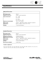
Specifications
Body-Pack Transmitter
RF Output power: 10 mW
Spurious Emissions: Follows national regulations
Input connections: Pin 1: GND
Pin 2: INST
Pin 3: Mic
Pin 4: DC Bias + 10 V
Batteries (not included): Two 1.5 V AA alkaline
Battery Life: 10 hours - depending on battery type and use pattern
Dimensions: 66 mm x 98 mm x 22 mm (W x H x D)
Weight: 71 g without batteries
Handheld Transmitter
RF Output power: 10 mW
Spurious Emissions: Follows national regulations
Microphone Element: Cardioid Condenser
Batteries (not included): Two 1.5 V AA alkaline
Battery Life: 10 hours - depending on battery type and use pattern
Dimensions: 268 mm long - 52 mm (diameter)
Weight: 277 g without batteries
Accessories included: Stand clamp
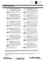
Product compliant in:
AUT, BEL, BGR, HRV, CYP, CZE, DNK, EST, FIN, FRA, DEU, GRC, HUN, IRL, ITA, LVA, LTU,
LUX, MLT, NLD, POL, PRT, ROU, SVK, ESP, SWE, GBR

WEEE Regulations

Declaration of Compliance
BG С настоящото, Audio-technica Corp. декларира, че ATW-T1F, ATW-T3F и ATW-R1F са произведени в съответствие с Директива 1999/5/EC. Пълния текст на Декларацията за
съответствие, може да се намери на следния интернет адрес: eu.audio-technica.com/doc
HR Ovime Audio-Technica izjavljuje da su ATW-T1F, ATW-T3F i ATW-R1F u skladu s Direktivom 1999/5/EC. Puni tekst izjave EU o sukladnosti dostupan je na sljedećoj internet adresi:
eu.audio-technica.com/doc
CZ Tímto Audio-Technica Corporation prohlašuje, že ATW-T1F, ATW-T3F a ATW-R1F jsou v souladu se směrnicí 1999/5/EC. Úplné znění EU prohlášení o shodě je k dispozici na této
internetové adrese: eu.audio-technica.com/doc
DK Herved erklærer Audio-Technica Corp. at ATW-T1F, ATW-T3F og ATW-R1F er i overensstemmelse med direktiv 1999/5/ EC. Den fulde ordlyd af EU-overensstemmelseser
klæringen er tilgængelig på følgende internetadresse: eu.audio-technica.com/doc
NL Hierbij verklaart Audio-Technica Corp. dat ATW-T1F, ATW-T3F en ATW-R1F in overeenstemming zijn met Richtlijn 1999/5/EC. De volledige tekst van EU Conformiteitsverklaring
is beschikbaar op het volgende internet adres: eu.audio-technica.com/doc
GB Hereby, Audio-Technica Corp. declares that ATW-T1F, ATW-T3F and ATW-R1F are in compliance with Directive 1999/5/EC. The full text of the EU declaration of conformity is
available at the following internet address: eu.audio-technica.com/doc
EE Käesolevaga Audio-Technica Corp., kinnitab, et ATW-T1F, ATW-T3F ja ATW-R1F on vastavuses 1999/5/EC direktiiviga. EU vastavusdeklaratsiooni terviktekst on kättesaadav
järgmisel Interneti-aadressil: eu.audio-technica.com/doc
FI Me, Audio-Technica Corp., vakuutamme yksinomaan omalla vastuulla että ATW-T1F, ATW-T3F ja ATW-R1F täyttävät direktiivin 1999/5/EC. EU-vaatimustenmukaisuusvakuutus on
luettavissa kokonaisuudessaan osoitteessa: eu.audio-technica.com/doc
FR Par la présente, Audio-Technica Corp. Déclare que ATW-T1F, ATW-T3F et ATW-R1F sont conformes à la Directive 1999/5/EC. Le texte complet de la déclaration de conformité
est disponible sur le site Internet suivant: eu.audio-technica.com/doc
DE Hiermit erklärt die Audio-Technica Corp., dass ATW-T1F, ATW-T3F und ATW-R1F den Richtlinien 1999/5/EC entsprechen. Den kompletten Wortlaut der EU-Konformitätserklärung
finden Sie unter folgender Internet-Adresse: eu.audio-technica.com/doc
GR Με το παρών , η Audio Technica Corp., δηλώνει ότι τα ATW-T1F , ATW-T3F και ATW-R1F συμφωνούν με την οδηγία 1999/5/EC . Το πλήρες κείμενο της οδηγίας της EU ( ∆ήλωση
Συμμόρφωσης ) , είναι διαθέσιμο στην παρακάτω διεύθυνση διαδικτίου: eu.audio-technica.com/doc
HU Jelen Nyilatkozattal az Audio-Technica Corporation kijelenti, hogy az ATW-T1F, ATW-T3F és ATW-R1F megfelelnek a 1999/5/EC Irányelvnek. Az EU Megfelelőségi Nyilatkozat
teljes szövege az alábbí internetcímen érhető el: eu.audio-technica.com/doc
IE Le seo, dearbhaíonn Audio-Technica Corp. go bhfuil ATW-T1F, ATW-T3F agus ATW-R1F i gcomhréir le treoir 1999/5/EC. Tá an téasc iomlán dearbhú comhréireachta An Aontais
Eorpaigh le fáil ag an seoladh idirlín seo a leanas: eu.audio-technica.com/doc
IT Con la presente, Audio-Technica Corp. dichiara che ATW-T1F, ATW-T3F e ATW-R1F sono conformi alla direttiva 1999/5/EC. Il testo completo della dichiarazione di conformità EU
è disponibile al seguente indirizzo internet: eu.audio-technica.com/doc
LV Ar šo Audio-Technica Corporation deklarē, ka ATW-T1F, ATW-T3F un ATW-R1F atbilst Direktīvai 1999/5/EC. Pilns ES Atbilstības Deklarācijas teksts ir pieejams sekojošā Interneta
adresē: eu.audio-technica.com/doc
LT Šiuo dokumentu, Audio-Technica korporacija pareiškia, kad ATW-T1F, ATW-T3F ir ATW-R1F atitinka direktyvą 1999/5/EC. Pilną ES atitikties deklaracijos tekstą galima rasti šiuo
internetiniu adresu: eu.audio-technica.com/doc
MT Il-Korporazzjoni Audio-Technica hawn tiddikjara li ATW-T1F, ATW-T3F, ATW-R1F, huma konformi mad-Direttiva 1999/5/EC. Dan id-dokument tad-di rettiva ta' konformita mill EU
jinstab f'dan l-indirizz tal-internet: eu.audio-technica.com/doc
PL Niniejszym, firma Audio-Technica, oświadcza, że ATW-T1F, ATW-T3F, ATW-R1F są zgodne z dyrektywą 1999/5/EC. Pełny tekst deklaracji zgodności EU jest dostępny pod następu-
jącym adresem internetowym: eu.audio-technica.com/doc
PT Pela presente, Audio-Technica Corp. declara que ATW-T1F, ATW-T3F e ATW-R1F cumprem com a Diretiva 1999/5/EC. O texto completo da declaração de conformidade da UE
está disponível no seguinte endereço de Internet: eu.audio-technica.com/doc
RO Prin prezenta declarație Audio-Technica Corporation confirmă, că produsele ATW-T1F, ATW-T3F și ATW-R1F sunt conforme cu directivele 1999/5/EC. Declarația de Conformitate
EUcompletă poate fi accesată prin adresa următoare: eu.audio-technica.com/doc
SK Týmto spoločnosť Audio-Technica Corp. potvrdzuje, že ATW-T1F, ATW-T3F a ATW-R1F sú v súlade s Nariadením EU č. 1999/5/EC. Úplné znenie EU vyhláse nia o zhode je
dostupné na nasledujúcej internetovej adrese: eu.audio-technica.com/doc
SI S tem Audio-Technica Corp., izjavlja, da so ATW-T1F, ATW-T3F in ATW-R1F v skladu z Direktivo 1999/5/EC. Celotno besedilo izjave EU o skladnosti je na voljo na naslednjem
spletnem naslovu: eu.audio-technica.com/doc
ES Por la presente, Audio-Technica Corp. declara que ATW-T1F, ATW-T3F y ATW-R1F cumplen con la Directiva 1999/5/EC. El texto completo de la declaración de conformidad de
la UE está disponible en la siguiente dirección de Internet: eu.audio-technica.com/doc
SE Härmed försäkrar Audio-Technica Corp., att ATW-T1F, ATW-T3F och ATW-R1F överstämmer med direktiv 1999/5/EC. Den fullständiga texten av EU direktiv finner ni på följande
Internetadress: eu.audio-technica.com/doc
A full copy of the statement of conformity may be obtained from: eu.audio-technica.com/doc
CAUTION! Electrical shock can result from removal of the receiver cover.
Refer servicing to qualified service personnel.
• To prevent fire or shock hazard, do not expose this appliance to rain or
moisture.
• To prevent fire, do not place any naked flame sources (such as lighted
candles) on the apparatus.
• To prevent fire do not cover the ventilation of the apparatus with
newspaper, tableclothes, curtains etc.
• Do not expose this apparatus to drips or splashes.
• Do not place any objects filled with liquids, such as vases, on the
apparatus.
• Do not install this apparatus in a confined space such as a bookcase or
similar unit.
• The apparatus should be placed close enough to the AC outlet so that you
can easily grasp the AC adaptor at any time.
• In case of emergency disconnect the AC adaptor quickly.
• Danger of explosion if battery incorrectly replaced. Replace only with the
same or equivalent type.
• Always consider environmental issues and follow your local regulations
when disposing of batteries. Do not expose batteries to excessive heat.
The circuits inside the receiver and transmitter have been precisely adjusted
for optimum performance and compliance with federal regulations. Do not
attempt to open the receiver or transmitter. To do so will void the warranty,
and may cause improper operation.
Notice to individuals with implanted cardiac pacemakers or AICD devices:
Any source of RF (Radio Frequency) energy may interfere with normal
operation of the implanted device. All microphones have low-power transmitters
(less than 0.05 watts output) which are unlikely to cause difficulty, especially if
they are at least a few inches away.
However, since a body-pack transmitter typically is placed against the body, we
suggest attaching it to a belt rather than a shirt pocket where it may be
immediately adjacent to the medical device.
Note also that any medical device disruption will cease when the RF
transmitting source is turned off. Please contact your physician or medical device
provider if you have any questions, or experience any problems with the use of
this or any other RF equipment.
Please note that wireless frequencies are shared with other radio services.
If you need assistance with operation or frequency selection please contact
your dealer or Audio-Technica. Extensive wireless information is also available
at www.audio-technica.com

Audio-Technica Ltd
Technica House
Unit 5 Millenium Way
Leeds
LS11 5AL
UNITED KINGDOM
Tel: +44(0) 113 2771441
Fax: +44(0) 113 2704836
Audio-Technica SAS
11 Rue des Pyramides
75001 Paris
FRANCE
Tel: +33(0) 1 43 728282
Fax: +33(0) 1 43 726070
Audio-Technica Niederlassung Deutschland
Lorenz-Schott-Str. 5
D-55252 Mainz-Kastel
GERMANY
Tel: +49(0) 6134 25734 0
Fax: +49(0) 6134 25734 50
Audio-Technica Central Europe Ltd
Fogado u 3
H-1107 Budapest
HUNGARY
Tel: +36(0) 433 34 08
Fax: +36(0) 431 90 06
-
 1
1
-
 2
2
-
 3
3
-
 4
4
-
 5
5
-
 6
6
-
 7
7
-
 8
8
-
 9
9
-
 10
10
-
 11
11
-
 12
12
-
 13
13
-
 14
14
-
 15
15
-
 16
16
-
 17
17
-
 18
18


Audio Technica AT-ONE Istruzioni per l'uso
- Categoria
- Microfoni
- Tipo
- Istruzioni per l'uso
in altre lingue
Documenti correlati
Altri documenti
-
Audio-Technica ATW-R1820 Manuale utente
-
 FITNESS AUDIO SDR-5716 Istruzioni per l'uso
-
soundsation POCKETMIC U16HH-A1 Manuale utente
-
RTS Tr-34 Manuale utente
-
Led Lenser 6005 Operating Instructions Manual
-
Panasonic WVCP160 Istruzioni per l'uso
-
Hitachi ATW-RTU-05 Istruzioni per l'uso
-
Samsung SCC-B2305P Manuale utente
-
