
wireless
wireless
wireless
wireless
wireless
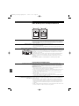
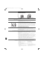
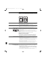
1800 Series
Camera-mount UHF Wireless
Microphone Systems (dual-channel)
AT W - R
1820
Dual Channel Receiver
AT W -T
1801
UniPak™ Body-pack Transmitter
AT W -T
1802
Plug-on Transmitter
Installation and Operation
Installation et Utilisation
Installation und Betrieb
Instalación y Manejo
Installazione ed Utilizzazione
Instalação e Funcionamento
Installatie en Bediening
EN
FR
DE
ES
IT
PT
NE
!
0470
OM1800Ser_dual(europ).qxd:Layout 1 1/10/07 14:35 Page 1

This device complies with the European R&TTE directive 1999/05/EC.
Operation is subject to the condition that this device does not cause harmful interference.
Notice to individuals with implanted cardiac pacemakers or AICD devices:
Any source of RF (radio frequency) energy may interfere with normal functioning of the implanted device. All wireless microphones have
low-power transmitters (less than 0.05 watts output) which are unlikely to cause difficulty, especially if they are at least a few inches away.
However, since a ”body-pack” mic transmitter typically is placed against the body, we suggest attaching it at the belt, rather than in a shirt pocket where
it may be immediately adjacent to the medical device. Note also that any medical-device disruption will cease when the RF transmitting source is turned
off. Please contact your physician or medical-device provider if you have any questions, or experience any problems with the use of this or any other
RF equipment.
CAUTION! The circuits inside the receiver and transmitter have been precisely adjusted for optimum performance and compliance with national
regulations. Do not attempt to open the receiver or transmitter. To do so will void the warranty, and may cause improper operation.
Warning: To prevent fire or shock hazard, do not expose this appliance to rain or moisture.
About RF Interference
Please note that wireless frequencies are shared with other radio services.
Please make certain, that you follow the national regulations of the country where you are planning to use the system.
If you need help with operation or frequency selection, please contact your local dealer or Audio-Technica. Extensive wireless information also is
available at www.audio-technica.com.
Contents
Components and System Configurations 3
System Features 4
Quick Overview of System Operation 5
Receiver Controls 6
Operating the Receiver 8
Transmitter Controls 11
Operating the Transmitter 12
Tips for Best Results 14
Available Accessories 14
Scanplans for 1800 Series 15
Specifications 16
Warranty 17
2
E
N
OM1800Ser_dual(europ).qxd:Layout 1 1/10/07 14:35 Page 2

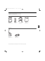
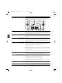
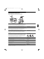
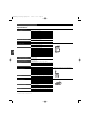
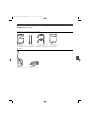
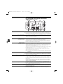
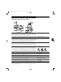
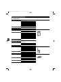
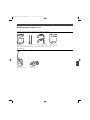
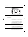
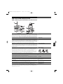
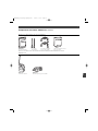
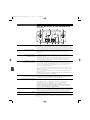
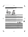
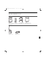
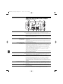
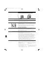
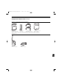
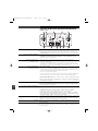
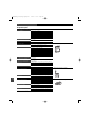
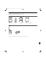
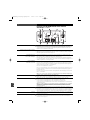
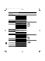
1800 Series Components (dual-channel)
Receiver and Included Components/Accessories
ATW-R1820
Dual-channel receiver
Two detachable
antennas
Two 45 cm output cables,
TA3F to XLRM
Pouch with belt clip
(holds receiver)
Transmitters
AT W - T 18 0 1
UniPak™ transmitter
ATW-T1802
Plug-on transmitter
Note: All model numbers have an additional letter at the end to indicate frequency band.
E
N
3
OM1800Ser_dual(europ).qxd:Layout 1 1/10/07 14:35 Page 3

System Features (dual-channel)
• Two completely independent receiver channels in a single unit, for simultaneous
operation of two microphones
• Extremely compact receiver easy to mount on a camera with included Velcro-type
fastener
• UHF reception with up to 996 frequencies selectable in 25kHz steps
• Automatic frequency scanning for easy selection of open channels
• Tone Lock™ squelch system eliminates interference when transmitter is off
• Two independent balanced outputs (you can assign function of each,
independently)
• Headphone monitor output with independent level control
• Battery fuel-level indicator.
• Soft-touch controls for easy frequency selection
• True Diversity operation for freedom from dropouts
• LCD frequency and battery status display with backlight
• Antenna and AF Peak LED indicators
• Easy, user-friendly operation
• Clear, natural sound quality
• System components of the 1800 Series and 3000 Series Wireless Systems can be
used interchangeably*
*Note: The 1800 Series offers UHF Wireless operation frequencies in 25KHz step, therefore
the 1800 transmitters and receivers feature up to 996 selectable frequencies (depending on
the frequency band).
The components of the 1800 Series and 3000 Series are compatible, however considering
that transmitters and receivers of the 3000 Series operate only on 200 programmed
frequencies, a system composed of mixed element from 1800 Series and 3000 Series will
only operate on the 200 pre-programmed frequencies of the 3000 element.
Be certain to set each transmitter receiver pair to identical frequencies.
4
E
N
OM1800Ser_dual(europ).qxd:Layout 1 1/10/07 14:35 Page 4

Quick Overview of System Operation
Thank you for purchasing this Audio-Technica 1800 Series Dual-channel Camera-mount UHF
Wireless Microphone System. All 1800 Series systems are designed primarily to be used with
video cameras, with the ATW-R1820 dual-channel receiver mounted on a camera and
connected to the camera's audio input; the systems may also be used with other components
equipped with microphone-level input(s).
This system is equipped with a dual receiver, which consists of two completely independent
receiver channels in a single unit, for simultaneous operation of two microphones.
First, insert batteries (
see Battery Installation, page 8
). Note: The ATW-R1820 dual-channel
receiver also functions without batteries if connected to an external power supply
(12V DC source, 500 mA nominal current, not included).
Next, attach the antennas to the antenna input jacks, and mount the ATW-R1820 dual-channel
receiver to your camera (mounting hardware not included); or use the included pouch with belt
clip to attach the ATW-R1820 to your belt. Connect the output cable(s) to the ATW-R1820 and your
video camera (and/or audio mixer). (
See Output A, Output B, and Output Select Switch, page 7.
)
Turn the ATW-R1820 Power Switch on. Choose ”1” to activate only Receiver Channel 1 and Output
A (Power/Peak LED 1 should light red); this option will increase useable battery life. Choose ”Both”
to activate both receiver channels and both outputs (Power/Peak LEDs 1 and 2 should light red).
(
See Power Switch with four positions: External, Off, 1, Both, page 6.
)
Select a frequency for Receiver Channel 1 and Receiver Channel 2. (
See Selecting Frequencies on
your Receiver, page 8.
)
NOTE: Receiver Channel 1 and Receiver Channel 2 must be set to different frequencies to
avoid interference. Transmitter-Receiver pairs must be set to identical frequencies: set
Transmitter 1 to the same frequency as Receiver Channel 1; set Transmitter 2 to the same
frequency as Receiver Channel 2.
If your system is equipped with a UniPak™ Body-pack Transmitter : Plug your wireless essential
microphone (not included) into the UniPak body-pack transmitter(s). Turn the power on, select a
frequency and choose other settings. (
See Operating the Transmitter, page 12.
)
If your system is equipped with a Plug-on Transmitter:
Attach a microphone (dynamic or condenser) to the plug-on transmitter’s input connector
(
see Microphone Input, page 11)
. The transmitter provides power to condenser microphones rated
to operate on 12V phantom power or less. Turn the power on, select a frequency and choose
other settings. (
See Operating the Transmitter, page 12.
)
5
E
N
OM1800Ser_dual(europ).qxd:Layout 1 1/10/07 14:35 Page 5

6
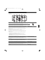
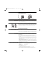
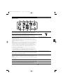
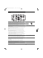
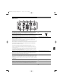
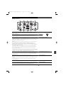
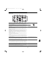
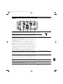
ATW-R1820 Dual-channel Receiver Controls (front
panel)
Liquid Crystal Display shows battery status and frequency settings. (Use the Dual-channel
Control Switch (6) to select frequencies for Receiver Channel 1 and Receiver Channel 2;
in Hold position, only Receiver Channel 1 frequency appears in LCD.) Battery meter is only active
when Dual-channel Control Switch is in the Hold position.
BNC-type antenna connectors. Antennas A & B (split internally) both provide signals for Receiver
Channel 1 and Receiver Channel 2. Attach the antennas to the antenna input jacks. Make certain
that during operation there is a clear open-air path between the receiver antennas and the
transmitters.
True Diversity operation: two antennas feed two completely independent RF sections on the
same frequency for each receiver; automatic logic circuitry selects the superior signal.
Diversity Indicator 1 indicates which tuner has the better reception and is in operation for
Receiver Channel 1; Diversity Indicator 2 indicates which tuner has the better reception and is in
operation for Receiver Channel 2.
Turns the unit on and off.
Choose ”Ext”, if the unit is connected to an external power supply (12V DC source, 500 mA
nominal current, not included). In ”Ext” position, both receiver channels and both outputs are
activated (indicated by illumination of Power/Peak LEDs 1 and 2).
Choose ”Off” to turn the unit off.
Choose ”1” to activate only a single receiver channel (Receiver Channel 1/Output A, indicated by the
illumination of Power/Peak LED 1). This conserves energy if you are only using one audio channel.
Choose ”Both” to activate both receiver channels and both outputs (indicated by illumination of
Power/Peak LEDs 1 and 2).
Note: Selected receiver will be muted unless Dual-channel Control Switch (6) is in Hold position.
Indicates which receiver channel(s) is (are) in operation. Also indicates receiver overload by
turning off; too much signal will cause blinking LED (off during peaks). To correct overload, adjust
audio gain on transmitter. (
See Audio Input Level (Gain) Adjustments, page 13.
)
This switch allows you to use the single LCD window to control each of the two receiver
channels separately.
To set frequency for Receiver Channel 1, switch to 1 (left position).
To set frequency for Receiver Channel 2, switch to 2 (right position).
To lock settings and operate unit, switch to Hold (centre position).
Note: Receiver Channel 1 is muted when switch is at 1; Receiver Channel 2 is muted when
switch is at 2; both channels un-mute when switch is at Hold.
This LED is red when switch is in position 1, indicating muted operation for Receiver Channel 1. It
is also red when switch is in position 2, indicating muted operation for Receiver Channel 2. LED
turns green in Hold position, indicating unit is ready for operation.
Use with the Dual-channel Control Switch and Up/Down arrows to choose operating frequencies
manually or automatically (using your choice of automatic scan groups).
Press Up or Down arrows, in conjunction with the Set button, to choose operating frequencies
manually or automatically (using your choice of automatic scan groups).
LCD
Antenna Input Jacks
Diversity Indicators
for each antenna
for each receiver
Power Switch
with four positions:
External, Off, 1, Both
Power/Peak LED
Dual-channel Control Switch
with three positions: 1, Hold, 2
Dual-channel Control LED
Set
Up/Down Arrows
1
2
3
4
5
6
7
8
9
2
3
1 7
2
3 4
5
6
9
8
E
N
OM1800Ser_dual(europ).qxd:Layout 1 1/10/07 14:35 Page 6

7
Output A
Output B
Output Select Switch
Receiver Level Controls (1 and 2)
Monitor Select Switch
Monitor Level Control
DC Input
Monitor Output
(rear panel)
Balanced Audio Output Jack: TA3M-type connector. Pin 1: ground (shield); Pin 2: ”audio +”;
Pin 3: ”audio -”. Use the included TA3M to XLRM interface cable to connect the receiver output
to a balanced microphone-level input on a camera, mixer or integrated amplifier.
Balanced Audio Output Jack: TA3M-type connector. Pin 1: ground (shield); Pin 2: ”audio +”;
Pin 3: ”audio -”. Use the included TA3M to XLRM interface cable to connect the receiver output
to a balanced microphone-level input on a camera, mixer or integrated amplifier.
The rear panel provides two balanced audio outputs (Outputs A & B). The unit is equipped with
an output select switch that assigns a signal to each of the audio outputs, as follows:
Output A (left) can be assigned either Receiver Channel 1 or Mix. (Mix = Ch. 1 and Ch. 2
signals mixed together. The relative levels of each signal can be adjusted using the individual
receiver level controls.)
Output B (right) can be assigned either Receiver Channel 1, Receiver Channel 2, or Mix.
Note: Output B is not active when Power Switch is in ”1” position.
Typical configuration: Output A is assigned Channel 1; Output B is assigned Channel 2, feeding
individual channels in a mixer or camera. Many other options are available, providing much
flexibility. For instance:
• If your camera doesn’t accept two inputs, you can sum the signal from both transmitters
in Output A and connect this mixed signal to your camera.
• You can connect Output A (mixed signal) to a camera, and Output B (mixed signal)
to an audio mixer.
• When using the unit with a single transmitter with both outputs active (Power Switch set
at Both), Output A can be used to feed a camera, while Output B can feed an audio mixer
(both with identical signals from Receiver Channel 1).
The signal levels of each receiver signal (Receiver Channel 1 and Receiver Channel 2) may
be adjusted using these controls. When the outputs are assigned to a single receiver signal,
these controls will adjust the output level. (Turn clockwise to increase output level.) When the
outputs are assigned to Mix, these controls adjust the relative levels between the
receiver signals.
This switch assigns a signal to the monitor headphone output.
• Choose 1 (left position) to hear Channel 1 in both ears (mono signal, stereo output);
• Choose 2 (right position) to hear Channel 2 in both ears (mono signal, stereo output);
• Choose OUT (middle position), to hear Output A in the left ear, and Output B in the right ear.
The level control (volume control) for headphones is independent of other level controls.
Turn to the right to increase the volume.
You may connect the unit to an external power supply (12V DC source, 500 mA nominal
current, not included). In this case, move the Power Switch to the ”Ext” position; both receiver
channels are activated (indicated by illumination of Power/Peak LEDs 1 and 2).
1
/4” TRS jack.
10
17
14 11
16 13
15
10
11
12
5
6
13
14
15
16
17
13
12
12
PIN 1 PIN 3
PIN 2
E
N
OM1800Ser_dual(europ).qxd:Layout 1 1/10/07 14:35 Page 7

8
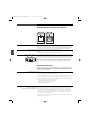
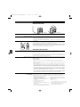
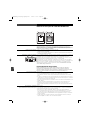
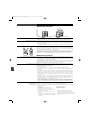
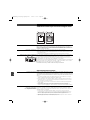
ATW-R1820 Dual-channel Receiver Batteries
Each ATW-R1820 dual-channel receiver uses six 1.5V AA batteries, not included. Alkaline type is
recommended. Always replace all batteries. Make certain the receiver power is Off before
replacing batteries. Note: The ATW-R1820 receiver also functions without batteries if connected
to an external power supply (12V DC source, 500 mA nominal current, not included).
1. Open the battery compartment door by pushing the catch back.
2. Observe correct polarity as marked and carefully insert six fresh 1.5V AA alkaline batteries
(
see above
).
3. Replace the door, making certain the latch clicks securely in place.
After the batteries are installed, turn the power on by moving the Power Switch to either the 1 or
Both position. The small red power-on LED(s) (
see(
a
) at left
) should light (red light at 1 if Power
Switch is in position 1; red light at 1 and 2 if Power Switch is in Both position) and the LCD window
should come on. If this does not happen, the batteries are installed incorrectly or they are depleted.
The receiver’s ”fuel gauge” battery indicator (
see(
b
) at left
) displays a maximum of four bar
segments. When LCD flashes ”LOW.BAT”, the batteries should be replaced immediately to
ensure continued operation. Note: Battery indicator is only visible in the ”Hold” position.
Operating the Receiver
NOTE: Receiver Channel 1 and Receiver Channel 2 must be set to different frequencies to
avoid interference. Transmitter-Receiver pairs must be set to identical frequencies: set
Transmitter 1 to the same frequency as Receiver Channel 1; set Transmitter 2 to the same
frequency as Receiver Channel 2.
Overview…
1. Turn the power on by moving the Power Switch to either the 1 position (for single-channel
operation) or Both position (for dual-channel operation).
2. Switch the Dual-channel Control Switch to 1 (to set frequency for Receiver Channel 1) or 2
(to set frequency for Receiver Channel 2). Audio output is muted for the channel that is selected.
3. Press the Set button to enter the Frequency Selection Menu mode; the word ”MENU” will appear.
4. Use the Up/Down arrows to cycle through functions:
- continously pressing the up key will cycle through
the different scan groups till you reach Quit,
allowing exit from Menu mode.
First…
Turn the power on by moving the Power Switch to Both (for dual-channel operation). To set
frequency for Receiver Channel 1, switch Dual-channel Control Switch to 1 (left position).
1. Press Set button. The word ”MENU” will appear. Press Up arrow to show current frequency.
Press Set button and frequency will begin to flash; then use up and down arrows to adjust
the frequency. Frequency changes in 25 kHz steps. To increase scroll speed, hold the Up or
Down arrow for more than 4 seconds.
2. When you arrive at desired frequency, press and hold the Set button until the word ”STORED”
appears. Frequency is now set.
Battery Selection
Battery Installation
Battery Condition Indicator
Selecting Frequencies
on your Receiver
Dual-channel Operation
(using two transmitters)
Setting Receiver Frequency Manually
a
b
E
N
OM1800Ser_dual(europ).qxd:Layout 1 1/10/07 14:35 Page 8

9
3. To ”back out” of the Manual Frequency Set mode without making a frequency choice, simply
press the Set button once to exit the menu and return the receiver to normal operation.
The word ”ESCAPE” will appear in the window, and no changes in frequency setting will be
made; the receiver's audio output will again be enabled (when Dual-channel Control Switch
is returned to Hold position).
To set frequency for Receiver Channel 2, switch Dual-channel Control Switch to 2 (right position).
Repeat steps 1-2 above.
To lock settings and operate unit, switch Dual-channel Control Switch to Hold (centre position).
Note: While Channel Selection mode is still active, if the Dual-channel Control Switch is
moved back to Hold position before channel selection is complete, LED will remain red
and audio will remain muted until the control sequence is completed.
First…
Turn the power on by moving the Power Switch to Both (for dual-channel operation).
Then switch Dual-channel Control Switch to 1 (left position).
1. Press the Set button to enter the Frequency Selection Menu mode; the word ”MENU” will appear.
2. Use the Up or Down arrow to reach Scan 1, Scan 2, ... (the number of scangroups depends on
the frequency band of your system).. Press the Set button once to select one of the Scan
groups. The word ”SCAN1”, ”SCAN2”, ... will flash in the LCD window.
3. Press the Up or Down arrow to begin the scan. Press the Up arrow to scan up from the lowest
frequency in the group; press the Down arrow to scan down from the highest frequency
in the group.
4. The first available frequency will flash in the LCD window. To activate this frequency selection,
press and hold the Set button until the word ”STORED” appears in the LCD window.
5. If you do not wish to use the frequency found, you may press the Up or Down arrow. The Up
arrow will scan upwards, the Down arrow will scan downwards, from the frequency you are on.
6. To set frequency for Receiver Channel 2 (for dual-channel operation), switch Dual-channel
Control Switch to 2 (right position). Repeat steps 1- 4 above. Note: Be certain to select the
same Scan Group that you used for Receiver Channel 1.
7. To lock settings and operate unit in dual-channel operation (using two transmitters), switch
Dual-channel Control Switch to Hold (centre position). The receiver will return to normal operation,
audio function will be restored and the Dual-channel Control LED indictor will turn green.
8. If you are using multiple systems, use the same scan group for all receivers. After completing the
first receiver’s scan and frequency selections, set its transmitters to the appropriate frequencies
(
see How to Set Frequencies on your Transmitter, page 12
); leave the transmitters On, and
run the next receiver’s automatic scan function. Always set a receiver-transmitter pair to the
same frequency before using the automatic scan function to select frequencies for the next receiver.
In the event that no more free frequencies are available within the scan group, the receiver will
indicate ”END” on the receiver display. In this case, select a different scan group for both
Receiver Channels 1 and 2 and re-scan.
Note: While Channel Selection mode is still active, if the Dual-channel Control Switch is
moved back to Hold position before channel selection is complete, LED will remain red
and audio will remain muted until the control sequence is completed.
First…
Turn the power on by moving the Power Switch to the 1 position (for single-channel operation).
Switch Dual-channel Control Switch to 1 (left position). Output from Receiver Channel 1 is now
muted. Note: Output B is not active when the Power Switch is in the ”1” position.
1. Press Set button. The word ”MENU” will appear. Press Up arrow to show current frequency.
Press Set button and frequency will begin to flash; use up and down arrows to adjust the
frequency. Frequency changes in 25 kHz steps. To increase scroll speed, hold the up or down
arrow for more than 4 seconds.
2. When you arrive at desired frequency, press and hold the Set button until the word ”STORED”
appears. Frequency (which appears on the screen) is now set.
3. To ”back out” of the Manual Frequency Set mode without making a frequency choice, simply
press the Set button once to exit the menu and return the receiver to normal operation. The
word ”ESCAPE” will appear in the window, and no changes in frequency setting will be
made; the receiver's audio output will again be enabled.
To lock settings, un-mute and operate the unit, switch Dual-channel Control Switch to Hold
(centre position).
Using the Automatic Scan Function
to Set Receiver Frequency
(dual-channel operation)
Single-channel Operation
(using one transmitter)
Setting Receiver Frequency Manually
E
N
OM1800Ser_dual(europ).qxd:Layout 1 1/10/07 14:35 Page 9

10
First…
Turn the power on by moving the Power Switch to 1 (for single-channel operation). Then switch
Dual-channel Control Switch to 1 (left position). Note: Output B is not active when Power
Switch is in the ”1” position.
1. Press the Set button to enter the Frequency Selection Menu mode; the word ”MENU” will appear.
2. Use the Up or Down arrow to reach Scan 1, Scan 2, ... (the number of scangroups depends on
the frequency band of your system). Press the Set button once to select one of the Scan
groups. The word ”SCAN1”, ”SCAN2”, ... will flash in the LCD window.
3. Press the Up or Down arrow button to begin the scan. Press the Up arrow to scan up from
the lowest frequency in the group; press the Down arrow to scan down from the highest
frequency in the group.
4. The first available frequency will flash in the LCD window. To activate this frequency selection,
press and hold the Set button until the word ”STORED” appears in the LCD window.
5. If you do not wish to use the frequency found, you may press the Up or Down arrow.
The Up arrow will scan upwards, the Down arrow will scan downwards, from the
frequency you are on.
6. To lock settings and operate unit in single-channel operation (using one transmitter),
switch Dual-channel Control Switch to Hold (centre position). The receiver will return to
normal operation, audio function will be restored and the Dual-channel Control LED
indictor will turn green.
Using the Automatic Scan Function
to Set Receiver Frequency
(single-channel operation)
E
N
OM1800Ser_dual(europ).qxd:Layout 1 1/10/07 14:35 Page 10

11
Antenna
Power-on LED
LCD
Audio Input Jack
Microphone Input
Power/Mute Button
Up/Down Arrows
Set Button
Sliding Control Cover
(3-position)
Sliding Control Cover
Battery Door
Mounting Clip
AT W -T1801 UniPak
™
Body-pack &
AT W -T
1802 Plug-on Transmitter Controls
The ATW-T1801 UniPak
™
body-pack transmitter includes a field-replaceable flexible antenna. For
best results, allow the antenna to hang freely and full length from the bottom of the transmitter. If
the received signal is marginal, experiment with different transmitter positions or try
repositioning the receiver. Since the transmitter antenna simply screws in, check to make certain
it is snugly attached (finger-tight). Do not change the length of the transmitting antenna.
Green light indicates power is on and un-muted; red light indicates that audio is muted.
The light will blink when the batteries are low.
Liquid Crystal Display presents setup and operating information. The LCD in the transmitters is
designed for greatest contrast and best viewing with the window rotated somewhat
away
from
the viewer (about 30 degrees), not straight-on, for a more convenient holding/viewing
position. The display is illuminated with a backlight when you press Set to access transmitter
functions. The backlight will automatically turn off within a set period of time.
Connect an audio input device (microphone or guitar cable) to the audio input jack on the bottom of
the ATW-T1801 UniPak
™
Body-pack Transmitter. A number of Audio-Technica professional
microphones and cables are available separately, pre-terminated with a compatible input
connector (
see page 14
). The cable connector latches automatically when inserted into the
transmitter jack. To unlatch and remove the connector, pull up on the connector’s knurled
metal collar.
The ATW-T1802 plug-on transmitter has a 3-pin XLRF-type input connector with a locking collar.
Use either a dynamic or a condenser microphone. The transmitter provides power to condenser
microphones rated to operate on 12V phantom power or less. To attach the microphone, rotate the
threaded locking collar fully clockwise (”down”) until it reaches the transmitter housing (
see (
a
)
at right
). Press the microphone and transmitter together (
see (
b
) at right
). Rotate the threaded
collar ”up” until it is firmly against the end of the mic (
see (
c
) at right
). Make certain the mic is
securely attached before use. To detach the microphone, reverse the steps above. Always
loosen the threaded collar fully before attempting to disconnect the mic.
For on/off and mute functions.
Press Up or Down arrows, in conjunction with the Set button, to choose operating frequencies
and access transmitter functions.
Use in conjunction with the Up/Down arrows, to choose operating frequencies and access
transmitter functions.
This 3-position sliding cover on the body-pack transmitter’s control panel prevents accidental
shut-off or channel-switching.
This sliding cover on the plug-on transmitter’s control panel helps to prevent accidental shut-off
or channel-switching.
Open by sliding the catch down (on body-pack) or pushing in direction of arrow (on plug-on transmitter).
The ATW-T
1801 UniPak
™
transmitter’s mounting clip may be installed with the case positioned
either ”up” or ”down,” depending upon which is preferred for the application. To turn the clip
around, spring the ends of the clip out of the two holes on the sides of the transmitter case and
reinstall it facing in the opposite direction.
POWER/MUTE
SET
POWER
MUTE
SET
ATW-T1801 UHF TRANSMITTER
1
2
3
4
5
6
7
8
9
10
11
12
6
2
4
5
6
2
3
3
1
7
7
8
8
9
10
11
11
12
a
b
c
E
N
OM1800Ser_dual(europ).qxd:Layout 1 1/10/07 14:35 Page 11

12
Battery Selection
Transmitter Battery
Installation
Battery Condition
Turning your Transmitter On & Off
How to Set Frequencies
on your Transmitter
How to Access & Use the Function Menu
on your Transmitter
POWER
MUTE
SET
ATW-T1801 UHF TRANSMITTER
POWER/MUTE
SET
Transmitter Batteries
Each transmitter uses two 1.5V AA batteries, not included. Alkaline type is recommended.
Always replace both batteries. Make certain the transmitter power is Off before replacing batteries.
1. Open the battery compartment door by sliding the catch down (on body-pack) or pushing in
direction of arrow (on plug-on transmitter).
2. Observe correct polarity as marked on the metal contacts on the door and carefully insert
two fresh 1.5V AA alkaline batteries.
3. Close the door, making certain the latch clicks securely in place.
After the batteries are installed, turn the power on by pressing and holding the Power/Mute
button. The small power-on LED (
see (
a
)at left
) should light green and the LCD window should
come on. If this does not happen, the batteries are installed incorrectly or they are depleted.
The transmitter’s ”fuel gauge” battery indicator in the LCD displays a maximum of four bar
segments. When it flashes ”LOW.BAT”, the batteries should be replaced immediately to ensure
continued operation. (Additionally, the power-on LED will flash when the batteries are low.)
Operating theTransmitter
To turn the transmitter on, press and hold the Power/Mute button until the power indicator lights
green, and the LCD window comes on (about 1-2 seconds). The operating frequency will show in
the window after the power-up sequence.
To turn the transmitter off, press and hold the Power/Mute button again, until the power indicator
and the LCD window are extinguished (about 1-2 seconds). The LCD window will show
”PWR.OFF” before shutdown.
NOTE: Transmitter-Receiver pairs must be set to identical frequencies: set Transmitter 1
to the same frequency as Receiver Channel 1; set Transmitter 2 to the same frequency as
Receiver Channel 2.
1. Turn transmitter on.
2. Press the Set button once and the small word ”MENU” will appear above the frequency.
3. Press the Set button again and the small flashing word ”EDIT” will appear to the right
of ”MENU”.
4. Use the Up/Down arrows to change the transmitter frequency. Press either arrow for 25 kHz
steps, or hold down either arrow for rapid cycling through the range. Frequencies ”wrap
around” when the top or bottom of the band is reached. Select the exact frequency
displayed on the receiver.
5. To activate this frequency selection, press and hold the Set button until the word ”STORED”
appears in the transmitter’s window. (If you do not wish to complete this selection, just
press the Set button once: the word ”ESCAPE” will appear briefly in the window and the
transmitter will return to the Menu mode.)
6. When finished entering a frequency, press the Up arrow once to move to ”QUIT”. Then press
the Set button once to exit the menu. The word ”MENU” in the transmitter window will
go off, indicating the return to normal operation.
1. Turn transmitter on.
2. Press the Set button once; the small word ”MENU” will appear above the frequency.
3. When in the Menu mode, use the Up and Down arrows to cycle through the following functions:
• Frequency • Input Select (body-pack only)
• RF Power • Reset to Defaults
• Audio Input Level • Quit (exit menu)
• Power/Mute Locks
4. To make a change in the default setting:
• Press Set button once;
• Press Up or Down arrow until you reach desired setting;
• Press and hold Set button until the word ”STORED” appears in the LCD window.
• (If you do not wish to complete this selection, just press the Set button once: the word
”ESCAPE” will appear briefly in the window and the transmitter will return to the Menu mode.)
a
ATW-T1801 ATW-T1802
E
N
OM1800Ser_dual(europ).qxd:Layout 1 1/10/07 14:35 Page 12

13
Transmitter Functions
RF Power Adjustments on your Transmitter
Audio Input Level (Gain) Adjustments
on your Transmitter
Using the Mute and Un-Mute Functions
on your Transmitter
Power/Mute Locks
Audio Input Selector
Function Menu Default Setting Choices (Edit) Wrap-around*
Frequency Lowest in band up to 996 frequencies Yes
(25 kHz steps)
RF Power RF LOW RF LOW, RF HI Yes
Audio Input Level +6 dB
-6 dB, 0 dB, +6 dB, +12 dB (+18 dB***)
No
Power/Mute Locks NO.LOC NO.LOC, ALL.LOC, Yes
MUT.LOC, PWR.LOC
Input Select** MIC MIC, INST Yes
Reset to Defaults PRESET See
Restore Default –
Settings,
page 14
Quit QUIT Press Set to exit –
* Continue in the same Up/Down direction and choices ”wrap around” to the other end of the range.
**On UniPak
™
transmitter only
*** On Plug-on transmitter only
RF power may be set to ”RF HI” (30 mW nominal) or ”RF LOW” (10 mW nominal) through the
function menu. The default setting is ”RF LOW”. While the High setting normally provides
maximum operating range, the Low setting will help extend battery life. The Low setting may also
be preferred in multichannel systems, or when operating very close to the receiver, to reduce the
possibility of interference or receiver RF overload.
Correct adjustment of transmitter audio input, receiver audio output, and mixer/amplifier input and
output levels is important for best performance.
A 4-position audio input gain setting, selected through the function menu, allows you to match the
audio input level to the transmitter for best modulation with minimum distortion. The choices are
+12 dB, +6 dB, 0 dB and -6 dB. The default value is +6 dB. Select the highest setting that does not
result in over-modulation with the highest audio/instrument input levels (an AF
indication on the receiver no higher than ”0”).
When the transmitter is muted, it produces RF with no audio. When the transmitter is
un-muted, it produces both RF and audio. To mute the transmitter (cut off the audio, but
continue the RF output), press and release the Power/Mute button once. The word ”MUTE” will
appear in the LCD window, just below the frequency, and the Power-on LED will turn red.
To un-mute the transmitter (restore the audio), press and release the Power/Mute button once
again. The ”MUTE” will disappear from the LCD window, and the Power-on LED will turn green.
The Power/Mute button can be programmed (through the function menu): power can be locked On;
Mute can be locked either On or Off.
Setting Description
NO.LOC The Power and Mute functions operate normally.
ALL.LOC Both the Power and Mute functions are locked into their status as of the time
”ALL.LOC” is applied. (Power On, and Mute either On or Off.) Note: ”ALL.LOC”
must be re-accessed and the setting changed to turn the transmitter off.
MUT.LOC In ”MUT.LOC” mode, the audio cannot be muted. The Power functioning is
unaffected. (If ”MUT.LOC” is applied while the transmitter is muted, pressing the
Power/Mute button once will return to un-muted operation; thereafter the Mute
function is disabled until the setting is changed again.)
PWR.LOC Power is locked On as of the time ”PWR.LOC”is applied. The Mute functioning
is unaffected. Note: When in the ”PWR.LOC” mode, the transmitter may be
turned off by: (1) Re-accessing the .LOC Menu and changing the setting, or
(2) Removing and re-installing the batteries. When the transmitter is
turned on again, it will power-up in the ”NO.LOC” mode. (Only the ”PWR.LOC”
function will change when batteries are removed; all other settings remain stored
in memory.)
If an attempt is made to take an action that currently is locked out, the LCD will
display ”LOC.KED” briefly, then return to its previously-displayed contents.
The UniPak
™
body-pack transmitter provides input connections for both low-impedance (Lo-Z)
microphones and high-impedance (Hi-Z) instruments. A wide range of Audio-Technica Wireless
Essentials
™
microphones and cables are available pre-terminated with the appropriate
professional latching connector (
see page 14
).
Select the desired input – microphone or instrument – through the function menu; ”MIC” or
”INST” will show in the LCD window, just below the frequency.
E
N
OM1800Ser_dual(europ).qxd:Layout 1 1/10/07 14:35 Page 13

Operating theTransmitter
1. A ”PRESET” selection in the menu allows you to reset all transmitter functions to their
factory-default values.
2. Press the Set button once to move to Menu mode.
3. Press the Up arrow twice to move to ”PRESET” in the LCD window.
4. Press the Set button once and ”LOAD” will appear in the LCD.
5. Press and hold the Set button until ”DEF” appears in the LCD.
6. Press and hold the Set button until ”LOADED” appears briefly in the LCD. The window will
then revert to ”PRESET”.
7. Press the Down arrow once to move to ”QUIT”.
8. Press the Set button once to exit the Menu mode and return to normal operation, with all
factory-default settings restored.
Tips for Best Results
1. Use only fresh alkaline batteries. Always replace all batteries.
Do not use ”general purpose” (carbon-zinc) batteries.
2. Position the dual-channel receiver so that it has the fewest possible obstructions between it
and the normal location of the transmitters. Line-of-sight is best.
3. The transmitters and the dual-channel receiver should be as close together as conveniently
possible, but no closer together than three feet.
4. The receiver antennas should be in the open and away from any metal.
5. Each transmitter-receiver pair must be set to the same frequency.
6. Only one transmitter on a given frequency should be ”on” at a time.
7. The power switch on the transmitter has four positions: ”Ext.,” ”Off”,”1” and ”Both.”
8. If the ”Out Level” of either receiver channel is set too high, it may over-drive the input of the
camera/mixer or clip the output of the receiver, causing distortion. Conversely, if the receiver
output is set too low, the overall signal-to-noise ratio of the system may be reduced.
9. You need to change channels 1) when a strong interference signal is received, 2) when the
channel breaks down, or 3) during multiple-system operation in order to select an interference-
free channel. Always turn the units off before changing frequencies.
10. Turn the receiver and transmitter off when not in use. Remove the batteries during long-term storage.
Available Accessories
AT829cW Cardioid condenser lavalier microphone
MT830cW Omnidirectional condenser lavalier microphone
MT830cW-TH ”Theater” model, same as MT830cW except beige-colour mic and cable
AT831cW Cardioid condenser lavalier microphone
AT889cW Headworn noise-cancelling condenser microphone
AT892cW MicroSet
®
headworn omnidirectional condenser microphone
AT892cW-TH ”Theater” model, same as AT892cW except beige-colour mic, earset and cable
AT892cW-CO ”Theater” model, same as AT892cW except cocoa-colour mic, earset and cable
AT898cW Subminiature cardioid condenser lavalier microphone
AT899cW Subminiature omnidirectional condenser lavalier microphone
AT899cW-TH ”Theater” model, same as AT899cW except beige-colour mic and cable
ATM350cW Cardioid condenser instrument microphone
ATM73cW Headworn cardioid condenser microphone
ATM75cW Headworn cardioid condenser microphone
PRO8HEcW Headworn hypercardioid dynamic microphone
PRO35cW Cardioid condenser instrument microphone
U851cW Cardioid condenser boundary microphone
U857ALcW Cardioid condenser gooseneck microphone
AT-8319 Hi-Z instrument/guitar cable with
1
/4” phone plug
AT-8317 Connecting cable for UniPak transmitter with an XLRF-type input connector,
for Lo-Z microphones with XLRM-type output terminations
RF Cables Low-loss design, 50 ohm impedance, with BNC-to-BNC connectors:
AC12 RG58-type cable (4 m)
AC25 RG8-type cable (8 m)
AC50 RG8-type cable (16 m)
AC100 RG8-type cable (33 m)
ATW-RMS1 Remote mute switch designed to be installed between a wireless microphone
using an HRS-type connector and its associated body-pack wireless transmitter
ATW-RCS1 Remote momentary-mute/cough switch designed to be installed between a
wireless microphone using an HRS-type connector and its associated body-pack
wireless transmitter
Visit www.audio-technica.com for detailed information on all of our wireless accessories.
14
Restore Default Settings
Wireless Essentials
®
Microphones and Cables
(all Wireless Essentials accessories are
terminated for use with UniPak™ transmitters)
Receiver Accessories
Transmitter Accessories
E
N
OM1800Ser_dual(europ).qxd:Layout 1 1/10/07 14:35 Page 14

15
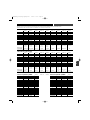
Scanplans for 1800 Series
Please make certain that you have a licence for the frequency you are intending to use BEFORE you operate the system.
The regulations differ from country to country and might change from time to time
E-Band (795.500 - 820.000 MHz)
Scan - 1 Scan - 2 Scan - 3 Scan - 4 Scan - 5 Scan - 6 Scan - 7 Scan - 8 Scan - 9
1 795,500 796,250 795,550 798,250 795,825 796,000 796,500 800,100 806,250
2 796,500 798,500 796,775 799,200 796,950 796,700 796,900 800,850 806,750
3 798,750 799,750 797,050 799,900 797,500 797,100 797,700 802,350 807,000
4 800,225 802,225 797,750 802,825 798,600 797,900 800,775 803,100 808,250
5 802,500 803,500 806,850 803,350 802,425 806,300 806,100 806,850 808,500
6 810,025 812,000 807,400 808,900 809,325 807,000 806,500 807,600 811,500
7 812,500 813,700 811,100 809,725 810,425 810,775 810,225 816,450 811,750
8 814,500 815,750 811,725 811,350 811,250 812,700 810,975 817,200 813,000
9 816,225 818,225 813,050 812,100 811,825 813,500 812,500 818,700 813,250
10 818,500 819,250 813,800 812,575 813,500 813,900 813,700 819,450 813,750
Notes (**) Fullrange 1 Fullrange 2 use for: use for: use for: use for: use for: limited to limited to
compatible with compatible with German user German user German user French series 3 French series 2 800.100 MHz - European TV-
4000/5000 4000/5000 group 4 group 3 group 2 819.900 MHz Channel 63
scan plan scan plan
Used European
TV-Channels 61, 62, 63, 64 61, 62, 63, 64 61 + 63 62 + 63 61, 62, 63 61 + 63 61, 62, 63 62, 63, 64 63
(**) These notes are valid on the 01.01.2007. Please check the latest regulations BEFORE operating the system.
F-Band (840.125 - 864.875 MHz)
Scan - 1 Scan - 2 Scan - 3 Scan - 4 Scan - 5 Scan - 6 Scan - 7 Scan - 8 Scan - 9
1 863,125 847,250 846,850 846,250 846,100 840,125 863,100 855,275 846,875
2 863,375 848,375 847,400 847,200 846,600 840,875 863,500 855,900 847,125
3 864,375 850,125 848,525 847,900 847,575 842,375 864,300 856,175 847,625
4 864,875 854,625 849,925 850,825 848,050 842,625 864,700 857,625 847,875
5 840,250 854,900 851,050 851,350 850,425 843,375 856,300 857,950 849,625
6 841,375 857,125 851,600 856,900 858,425 858,750 856,800 860,900 849,875
7 842,750 858,250 859,100 857,725 859,250 859,000 857,050 861,200 857,850
8 843,375 858,625 859,725 859,350 859,825 859,500 858,300 861,750 860,050
9 844,625 860,400 861,050 860,100 861,500 861,000 858,550 863,125 860,300
10 847,000 861,125 861,800 860,575 861,900 861,750 859,050 863,375 860,800
Notes (**) Fullrange 1 Fullrange 2 use for: use for: use for: prefered use for prefered use for UK-Shared
compatible with compatible with German user German user German user The Netherlands Spain (1-4) frequencies
4000/5000 4000/5000 group 4 group 3 group 2
scan plan scan plan
Used European deregulated(*) deregulated(*) deregulated(*)
TV-Channels 67, 68 68 + 69 68 + 69 68 + 69 68 + 69 67 + 69 + 69 + 69 68 + 69
(*) When operating in the deregulated frequencyrange (863.000 - 865.00 MHz) in countries following the R&TTE you have to set the transmitter power to LOW (10mW).
(**) These notes are valid on the 01.01.2007. Please check the latest regulations BEFORE operating the system.
C-Band (541.500 - 566.375 MHz) D-Band (655.500 - 680.375 MHz)
Scan - 1 Scan - 2 Scan - 3 Scan - 4 Scan - 5 Scan - 1 Scan - 2 Scan - 3
1 541,500 541,875 541,500 1 655,500 655,875 655,500
2 544,000 542,250 541,750 2 658,000 656,250 655,750
3 544,375 544,500 542,625 3 658,375 658,500 656,625
4 545,250 545,750 544,500 4 659,250 659,750 658,500
5 545,500 546,000 544,750 5 659,500 660,000 658,750
6 547,500 546,500 545,500 6 661,500 660,500 659,500
7 548,375 550,375 548,750 7 662,375 664,375 662,750
8 548,750 551,500 551,250 8 662,750 665,500 665,250
9 555,625 557,625 557,250 9 669,625 671,625 671,250
10 557,750 558,000 558,375 10 671,750 672,000 672,375
11 560,750 560,000 559,125 11 674,750 674,000 673,125
12 561,750 560,500 560,125 12 675,750 674,500 674,125
13 562,125 561,750 560,500 13 676,125 675,750 674,500
14 564,000 562,750 561,375 14 678,000 676,750 675,375
15 564,250 564,250 564,625 15 678,250 678,250 678,625
16 565,500 566,250 565,125 16 679,500 680,250 679,125
used European 29, 30, 31, 32 29, 30, 31, 29, 30, 31, 32 used European 44, 45, 46, 47 44, 45, 46, 47 44, 45, 46, 47
TV-Channels 32, 33 TV-Channels
*Specifications are subject to change without notice.
E
N
OM1800Ser_dual(europ).qxd:Layout 1 1/10/07 14:35 Page 15

16
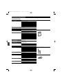
Overall System
ATW-R1820 Dual-channel Receiver
ATW-T1801 UniPak
™
Body-pack Transmitter
ATW-T1802 Plug-on Transmitter
Specifications
*
UHF Operating Frequency
Band C : 541.500 to 566.375 MHz
Band D : 655.500 to 680.375 MHz
Band E : 795.500 to 820.000 MHz
Band F : 840.125 to 864.875 MHz
Number of Operating Frequencies up to 996 frequencies per band
Frequency Stability ±0.005%, Phase Lock Loop frequency control
Modulation Mode FM
Normal Deviation ±10kHz
Operating Range 100m (300’) typical
Operating Temperature Range -5º C (23º F) to 45º C (113º F)
Frequency Response 70 Hz to 15 kHz
Receiving System Dual independent RF sections,
automatic-switching diversity
Image Rejection >50 dB typical
Signal-to-Noise Ratio 104 dB at 30 kHz deviation (A-weighted),
maximum modulation 37 kHz
Total Harmonic Distortion <1% (±10 kHz deviation at 1 kHz)
Sensitivity 25 dBµV, (S/N 60 dB at 5 kHz deviation, A-weighted)
Audio Output (balanced) 27 mV (at 1 kHz, ±5 kHz deviation)
Output Connector 3-pin mini XLR (TA3M-type)
Monitor Headphone Output (typical) 35 mW max., 32 ohm load (per channel)
Monitor Headphone Jack 3.5 mm TRS, signals on both Tip and Ring
External Power Requirements 12V DC nominal, 500 mA
Batteries (not included) Six 1.5V AA alkaline
Current Consumption (battery)
Dual-channel Operation 600 mA typical
Single-channel Operation 350 mA typical
Battery Life
Dual-channel Operation 6 hours typical*
Single-channel Operation 10 hours typical*
* depending on battery type and use pattern
Dimensions 85.0 mm (3.35”) W x 133.0 mm (5.24”) H x 36.0 mm (1.42”) D
Net Weight (without batteries) 425 grams (15.0 oz)
Accessories Included Two flexible UHF antennas; two 45cm (18”) TA3F to XLRM
output cables; belt pouch
RF Power Output High: 30 mW; Low: 10 mW, nominal
Spurious Emissions According to R&TTE Directive
Dynamic Range >105 dB, A-weighted
Input Connections High impedance, low impedance, bias
Batteries (not included) Two 1.5V AA alkaline
Current Consumption High: 180 mA; Low: 160 mA, typical
Battery Life Approximately 6 hours (High); 8 hours (Low),
depending on battery type and use pattern
Dimensions 66.0 mm (2.60”) W x 87.0 mm (3.43”) H x 24.0 mm (0.94”) D
Net Weight (without batteries) 80 grams (2.8 oz)
RF Power Output High: 30 mW; Low: 10 mW, nominal
Spurious Emissions According to R&TTE Directive
Dynamic Range >105 dB, A-weighted
Input Connector 3-pin locking XLRF-type
Microphone Power Provides power to condenser microphones rated to
operate on 12V phantom power or less.
Batteries (not included) Two 1.5V AA alkaline
Current Consumption High: 180 mA; Low: 160 mA, typical
Battery Life Approximately 6 hours (High); 8 hours (Low),
depending on battery type and use pattern
Dimensions 40.0 mm (1.57”) x 111.0 mm (4.37”) x 40.0 mm (1.57”)
Net Weight (without batteries) 199 grams (7.0 oz)
*Specifications are subject to change without notice.
E
N
OM1800Ser_dual(europ).qxd:Layout 1 1/10/07 14:35 Page 16

E
N
Disclaimer
Audio-Technica operates a policy of continuous development. Audio-Technica reserves the right
to make changes and improvements to any of the products described in this document without
prior notice.
Under no circumstances shall Audio-Technica be responsible for any loss of data or income or
any special, incidental, consequential or indirect damages howsoever caused.
The contents of this document are provided ”as is”. Except as required by applicable law, no
warranties of any kind, either express or implied, including, but not limited to, the implied
warranties of merchantability and fitness for a particular purpose, are made in relation to the
accuracy, reliability or contents of this document. Audio-Technica reserves the right to revise this
document or withdraw it at any time without prior notice.
The availability of particular products may vary by country. Please check with the distributor for
your territory. In some countries there may be restrictions in using this equipment. Please check
with your local radio frequency authorities.
Two-Years Limited Warranty
Audio-Technica microphones and accessories purchased in the UK and EU / Europe are
guaranteed for two years from date of purchase by Audio-Technica Ltd. to be free of defects in
materials and workmanship. In the event of such defect, product will be repaired promptly
without charge or, at our option, replaced with a new product of equal or superior value, if the
faulty product is delivered to Audio-Technica Ltd., prepaid, together with the proof of purchase.
Prior approval from Audio-Technica Ltd. is required for return. This warranty excludes defects
due to normal wear, abuse, shipping damage, or failure to use product in accordance with
instructions. This warranty is void in the event of unauthorized repair or modification.
For return approval and shipping information, contact the Service Department,
Audio-Technica Ltd. Tel: +44 (0)113 277 1441.
Outside the U.K, please contact your local dealer for warranty details.
Visit our Website!
www.audio-technica.com
Audio-Technica Ltd
Technica House , Royal London Industrial Estate, Old Lane, Leeds LS11 8AG England
Tel: +44 (0) 113 277 1441 - Fax: +44 (0) 113 270 4836 - Email: [email protected]
ER0040 ©2007 Audio-Technica Ltd, Printed in England.
OM1800Ser_dual(europ).qxd:Layout 1 1/10/07 14:35 Page 17

wireless
wireless
wireless
wireless
wireless
Séries 1800
Systèmes Microphone UHF (deux canaux)
Pour montage sur camescope
AT W - R
1820
Récepteur deux canaux
AT W -T
1801
Émetteur ceinture UniPak™
AT W -T
1802
Émetteur « Plug-on »
Installation et Utilisation
FR
!
0470
OM1800Ser_dual(europ).qxd:Layout 1 1/10/07 14:35 Page 19

Cet appareil est conforme à la directive européenne R&TTE 1999/05/EC.
Son utilisation est soumise à la réserve de ne pas provoquer d’interférences nuisibles.
À l’attention
des porteurs de stimulateurs cardiaques ou défibrillateurs :
Toute source d’énergie HF (fréquences radio) est susceptible d’interférer avec le fonctionnement normal de l’appareil implanté. Tous les microphones
HF sont dotés d’émetteurs de faible puissance (sortie inférieure à 0,05 W) : il est donc peu probable qu’ils constituent un problème, d’autant plus
qu’ils sont tenus à quelques dizaines de centimètres de la région cardiaque. En revanche, un émetteur portable, lui, se tient à proximité immédiate
du corps. Nous suggérons donc de l’attacher à la ceinture, et non de le dissimuler dans une poche poitrine par exemple, où il se trouverait à
proximité immédiate de l’appareil médical. Veuillez également noter que tout éventuel problème de fonctionnement de l’appareil médical cessera
en éteignant la source de puissance HF. Si vous avez des questions ou si vous rencontrez des problèmes lors de l’utilisation d’appareils HF, veuillez
contacter votre spécialiste ou votre fournisseur de matériel médical.
ATTENTION ! Les circuits électroniques se trouvant à l’intérieur du récepteur et de l’émetteur ont été réglés avec précision pour des performances
optimales, en conformité avec les réglementations nationales. N’essayez pas d’ouvrir le récepteur ou l’émetteur : vous annuleriez la garantie, et vous
risquez de provoquer des dysfonctionnements.
Avertissement : Pour éviter tout incendie ou électrocution, n’exposez pas cet appareil à la pluie ni à l’humidité.
À propos des interférences HF
N’oubliez pas que les fréquences utilisées pour les liaisons audio HF sont partagées avec d’autres services radio.
Assurez-vous par conséquent que vous respectez les réglementations en vigueur, au niveau national, dans le pays où vous désirez utiliser le système.
Si vous désirez être assisté dans le choix des fréquences de travail ou pour la mise en place de votre système, veuillez contacter votre revendeur local
ou, directement, Audio-Technica. Vous trouverez également des informations sur la HF sur notre site Web, www.audio-technica.com.
Table des matières
Configurations système 21
Fonctions des systèmes Series 1800 (deux canaux) 22
Présentation rapide du fonctionnement du système 23
Les commandes du récepteur deux canaux ATW-R1820 24
Fonctionnement du récepteur 26
Commandes des émetteurs 29
Fonctionnement des émetteurs 30
Astuces pour obtenir de meilleurs résultats 32
Accessoires disponibles 32
Plans de Scan (recherche automatique de fréquence) pour les appareils 1800-Series 33
Caractéristiques 34
Garantie 35
20
F
R
OM1800Ser_dual(europ).qxd:Layout 1 1/10/07 14:35 Page 20

F
R
21
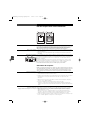
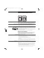
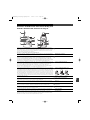
1800 Series (deux canaux)
Récepteur et composants/accessoires fournis
ATW-R1820
Récepteur deux canaux
Deux antennes
détachables
Deux câbles de sortie 45 cm,
TA3F vers XLR mâle
Housse avec pince ceinture
(pour le récepteur)
Émetteurs
AT W -T 1 8 0 1
Émetteur de poche UniPak™
ATW-T1802
Émetteur « Plug-on »
Note : Toutes les références de modèles possèdent une lettre à la fin indiquant leur bande de fréquence.
OM1800Ser_dual(europ).qxd:Layout 1 1/10/07 14:36 Page 21
La pagina si sta caricando...
La pagina si sta caricando...
La pagina si sta caricando...
La pagina si sta caricando...
La pagina si sta caricando...
La pagina si sta caricando...
La pagina si sta caricando...
La pagina si sta caricando...
La pagina si sta caricando...
La pagina si sta caricando...
La pagina si sta caricando...
La pagina si sta caricando...
La pagina si sta caricando...
La pagina si sta caricando...
La pagina si sta caricando...
La pagina si sta caricando...
La pagina si sta caricando...
La pagina si sta caricando...
La pagina si sta caricando...
La pagina si sta caricando...
La pagina si sta caricando...
La pagina si sta caricando...
La pagina si sta caricando...
La pagina si sta caricando...
La pagina si sta caricando...
La pagina si sta caricando...
La pagina si sta caricando...
La pagina si sta caricando...
La pagina si sta caricando...
La pagina si sta caricando...
La pagina si sta caricando...
La pagina si sta caricando...
La pagina si sta caricando...
La pagina si sta caricando...
La pagina si sta caricando...
La pagina si sta caricando...
La pagina si sta caricando...
La pagina si sta caricando...
La pagina si sta caricando...
La pagina si sta caricando...
La pagina si sta caricando...
La pagina si sta caricando...
La pagina si sta caricando...
La pagina si sta caricando...
La pagina si sta caricando...
La pagina si sta caricando...
La pagina si sta caricando...
La pagina si sta caricando...
La pagina si sta caricando...
La pagina si sta caricando...
La pagina si sta caricando...
La pagina si sta caricando...
La pagina si sta caricando...
La pagina si sta caricando...
La pagina si sta caricando...
La pagina si sta caricando...
La pagina si sta caricando...
La pagina si sta caricando...
La pagina si sta caricando...
La pagina si sta caricando...
La pagina si sta caricando...
La pagina si sta caricando...
La pagina si sta caricando...
La pagina si sta caricando...
La pagina si sta caricando...
La pagina si sta caricando...
La pagina si sta caricando...
La pagina si sta caricando...
La pagina si sta caricando...
La pagina si sta caricando...
La pagina si sta caricando...
La pagina si sta caricando...
La pagina si sta caricando...
La pagina si sta caricando...
La pagina si sta caricando...
La pagina si sta caricando...
La pagina si sta caricando...
La pagina si sta caricando...
La pagina si sta caricando...
La pagina si sta caricando...
La pagina si sta caricando...
La pagina si sta caricando...
La pagina si sta caricando...
La pagina si sta caricando...
La pagina si sta caricando...
La pagina si sta caricando...
La pagina si sta caricando...
La pagina si sta caricando...
La pagina si sta caricando...
La pagina si sta caricando...
La pagina si sta caricando...
La pagina si sta caricando...
La pagina si sta caricando...
La pagina si sta caricando...
La pagina si sta caricando...
La pagina si sta caricando...
La pagina si sta caricando...
La pagina si sta caricando...
La pagina si sta caricando...
La pagina si sta caricando...
La pagina si sta caricando...
La pagina si sta caricando...
-
 1
1
-
 2
2
-
 3
3
-
 4
4
-
 5
5
-
 6
6
-
 7
7
-
 8
8
-
 9
9
-
 10
10
-
 11
11
-
 12
12
-
 13
13
-
 14
14
-
 15
15
-
 16
16
-
 17
17
-
 18
18
-
 19
19
-
 20
20
-
 21
21
-
 22
22
-
 23
23
-
 24
24
-
 25
25
-
 26
26
-
 27
27
-
 28
28
-
 29
29
-
 30
30
-
 31
31
-
 32
32
-
 33
33
-
 34
34
-
 35
35
-
 36
36
-
 37
37
-
 38
38
-
 39
39
-
 40
40
-
 41
41
-
 42
42
-
 43
43
-
 44
44
-
 45
45
-
 46
46
-
 47
47
-
 48
48
-
 49
49
-
 50
50
-
 51
51
-
 52
52
-
 53
53
-
 54
54
-
 55
55
-
 56
56
-
 57
57
-
 58
58
-
 59
59
-
 60
60
-
 61
61
-
 62
62
-
 63
63
-
 64
64
-
 65
65
-
 66
66
-
 67
67
-
 68
68
-
 69
69
-
 70
70
-
 71
71
-
 72
72
-
 73
73
-
 74
74
-
 75
75
-
 76
76
-
 77
77
-
 78
78
-
 79
79
-
 80
80
-
 81
81
-
 82
82
-
 83
83
-
 84
84
-
 85
85
-
 86
86
-
 87
87
-
 88
88
-
 89
89
-
 90
90
-
 91
91
-
 92
92
-
 93
93
-
 94
94
-
 95
95
-
 96
96
-
 97
97
-
 98
98
-
 99
99
-
 100
100
-
 101
101
-
 102
102
-
 103
103
-
 104
104
-
 105
105
-
 106
106
-
 107
107
-
 108
108
-
 109
109
-
 110
110
-
 111
111
-
 112
112
-
 113
113
-
 114
114
-
 115
115
-
 116
116
-
 117
117
-
 118
118
-
 119
119
-
 120
120
-
 121
121
-
 122
122


Audio-Technica ATW-R1820 Manuale utente
- Tipo
- Manuale utente
- Questo manuale è adatto anche per
in altre lingue
- français: Audio-Technica ATW-R1820 Manuel utilisateur
- español: Audio-Technica ATW-R1820 Manual de usuario
- Deutsch: Audio-Technica ATW-R1820 Benutzerhandbuch
- Nederlands: Audio-Technica ATW-R1820 Handleiding
- português: Audio-Technica ATW-R1820 Manual do usuário
Documenti correlati
Altri documenti
-
 Alto Professional STEALTHMK2XUS Guida utente
-
Alto Professional Stealth Wireless MKII Guida utente
-
-
WisyCom MRK 950 EX Manuale utente
-
-
Audio Technica AT-ONE Istruzioni per l'uso
-
-
-
-
Hitec RCD IFHHFM-4-72 Manuale utente
