Lince 9553-GOLD-BOBBY-AM-E Istruzioni per l'uso
- Categoria
- Illuminazione di comodità
- Tipo
- Istruzioni per l'uso
Questo manuale è adatto anche per

IT
EN
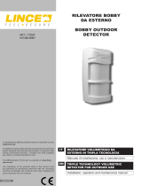
BOBBY RADIO 869 MHz SERIE GOLD
Manuale di installazione, uso e manutenzione
Installation, operation and maintenance manual
BOBBY WIRELESS 869 MHz GOLD
SERIES
ART. / ITEM:
9502-GOLD-BOBBY
9553-GOLD-BOBBY-AM/E
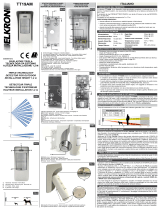
BOBBY GOLD
MADE IN ITALY
La dichiarazione CE del presente articolo è reperibile sul sito www.
lince.net.
L’installazione dei prodotti riportati nel presente manuale deve
essere eseguita da personale specializzato in possesso delle dovute
conoscenze tecniche; i prodotti sono stati progettati per utilizzo in
contesti domestici e civili.
The CE declaration of this item is available on www.lince.net
website.
The installation of the products listed in this manual must be
performed by specialized personnel with the necessary technical
knowledge; the products have been designed for use in domestic
and civil contexts.

LINCE ITALIA
2
- Istruzioni originali -
1. INTRODUZIONE ................................................................................................ 2
1.1 CARATTERISTICHE GENERALI ........................................................... 2
1.2 CARATTERISTICHE TECNICHE ...........................................................3
1.3 CONTENUTO DELLA CONFEZIONE .................................................... 3
1.4 IDENTIFICAZIONE DELLE PARTI ......................................................... 4
1.4.1 Cover PIR superiore ....................................................................4
2. FUNZIONI SPECIALI ........................................................................................ 5
2.1 FUNZIONE WIN ..................................................................................... 5
2.2 GESTIONE BATTERIA SUPPLEMENTARE .......................................... 5
2.3 FUNZIONE DES - DETECTION EVENT STORED ................................ 5
2.4 FUNZIONE SLEEP .................................................................................5
2.5 ANTIMASCHERAMENTO ...................................................................... 5
3. INSTALLAZIONE............................................................................................... 6
3.1 AVVERTENZE GENERALI .....................................................................6
3.2 VERIFICA PORTATA .............................................................................. 6
3.3 MONTAGGIO DEL RILEVATORE ..........................................................6
3.3.1 Installazione sul muro ..................................................................7
3.3.2 Installazione sul palo ................................................................... 7
3.3.3 Regolazione della distanza di rilevazione ................................... 9
3.4 GRAFICO DI COPERTURA ................................................................. 11
4. MEMORIZZAZIONE ........................................................................................ 11
5. ESEMPIO DI RILEVAMENTO ......................................................................... 12
6. ACCESSORI DISPONIBILI ............................................................................. 13
6.1 STAFFA ................................................................................................ 13
6.2 COVER PARAPIOGGIA .......................................................................13
6.3 KIT RISCALDATORE ...........................................................................13
7. RICERCA DEI GUASTI E/O MALFUNZIONAMENTI .................................... 14
8. MANUTENZIONE E VERIFICHE PERIODICHE ............................................. 15
9. SMALTIMENTO E ROTTAMAZIONE .............................................................. 15
9.1 SMALTIMENTO IMBALLAGGIO ..........................................................15
9.2 SMALTIMENTO PRODOTTO E ROTTAMAZIONE ..............................15
INDICE
Le informazioni riportate in questo manuale sono state compilate con cura, tuttavia
LINCE ITALIA S.r.l. non può essere ritenuta responsabile per eventuali errori e/o
omissioni. LINCE ITALIA S.r.l. si riserva il diritto di apportare in ogni momento e
senza preavviso, miglioramenti e/o modiche ai prodotti descritti nel presente
manuale. Consultare il sito www.lince.net per le condizioni di assistenza e garanzia.
LINCE ITALIA S.r.l. pone particolare attenzione al rispetto dell’ambiente. Tutti i
prodotti ed i processi produttivi sono progettati con criteri di eco-compatibilità.
Il presente articolo è stato prodotto in Italia.
• L’aziendahaunsistemadigestionedellaqualitàcerticatosecondola
norma ISO 9001:2015 (n° 4796 - A)
• L’aziendahaunsistemadigestioneambientalecerticatosecondola
norma ISO 14001:2015 (n° 4796 - E)
• L’azienda ha un sistema di gestione della salute e sicurezza sul lavoro
certicatosecondolanorma45001:2018(n°4796-I)
The information in this manual has been issued with care, but LINCE ITALIA S.r.l.
will not be responsible for any errors or omissions. LINCE ITALIA S.r.l. reserves the
right to improve or modify the products described in this manual at any time and
without advance notice.Terms and conditions regarding assistance and the product
warranty can be found at Lince Italia’s website www.lince.net. LINCE ITALIA
S.r.l. makes it a priority to respect the environment. All products and production
processes are designed to be eco-friendly and sustainable.
This product has been Made in Italy.
• Thecompanyhasacertiedsystemofqualitymanagementaccording
to ISO 9001:2015 (n° 4796 - A) standard.
• The company has a certied system of environmental management
according to ISO 14001:2015 (n° 4796 - E) standard.
• The company has a certied system of health and work security
managementaccordingto45001:2018(n°4796-I)standard.
-Translationoftheoriginalinstructions(originalinstructionsinItalian)-
1. INTRODUCTION ............................................................................................... 2
1.1 GENERAL FEATURES .......................................................................... 2
1.2 TECHNICAL FEATURES ....................................................................... 3
1.3 PACKAGING CONTENTS ..................................................................... 3
1.4 PARTS IDENTIFICATION.......................................................................4
1.4.1 Upper PIR cover ..........................................................................4
2. SPECIAL FUNCTION ........................................................................................ 5
2.1 WIN FUNCTION .....................................................................................5
2.2 ADDITIONAL BATTERY MANAGE ........................................................5
2.3 DES FUNCTION - DETECTION EVENT STORED ................................ 5
2.4 SLEEP FUNCTION ................................................................................5
2.5 ANTI-MASKING......................................................................................5
2. INSTALLATION ................................................................................................. 6
3.1 GENERAL PRECAUTIONS ................................................................... 6
3.2 RADIO RANGE CHECK .........................................................................6
3.3 MOUNTING THE DETECTOR ............................................................... 6
3.3.1 Wall mounting .............................................................................. 7
3.3.2 Pole mounting .............................................................................7
3.3.3 Detection range adjustment ........................................................ 9
3.4 COVERED AREA PATTERN ................................................................ 11
4. STORAGE ....................................................................................................... 11
5. DETECTING EXAMPLE .................................................................................. 12
6. AVAILABLE ACCESSORIES .......................................................................... 13
6.1 BRACKET .............................................................................................13
6.2 RAIN COVER ....................................................................................... 13
6.3 HEATER KIT .........................................................................................13
7. TROUBLE SHOOTING ................................................................................... 14
8. MAINTENANCE AND PERIODIC CHECKS ................................................... 15
9. DISPOSAL AND SCRAPPING ........................................................................ 15
CONTENTS
1. INTRODUZIONE
Il rilevatore da esterno BOBBY GOLD è composto da due sensori
passivi dual PIR e da una microonda a 24 GHz. L’elettronica
è stata progettata per garantire le massime prestazioni in
ambiente esterno e a temperature rigide. I fasci sono orientabili
e permettono di ottenere una copertura orizzontale distribuita su
170°. Oltre alle funzioni di rilevazione il rilevatore è dotato della
funzione di ANTIMASKING ad infrarossi attivi. Tale funzione
è stata implementata per rendere il rilevatore inattaccabile da
quanti potrebbero avere accesso al sito dove il rilevatore è
installato durante il periodo in cui il sistema risulta disinserito;
segnala ogni tentativo di impedire il suo funzionamento bloccando
(mascherando) il suo campo di rilevazione che avviene tramite
2 PIR ed una Microonda a 24 GHz. L’ altezza di installazione
è compresa tra 1 e 1,2 m con area di una copertura di 15 m
(12 m nella versione con mw) ed apertura di 85°. Impostazioni
eseguibili direttamente dalla centrale quali settaggi AND/OR
(triplo AND, doppio OR, l’esclusione della microonda ecc.),
sensibilità di PIR, portata della Microonda e della rilevazione al
mascheramento. La regolazione micrometrica del PIR inferiore
permette di adattare la portata di rilevazione da 3 a 15 m.
Realizzato completamente in policarbonato resistente ad urti e
raggi UV con lente di Fresnel made in USA e ltri solari made in
Japan. I 4 LED di segnalazione di cui 2 verdi per i PIR, 1 giallo
per la microonda ed 1 rosso per l’allarme permettono di sapere
se una tecnologia sta rilevando o meno.
1. INTRODUCTION
The outdoor detector BOBBY GOLD consists of two dual PIR
passive sensors and a 24 GHz microwave. The electronics
are designed to provide maximum performance in outdoor and
extreme conditions. The beams are adjustable and allow for a
horizontal coverage of 170°. In addition to the detection functions,
the detector is equipped with the active infrared ANTIMASKING
function.
This function has been implemented to make the detector
unassailable from anyone who may have access to the site
where the detector is installed during the period when the system
is turned off; Indicates any attempt to prevent its operation by
blocking (masking) its detection range by means of 2 PIRs and
a 24 GHz Microwave. The installation height is between 1 and
1.2 m with area of 15 m coverage and opening of 85°. Settings
executable directly from the control panel such as AND / OR (triple
AND, double OR, microwave exclusion etc.), PIR sensitivity,
Microwave ow, and mask detection. The microprocessor control
of the lower PIR allows to adjust the detection range from 3 to 15
m. Made entirely of impact resistant polycarbonate and UV rays
with Fresnel lens made in USA and solar lters made in Japan.
The 4 LEDs of which 2 green for the PIRs, 1 yellow for the
microwave and 1 for the alarm signal allow you to know whether
a technology is detecting or not.

3
LINCE ITALIA
1.2 CARATTERISTICHE TECNICHE
9502-GOLD-BOBBY-AM 9553-GOLD-BOBBY-AM-E
Alimentazione / Power supply Batteria al litio AA 3,6 V / Lithium battery AA 3,6 V (Lince pn: 001515/00198AB)
Consumo / Current consumption 35 µA stand-by
Frequenza microonda / Microwavefrequncy Banda K / K Band NO
Frequenza di trasmissione / Transmissionfrequency 869,40 MHz-869,65 MHz 1 canale / 1 channel
868,00 MHz-868,60 MHz 4 canali / 4 channels
FH Frequency Hopping
TDMA Time Division Multiple Access
AES Advanced Encryption Standard
Portata / Wireless range no a 1500 m in aria libera / up to 1500 m in free air
Funzione antimanomissione /Antitamperfunction Microswitch
Antimascheramento / Antimasking IR attivi / Active IR
Funzione WIN / WINfunction SI / YES NO
Batteria supplementare (non fornita) / Additional battery (not supplied) SI / YES NO
Portata di rilevazione / Detection range 3 m ÷ 12 m 3 m ÷ 15 m
Ampiezza orizzontale del fascio / Horizontal beam detection 85°
Escursione orizzontale / Horizontal detection excursion ±45°.
LED di segnalazione /Signal LEDs 4 3
Grado di protezione contenitore / Enclosuredegreeofprotection IP 44
Classe ambientale / Environmentalclassication Classe IV (EN 50131-4) / Class IV (EN 50131-4)
Grado di sicurezza / Security grading Grado 2 (EN 50131-2-4)
Grade 2 (EN 50131-2-4)
Grado 2 (EN 50131-2-2)
Grade 2 (EN 50131-2-2)
Contenitore / Casing Policarbonato resistente UV / UV resistant polycarbonate
Temperatura di esercizio / Operating temperature -25 °C ÷ +60 °C
Dimensioni esterne (LxPxA mm) /
External dimensions
(WxDxH mm) 81x76x189
Peso (g) / Weight (g) 400 (compreso staffe) / 400 (including brackets)
1.2 TECHNICAL FEATURES
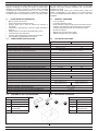
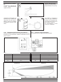
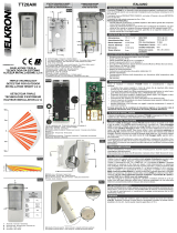
1.3 CONTENUTO DELLA CONFEZIONE
C
A
B D
1.3 PACKAGING CONTENTS
Tabella 1
Part. Identicazione
ARilevatore
BStaffa
CKit di ssaggio al muro
e cavo WIN
DIstruzioni
Table 1
Ref. Identication
ADetector.
BBracket
CKit for wall mounting
and WIN cable
DIstructions
Fig. 1
1.1 CARATTERISTICHE GENERALI
• Basso consumo di corrente.
• Circuito di rilevazione batteria scarica.
• Sensore DUAL PIR a lente di Fresnel più sensore a
microonda.
• Contenitore in policarbonato e lenti di Fresnel resistenti ai
raggi UV.
• Design estetico e meccanico particolarmente curato.
• Conforme alle norme EN 50131.
• Funzione WIN: alimentazione tramite rete principale.
• Pacco batteria supplementare (non fornito);
1.1 GENERAL FEATURES
• Low consumption.
• Low battery detecting circuit.
• DUAL PIR sensor with Fresnel lens and microwave sensor.
• Casing in polycarbonate and Fresnel lenses UV resistant.
• Carefully developed aesthetic and mechanical design .
• EN 50131compliant.
• WIN function: power from the mains;
• Additional battery pack (not supplied)
La funzione Pet immunity è disponibile se utilizzato in triplo AND.
Supporto di ssaggio in acciaio inox (fornito) e staffe da palo
disponibili su richiesta. Provvisto di sistema WIN (possibilità
di alimentazione supplementare esterna a 12 V che lo rende
equiparabile ad un rilevatore lare) è alimentato normalmente
con batteria al litio non ricaricabile 2/3 A 3,6V 1.700 mAh (fornita).
The Pet immunity function is available if used in Triple AND.
Stainless steel xing bracket (supplied) and pole brackets
available on request.
Provided with WIN system (12V external power supply that
makes it comparable to a spin detector) is normally powered
by a non-rechargeable lithium battery 2/3 A 3.6V 1.700 mAh
(supplied).

LINCE ITALIA
4
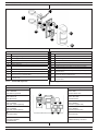
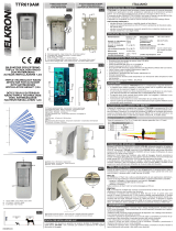
Fig. 2
1.4 IDENTIFICAZIONE DELLE PARTI 1.4 PARTS IDENTIFICATION
Tabella 1
Part. Identicazione
AViti di ssaggio del supporto rilevatore sulla staffa.
BVite di ssaggio del coperchio con lente.
CCoperchio con lente di Fresnel.
DPomello con vite metrica di regolazione PIR basso.
ESupporto elettronica.
FMicrointerruttore con funzione antistrappo (solo se ssato con la vite
A).
GStaffa in acciaio inox.
HStaffe per ssaggio a palo (non fornite art.: 001805/00102AA).
IVite metrica M4 x 6 inox per ssaggio staffe ad “U” (q.tà 4) contenute
nel kit accessorio art. 001805/00102AA.
LViti metriche M4 x 10 inox (q.tà 4) contenute nel kit accessorio art.
001805/00102AA.
L
A
D
G
I
H
E
F
I
L
C
B
Table 1
Ref. Identication
ABracket screws.
BCover mounting screw.
CCover with Fresnel lens.
DAdjusting knob for lower PIR (PIR2).
EElectronic holder.
FAnti Tamper function micro switch (only if A screw is mounted).
GStainless steel support.
HStainless steel pole mounting brackets (not supplied item:
001805/00102AA).
IStainless Steel metric screw M4 x 6 for “U” brackets xing (4 pcs )
enclosed into kit item 001805/00102AA.
LStainless Steel metric screw M4 x 10 (4 pcs) enclosed into kit item
001805/00102AA.
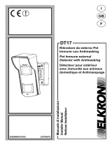
1.4.1 Cover PIR superiore
Tabella 2 / Table 2
Descrizione Description
A
LED 1 ROSSO
LED allarme generale
A
LED 1 RED
General alarm LED
B
LED 2 GIALLO
LED Microonda
B
LED 2 YELLOW
LED Microwave
C
LED 3 VERDE
LED PIR 1 (PIR superiore)
C
LED 3 GREEN
LED PIR 1 (upper PIR)
D
LED 4 VERDE
LED PIR 2 (PIR inferiore)
D
LED 4 GREEN
LED PIR 2 (lower PIR)
E
Connettore WIN
E
WIN connector
F
Connettore batteria
supplementare
F
Additional battery connector
1.4.1 Upper PIR cover
D B
A C
F
E
Fig. 3

5
LINCE ITALIA
2. FUNZIONI SPECIALI 2. SPECIAL FUNCTION
2.1 FUNZIONE WIN
Utilizzando la funzione WIN (Wired Interface Network) è possibi-
le alimentare il dispositivo attraverso l’alimentazione principale,
mantenendo la Microonda sempre accesa ed avendo dunque
le stesse prestazioni di un rilevatore lare. Quando il rilevatore
è alimentato con una tensione maggiore di 9 V, viene automati-
camente attivata la funzione WIN. In modalità WIN i LED sono
sempre attivi e la microonda sempre accesa. Quando la tensio-
ne di alimentazione del rilevatore scende sotto 8 V, il rilevatore
ritorna in funzionamento in modalità batteria, dove i LED sono
spenti e la microonda subordinata all’accensione di uno dei PIR.
Il cavo per connettere la scheda all’alimentazione WIN è fornito
in dotazione, collegandolo prestando la massima attenzione al
verso del connettore.
2.1 WIN FUNCTION
Using the WIN function (Wired Interface Network) it is possible
to power the devices from the mains, keeping the Microwave on
and therefore offering the same performance as a wired detector.
When the detector is powered at a voltage higher than 9 V, the
WIN function automatically comes on. In WIN mode both LEDs
and microwave are always on. When the detector feed voltage
drops below 8 V, the detector goes back to battery-operation
mode, where the LEDs are off and the microwave is subordinate
to the activation of one of the PIRs.
The cable to connect the board to the WIN power supply is sup-
plied, connecting it by paying attention to the connector side.
2.3 FUNZIONE DES - DETECTION EVENT STORED
Nel caso in cui la periferica rilevasse un evento di allarme in un
periodo in cui non comunica con la centrale (per esempio se
l'ambiente è disturbato) il dato di allarme verrà tenuto in attesa
e comunicato alla centrale non appena la comunicazione viene
ristabilita. La centrale, se il sistema è ancora allarmato, gestirà
l’allarme DES come un allarme normale (uscita sirena, SMS etc).
In memoria eventi saranno distinguibili gli allarmi normali e gli
allarmi DES.
2.3 DES FUNCTION - DETECTION EVENT STORED
If the device detects an alarm event at a time when it does
not communicate with the control panel (for example, if the
environment is disturbed), the alarm data will be kept on hold and
communicated to the control panel as soon as communication is
restored. The control panel, if the system is still alarmed, will
handle the DES alarm as a normal alarm (siren output, SMS
etc). In event memory, normal alarms and DES alarms can be
distinguished.
NOTA
La funzione DES è disponibile sulla centrale a partire dalla re-
visone 2.x.
NOTE
The DES function is available on the control panel from the 2.x
revision.
2.4 FUNZIONE SLEEP
Questa funzione pone la periferica in uno stato dormiente a
basso consumo (in cui non trasmette e non rileva); nel caso
debba essere rimossa la centrale per eventuale manutenzione.
La periferica una volta entrata in questa modalità dopo un'ora
si riattiva per un minuto, controllando la presenza della trama
della centrale e, qualora non sia presente, rientra in uno stato
dormiente no all'ora successiva.
2.4 SLEEP FUNCTION
This function puts the device in a sleepy low-power state (where
not transmitting and can not detect); in case the control panel
must to be removed for maintenance. The device once you enter
this mode after an hour wakes for a minute by controlling the
presence of the message of the control panel and, if not present,
fall again into a sleepy state until the next hour.
2.2 GESTIONE BATTERIA SUPPLEMENTARE
Per il collegamento di una batteria supplementare da 3,6V
LiSOCl2 o LiMnO2 è possibile acquistare il kit 001805/00152AB.
2.2 ADDITIONAL BATTERY MANAGE
To connect an additional 3.6 V LiSOCl2 or LiMnO2 battery it is
possible to buy the kit 001805/00152AB.
2.5 ANTIMASCHERAMENTO
Il rilevatore 9502-GOLD-BOBBY e 9553-GOLD-BOBBY-AM/E
sono dotati di antimascheramento a infrarossi attivi per la prote-
zione dei sensori piroelettrici, che genera un segnale di mano-
missione entro 3,5 minuti. Per abilitare il funzionamento corretto
della rilevazione di mascheramento (Anti-masking), è necessa-
rio consentire al rilevatore di studiare ed analizzare automatica-
mente le condizioni ambientali dell’area che deve proteggere.
Questa procedura è obbligatoria per assicurare la corretta se-
gnalazione della condizione di mascheramento. La procedura da
seguire è la seguente:
• Dopo aver memorizzato correttamente il rilevatore, chiudere
il coperchio ed effettuare tutte le prove di portata necessarie
per il funzionamento desiderato.
• Tenersi fuori dall’area di copertura del rilevatore per circa
4 minuti afnché, durante questo periodo, non venga
rilevatanessuna presenza e vericare che non vi siano
oggetti nel raggio di 1 m.
2.5 ANTI-MASKING
The detector 9502-GOLD-BOBBY and 9553-GOLD-BOBBY-
AM/E are equipped with an active IR anti-masking function to
protect the pyroelectric sensors. It emits a tampering signal
within 3 minutes.
To enable the correct operation of the masking detection system
(Anti-masking), allow the detector to study and analyse the envi-
ronmental conditions of the area to be protected. This procedu-
re is mandatory to ensure the correct signalling of the masking
condition.
Follow the procedure below:
• Once correctly stored the detector, close the lid and run all
the ow tests required;
• Keep out of reach of detector for about 4 minutes in order
thatnot detected any presence and pay attention that there
are noobjects within 1 m.

LINCE ITALIA
6
3.3 MONTAGGIO DEL RILEVATORE
L’altezza di installazione deve essere compresa tra i 1 m min. ed
1,2 m max (terreno non in pendenza).
Se nell’area di copertura c’è la possibilità che vi sia presenza di
animali di medie dimensioni si consiglia di installare il rilevatore
ad una altezza tale da evitare che il fascio superiore rilevi la
presenza dell’animale stesso (v. g.19, 20, 21).
Fissare la staffa di ancoraggio a muro, o su palo, stabile ed
immune da oscillazioni.
• Fissare il supporto rilevatore ad innesto sulla staffa ed avvitare
le due viti A.
• Applicare la copertura frontale ssandola con la vite B (g. 2)
3.2 VERIFICA PORTATA
Prima di installare il dispositivo è consigliabile vericare la
bontà del segnale visualizzandone l'intensità direttamente
sulla centrale. Disturbi e condizioni ambientali infatti possono
alterarne la qualità; è consigliato dunque effettuare il test ad
una distanza superiore rispetto a quella effettiva di installazione
e interponenendo tutti gli ostacoli che potrebbero presentarsi
durante il normale utilizzo (es.: chiudere porte, nestre, etc...).
3.2 RADIO RANGE CHECK
Before installing the device it is advisable to verify the quality
by displaying the intensity signal directly on the control panel
Noise and environmental conditions may alter its quality; is
recommended, therefore, carry out the test at a distance greater
than the actual installation and interposing all obstacles that may
arise during normal use (eg .: close doors, windows, etc...).
• Apporre sempre il coperchio con lente di Fresnel prima di
effettuare le prove di copertura, senza lente il rilevatore non
funziona.
È buona norma, prima di installare il rilevatore BOBBY fare una
attenta valutazione dell’area da proteggere, evitando siti dove
possano esserci piante a ridosso del rilevatore e/o piante che
crescendo possano arrivare all’altezza del rilevatore stesso
creando così fastidiosi falsi allarmi. La conformazione del terreno
è un altro elemento importante; se nell’area da proteggere sono
presenti dossi, animali anche relativamente piccoli, potrebbero
essere rilevati da entrambi i fasci IR con conseguente generazione
di falso allarme. L’altezza di ssaggio del rilevatore è un fattore
fondamentale per il corretto funzionamento, se si installa ad
una altezza inferiore al metro è possibile che animali di media
taglia possano essere rilevati, altresì se si esagera nell’altezza
di ssaggio (oltre 1,2 m) si avrà una zona non protetta inferiore
troppo marcata a discapito quindi della sicurezza.
3. INSTALLAZIONE
3.1 AVVERTENZE GENERALI
Prima dell'installazione vericare le seguenti condizioni:
• la parete non deve presentare avvallamenti o sporgenze
eccessive;
• installare il rilevatore su superci rigide prive di vibrazioni;
• evitare il posizionamento del rilevatore vicino a fonti di
calore o alla luce diretta del sole;
• evitare la riessione dell’energia elettromagnetica su ampie
superci quali, ad esempio, specchi, pareti metalliche, etc.;
• evitare di puntare il rilevatore su lampade uorescenti o
comunque di porlo nelle immediate vicinanze delle stesse.
• per i collegamenti è consigliabile utilizzare un cavo
schermato e, preferibilmente, un cavo per ogni rilevatore.
• separare i cavi dell’impianto di allarme da quelli della rete
elettrica.
Il rilevatore può essere installato in ambiente esterno (secondo
quanto prescritto dalla normativa EN 50131-1 in classe
ambientale IV).
• Evitare di puntare il rilevatore verso oggetti in movimento o,
se ciò risultasse inevitabile, prestare la massima cura nelle
regolazioni al ne di evitare falsi allarmi.
3.3 MOUNTING THE DETECTOR
Installation height must be between 1 m and 1.20 m (not tilted
ground).
If medium-sized animals might enter the coverage area, we
recommend installing the detector at a height that allows you to
prevent the upper beam from detecting their presence (see g.
19, 20, 21).
Fix the support on a wall or on a stable pole.
• Fix the detector support and screw it with the screws A.
• Hook up and mount the front cover xing it with screw B
(g. 2).
• Be sure to install the cover with Fresnel lens before the
detector testing. Without cover, the detector doesn’t work.
Before installing BOBBY detector, it is very important to carefully
evaluate the area to be protected.
To avoid false alarms, do not install the detector behind big
trees/bushes. Also pay particular attention to the ground
conformation; if in the area to be protected there are bumps or
small animals, they could be detected by both IR beams resulting
in the generation of false alarm.
The detector installation height is a fundamental factor for the
correct working. If the installation height is lower than 1 m, small
animals could be detected; if the installation height is greater
than 1.2 m, there will be a great unprotected area in the down
portion of the detection area.
3. INSTALLATION
3.1 GENERAL PRECAUTIONS
Before starting the installation, make sure that:
• the wall does not have any pronounced depressions or
protrusions;
• install the detector on rigid surfaces, free of vibrations;
• avoid to x the detectors near to heat sources or at direct
sunlight;
• avoid electromagnetic energy reection on wide surfaces
such as mirrors, metal walls, etc.;
• avoid to x the detector in front of uorescent lamps or in
proximity of them.
• connections shielded cable is suggested and one cable per
detector is preferred.
• separate the alarm system cables from the mains cables.
The detector can be installed outdoors (according to the Class IV
EN 50131-1).
• Avoid to direct the detector towards moving objects or, if
impossible, please take care in adjusting the detector in
order to avoid false alarms.

7
LINCE ITALIA
Fig. 5
Fig. 6
Fig. 4
Fig. 7
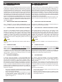
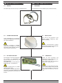
3.3.1 Installazione sul muro
• Effettuare 4 fori nel muro ed inserire
i tasselli;
• ssare ora la staffa al muro;
• Inserire il rilevatore sulla staffa e
ssarne la base con le opportune viti.
Nel ssare la staffa al muro fare attenzione
alla perpendicolarità rispetto al terreno.
3.3.2 Installazione sul palo
Nel caso di ssaggio su palo procedere
come illustrato in gura ssando la staffa
metallica principale alle due staffe da palo
(opzionali). Successivamente inserire il
rilevatore sulla staffa e ssarne la base
con le opportune viti.
Attenzione: la massima distanza
di copertura si ottiene solamente
installando il rilevatore ad un altezza di
120 cm.
NOTE:
• Evitare di puntare il rilevatore
verso oggetti in movimento o, se
ciò risulta inevitabile, prestare la
massima cura nelle regolazioni al
nedievitarefalsiallarmi;
• Montare sempre il coperchio con
lente di Fresnel prima di effettuare
le prove di copertura, senza lente
il rilevatore non può funzionare
correttamente;
• EvitareditoccareiltrisopraiPIR.
Poggiare il corpo del rilevatore sulla staffa
e farlo scendere no in fondo per far
coincidere i fori di ssaggio del corpo con
quelli della staffa. Dopo aver effettuato le
regolazioni del PIR 2 chiudere il rilevatore
inserendo il coperchio con lente dall’alto
verso il basso come illustrato, quindi
avvitarlo tramite la relativa vite metrica.
3.3.2 Pole mounting
Fix the support onto the mounting support
with supplied screws.
Place the brackets (not included) around
the pole and fasten using the pole locking
screws. Afterwards, insert the detector on
the bracket and secure the base with the
appropriate screws
3.3.1 Wall mounting
• Make four holes on the wall and
insert the plugs;
• x the metallic support on the wall;
• Insert the detector on the bracket and
secure the base with the appropriate
screws;
Fix the metallic support on the wall
perpendicularly to the ground
Important: the maximum detection range
is obtained only if the installation height
is 120 cm.
NOTE:
• Avoid to direct the detector towards
moving objects or, if impossible,
please take care in adjusting the
detector in order to avoid false
alarms;
• Be sure to install the cover with
Fresnel lens before testing the
detector;
• Without cover, the detector doesn’t
workcorrectly;
• AvoidtotouchthelteronthePIRs.
Locate the detector body on the metallic
support and slide it down, then x it using
the supplied screws.
Adjust PIR2, close the detector hooking up
the cover downwards, as shown in gure.
Fix the cover using the metric screw.

LINCE ITALIA
8
Fig. 8
Fig. 9
Fig. 10
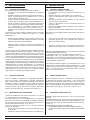
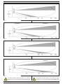
MONTAGGIO CORRETTO
Montare il rilevatore in posizione verticale e perpendicolarmente
al terreno.
MONTAGGIO NON CORRETTO (rilevatore inclinato
verticalmente)
Se il rilevatore viene montato inclinato verso il basso la portata
può risultare ridotta.
MONTAGGIO NON CORRETTO (rilevatore inclinato
verticalmente)
Se il rilevatore viene montato inclinato verso l’alto il PIR basso
non garantisce la copertura in prossimità del suolo mentre il
PIR superiore copre una zona troppo alta.
CORRECT INSTALLATION
Position the detector vertically and perpendicularly to the ground
WRONG INSTALLATION (detector tilted downwards)
If the detector is not installed perpendicularly to the ground, as
shown, operational reliability may result decreased.
WRONG INSTALLATION (detector tilted upwards)
If the detector is mounted tilted upwards, the low PIR does not
guarantee coverage close to the ground while the upper PIR
covers a too high area.

9
LINCE ITALIA
Fig. 11
Fig. 12
Fig. 13
MONTAGGIO NON CORRET-
TO
Accertarsi che il rilevatore sia
montato perpendicolarmente
rispetto al terreno.
Il rilevatore è equipaggiato con
speciali ltri per i disturbi dei
raggi solari; nei limiti del pos-
sibile è comunque consigliata
l’installazione evitando il sole
diretto
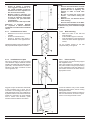
3.3.3 Regolazione della distanza di rilevazione
Tramite il pomello di regolazione è possibile regolare il fascio del
PIR basso in modo da ottenere distanze di rilevazione come di
seguito riportate.
Posizione PIR2 Distanza
A3 m
B4 m
C7 m
D15 m
PIR2 Position Range
A3 m
B4 m
C7 m
D15 m
Fig. 14
Posizione A
WRONG INSTALLATION
Take care to install the detector
perpendicularly to the groung.
The detector is designed to
avoid any light disturbance.
However too strong light as di-
rect sunlight may cause unsta-
ble condition of detector.
It’s recommended to avoid
such type of installation.
3.3.3 Detection range adjustment
Use adjusting knob to adjust PIR2 detection length.
Position A

LINCE ITALIA
10
La portata riportata è riferita ai rilevatori con 2 PIR che
diventa di 12 m nel caso del 9502-GOLD-BOBBY-AM.
The reported ow rate refers to 2 PIR detectors which
becomes 12 m in the case of 9502-GOLD-BOBBY-AM.
Fig. 15
Posizione B Position B
Fig. 16
Posizione C Position C
Fig. 17
Posizione D Position D
Fig. 18
Posizione E
Position E

11
LINCE ITALIA
4. MEMORIZZAZIONE
Prima di installare la periferica procedere alla memorizzazione
seguendo i passi riportati di seguito:
1. impostare la centrale GOLD 869 o il modulo TX/RX GOLD
869 in apprendimento periferiche facendo riferimento al
relativo manuale;
2. inserire la pila in dotazione nella propria sede;
3. premere per tre volte il microswitch antisabotaggio per
inviare la trama di memorizzazione.;
4. a convalida dell’effettiva memorizzazione del dispositivo in
centrale, il LED sulla periferica emette un lampeggio lungo;
attendere che sulla centrale venga visualizzato il messaggio
della modica dei parametri come termine della procedura
di memorizzazione.
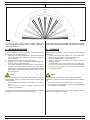
Fig. 19
Le zone in grigio non possono essere coperte; le
zone tratteggiate potranno essere coperte ruotando il
meccanismo interno.
Greyzonescan not be protected; thecoverageofdashed
zones can be obtained with rotation of internal mechanism.
3.4 GRAFICO DI COPERTURA (vista in pianta) 3.4 COVERED AREA PATTERN (plan view)
4. STORAGE
Before install the device proceed to storage it by following the
steps below:
1. set the control panel GOLD 869 or TX / RX module GOLD
869 in the storage mode by referring to the manual;
2. insert the supplied battery in the proper seat
3. Press for three times the tamper microswitch to send the
storage message;
4. as conrmation of the device storare in the control panel,
the LED on the device ashes long; wait until the parameter
change message appears on the control panel as the end of
the storage procedure.
NOTA:
Nel caso la periferica fosse già stata memorizzata si avrà una
seganalazione diversa a seconda della revisione rmare dalla
centrale stessa:
• se la centrale ha una revisione di rmware 1.xx emette un
suono;
• dalla revisione 2.xx in poi sul display compare la voce
“periferica già presente”.
Se si desidera riportare la periferica alle impostazioni di fabbrica
premere per 10 volte il microswitch antisabotaggio.
NOTE:
If the device has already been stored it will have a different
segnalation depending on the revision signed by the control pa-
nel:
• If the control panel has a rmware version 1.xx, it sounds;
• from revision 2.xx onwards the “peripheral device already pre-
sent” appears on the display.
If you want to return the device to the factory settings, press the
antitamper microswitch for 10 times

LINCE ITALIA
12
Fig. 20
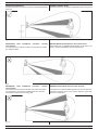
5. ESEMPIO DI RILEVAMENTO
L’esempio si riferisce al rilevatore settato in triplo AND.
( 1 ) NESSUN ALLARME
L’animale viene rilevato da due delle tre tecnologie (PIR basso
e MW) per cui l’allarme NON si attiva.
5. DETECTING EXAMPLE
The example refers to the detector set in triple AND.
( 1 ) NO ALARM
The pet is detected only by two of the three sensor elements
(PIR low and MW). The alarm is not enabled.
Fig. 21
( 2 ) NESSUN ALLARME
La persona viene rilevata da due delle tre tecnologie (PIR alto e
MW) per cui l’allarme NON si attiva.
( 2 ) NO ALARM
The body is detected only by two of the three sensor elements
(PIR high and MW). The alarm is not enabled.
Fig. 22
( 3 ) ALLARME
La persona viene rilevata da tutte e tre le tecnologie (PIR basso
+ PIR alto + MW) per cui si attiva lo stato di allarme.
( 3 ) ALARM
The body is detected by the three sensor elements (PIR low +
PIR high + MW). The alarm is enabled

13
LINCE ITALIA
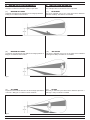
Fig. 23
6. ACCESSORI DISPONIBILI
6.1 STAFFA
Kit staffa da palo in acciaio inox (art. 001805/00102AA)
6. AVAILABLE ACCESSORIES
6.1 BRACKET
Inox bracket kit for pole installation (item 001805/00102AA)
Fig. 24
6.3 KIT RISCALDATORE
Kit riscaldatore universale equipaggiato
con sensore di temperatura ed
igrometro. Assorbimento max. 300 mA
(art.1819KR-KIT).
Disponibile anche con il solo sensore di
temperatura (art. 1821KR-KIT/E).
Collegare esclusivamente in parallelo
all’alimentazione WIN.
Non collegarlo in parallalo alla batteria
principale, ne a quella ausiliaria al ne
di non compromettere l’autonomia del ri-
levatore.
6.3 HEATER KIT
Heater kit with hygrometer and
temperature sensor. Absorption max.
300 mA (art. 1819KR-KIT).
Also aviable only with temperature
sensor (Art. 1821KR-KIT/E).
Contect only to the WIN power supply.
Not connect neither to the main bat-
tery or to the auxiliary in order to not
compromise the autonomy of the de-
vice
Fig. 25
6.2 COVER PARAPIOGGIA
Cover parapioggia per la protezione
del rilevatore dagli agenti atmosferici
(art. 1966-COVERKIT).
Accessorio consigliato in ambienti
esterni dove la pioggia che si posa
sulla lente possa diminuire drastica-
mente la portata di rilevazione.
6.2 RAIN COVER
Rain cover for the protection of the
detector against weathering (Item:
1966-COVERKIT).
Accessory recommended for outdoor
where the rain on the lens can drastically
decrease the detection range.

LINCE ITALIA
14
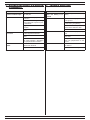
7. RICERCA DEI GUASTI E/O MALFUN-
ZIONAMENTI
Problema Soluzione
I LED non si accendono
appena installata la pila
Vericare la corretta installazio-
ne della pila
Falsi allarmi Il rilevatore non è perpendicolare
al terreno
Il PIR basso è mal regolato, rag-
giunge distanze superiori a quel-
le desiderate
Oggetti in movimento nell’area
protetta.
La sensibilità della MW è al mas-
simo
Non rileva Errata regolazione dei PIR
La sensibilità della MW è al mi-
nimo
Altezza di installazione diversa
da quella indicata o dispositivo
non perpendicolare al terreno
Allarmi continui del
MASK
Ostacoli di medie dimensioni a
ridosso del rilevatore
Regolare la sensibilità AM
Trouble Solution
LEDs fail to switch on
when the battery is in-
stalled
Check the right installation of the
battery
False alarms The detector is not perpendicular
to the ground
Check if the lower detection area
is wider than your planning
Check if there are objects in mo-
vement in the detection area.
MW is set at maximum level
No detection The PIRs are not properly adju-
sted
MW adjustment is set at mini-
mum level
Wrong installation height ord
evice non perpendicula to the
ground
Continuous of MASK Medium-sized obstacles close to
the detector
Adjust the AM sensibility
7. TROUBLE SHOOTING

15
LINCE ITALIA
8. MANUTENZIONE E VERIFICHE PE-
RIODICHE
Per assicurare il corretto funzionamento del rilevatore è ne-
cessario che la lente venga mantenuta pulita. Una lente non
perfettamente pulita può causare problemi di rivelazioni e/o
problemi alla funzione antimask.
Periodicità: quando necessario o in condizione di sporcizia evi-
dente.
Materiale da utilizzare: panno - acqua senza additivi.
Procedura di pulizia:
ATTENZIONE! Per rimuovere sporcizie particolar-
mente evidenti NON utilizzare prodotti a base di clo-
ro, prodotti abrasivi oppure alcool.
1. Pulire il coperchio e la lente con un panno inumidito con ac-
qua.
2. Ripassare con un panno asciutto.
9. SMALTIMENTO E ROTTAMAZIONE
9.1 SMALTIMENTO IMBALLAGGIO
Smaltire il materiale di imballo secondo i codici identicativi
riportati sul materiale stesso:
• PAP 20 / PAP 21 – raccolta differenziata carta;
• PVC 3 / LDPE 4 / O 7 – raccolta differenziata plastica.
Vericare il sistema di raccolta del proprio comune.
9.2 SMALTIMENTO PRODOTTO E ROTTAMAZIONE
1. Svitare il fondo, rimuovere la pila e tutte le parti del prodotto
quali scheda e contenitore plastico;
2. Dividere le parti in base alla loro tipologia e smaltirle in ac-
cordo con le leggi vigenti.
ATTENZIONE!
Non disperdere nell’ambiente i componenti ed ogni
altro materiale del prodotto. Rivolgersi a consorzi
abilitati allo smaltimento ed al riciclaggio dei materiali.
9. DISPOSAL AND SCRAPPING
9.1 DISPOSAL OF PACKAGING
Dispose of the packaging material according to the identication
codes shown on the material itself:
• PAP 20 / PAP 21 - separate paper collection;
• PVC 3 / LDPE 4 / O 7 - plastic separate collection.
Check your municipality's collection system.
9.2 PRODUCT DISPOSAL AND SCRAPPING
1. Unscrew the bottom, remove the battery and all parts of the
product such as the board and plastic case;
2. Divide the parts by type and dispose of them in accordance
with applicable laws.
IMPORTANT!
Do not dispose of the components or any other pro-
duct material in the environment. Seek the assistan-
ce of companies authorised to dispose of and recycle waste
materials.
8. MAINTENANCE AND PERIODIC
CHECKS
Keep the lens clean to guarantee proper operation of the
detector.
A lens which is not perfectly clean may cause detection pro-
blems and/or problems to the anti-mask function.
Frequency: when necessary or when clearly dirty.
Material to be used: cloth - water with no additives.
Cleaning procedure:
IMPORTANT!
Do NOT use chlorine-based or abrasive products or
alcohol to remove particularly noticeable dirt.
1. Clean the lid and the lens with a cloth dampened with water.
2. Wipe with a dry cloth.

001530/00859AC REV0
LINCE ITALIA S.r.l.
Via Variante di Cancelliera, snc
00072 Ariccia (Roma)
Tel. +39 06 9301801
Fax +39 06 930180232
www.lince.net
-
 1
1
-
 2
2
-
 3
3
-
 4
4
-
 5
5
-
 6
6
-
 7
7
-
 8
8
-
 9
9
-
 10
10
-
 11
11
-
 12
12
-
 13
13
-
 14
14
-
 15
15
-
 16
16


Lince 9553-GOLD-BOBBY-AM-E Istruzioni per l'uso
- Categoria
- Illuminazione di comodità
- Tipo
- Istruzioni per l'uso
- Questo manuale è adatto anche per
in altre lingue
Documenti correlati
-
 Lince 1673BOBBY Istruzioni per l'uso
-
 Lince 1897BOBBY-AM/UE Istruzioni per l'uso
-
 Lince 1875BOBBY-AM/E Istruzioni per l'uso
-
 Lince 1947-BOBBY180-E-AM Istruzioni per l'uso
-
 Lince 9557-GOLD-OUT Istruzioni per l'uso
-
 Lince 1597ZENITHDT Istruzioni per l'uso
-
 Lince 4058GR868DT Istruzioni per l'uso
-
 Lince 4059GR868ZENITH Istruzioni per l'uso
-
 Lince 9560-GOLD-SAXA Istruzioni per l'uso
-
 Lince 1883ZENITHDT/E Istruzioni per l'uso


Altri documenti
-
Ksenia velum DT + AM User And Installer Manual
-
 Elkron TT19AM Guida d'installazione
-
 Elkron TT20AM Guida d'installazione
-
 Elkron TTR619AM Manuale utente
-
 Elkron DT17 Guida d'installazione
-
Vimar 03835 Manuale utente
-
-
 Elkron DT15AM Guida d'installazione
-
Risco WatchOUT XTreme 315DT Installation Instructions Manual
-
 MO-EL PALO XL 4688 Manuale del proprietario


