Key Automation 580ISCT-101 Manuale utente
- Tipo
- Manuale utente

IT
GB
F
D
E
P
PL
NL
MANUALE ISTRUZIONI
INSTRUCTION MANUAL
MANUEL D'EMPLOI
BEDIENUNGSANLEITUNG
MANUAL DE INSTRUCCIONES
MANUAL DE INSTRUÇÕES
INSTRUKCJA OBSŁUGI
GEBRUIKSHANDLEIDING
Centrale elettronica
Electronic control unit
Centrale électronique
Elektronische Steuereinheit
Central electrónica
Central electrónica
Elektroniczna jednostka sterująca
Electrische zekering
900CT-101
Key Automation S.p.A

2
ITALIANO
ATTENZIONE:
Leggere attentamente le istruzioni prima di eseguire l’installazione.
La non osservanza delle suddette istruzioni, l’uso improprio o un errore di collega-
mento potrebbe pregiudicare la sicurezza o il corretto funzionamento del dispositivo,
e quindi dell’intero impianto. Si declina ogni responsabilità per eventuali malfunziona-
menti e/o danni dovuti derivanti dalla loro inosservanza.
ATTENZIONE
I dati e le informazioni indicate in questo manuale sono da ritenersi suscettibili di modica in qualsi-
asi momento e senza obbligo di preavviso da parte di Key Automation S.r.l.
ATTENZIONE:
Gli impianti elettrici e le automazioni devono essere eseguite da personale esperto e qualicato nel
rispetto delle norme di legge.
Tutti i collegamenti devono essere eseguiti con alimentazione di rete non presente.
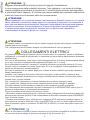
COLLEGAMENTI ELETTRICI
Per garantire l’incolumità dell’operatore e per prevenire danni ai componenti, mentre si effettuano i
collegamenti, o si innesta la scheda radio, la centralina non deve essere assolutamente alimentata
elettricamente.
Per i cavi di alimentazione, linee motori, linea lampeggianti/luce di cortesia, elettroserratura utilizza-
re un cavo con sezione adeguata alla lunghezza del tragitto.(min 1,5 mmq).
Per le alimentazioni ausiliarie i comandi e i contatti di sicurezza una sezione minima di 0,5 mmq.
Quando i cavi di comando sono molto lunghi (oltre 30 m) è consigliabile il disaccoppiamento me-
diante dei relè presso la centralina stessa.
Nel caso di intervento di un fusibile, dopo aver rimosso la causa sostituirlo con un altro avente le
stesse caratteristiche.
Installare i vari dispositivi di sicurezza, necorsa, fotocellule, costa sensibile, pulsante di stop.
Se uno o più dispositivi di sicurezza non vengono installati devono essere cortocircuitati i relativi
morsetti con il comune comandi.
Tutti i contatti N.C. Abbinati ad uno stesso ingresso devono essere collegati in serie.
Tutti i contatti N.A. Abbinati ad uno stesso ingresso devono essere collegati in parallelo.
Prevedere elementi di disconnessione dalla rete di alimentazione su posto accessibile.
Per l’alimentazione della centralina è previsto l’inserimento di un SEZIONATORE esterno (non in
dotazione) indipendente e correttamente dimensionato.
Prima di procedere all’attivazione del motore si chiede :
• Sbloccare il motore meccanicamente e vericare l’esatto collegamento dei necorsa in base all’a-
pertura ed alla chiusura dell’anta, il led corrispondente al necorsa interessato deve SPEGNERSI
con il necorsa attivato
• Chiudere manualmente l’anta, effettuare ora un impulso di P/P premendo il pulsante relativo; la
prima manovra che deve effettuare l’anta è una APERTURA, se così non fosse togliere alimenta-
zione all’impianto e girare il connettore JP4 MOTOR (N.19/20/21) in modo da invertire l’apre con il
chiude.
ATTENZIONE:
Questo apparecchio non è destinato a essere usato da persone (Bambini compresi) le cui capacità
siche, sensoriali o mentali siano ridotte, oppure con mancanza di esperienza o di conoscenza, a
meno che esse abbiano potuto beneciare, attraverso l’intermediazione di una persona responsa-
bile della loro sicurezza, di una sorveglianza o di istruzioni riguardanti l’uso dell’apparecchio.
-I bambini devono essere sorvegliati per sincerarsi che non giochino con l’apparecchio;
-Non permettere ai bambini di giocare con i comandi.

3
ITALIANO
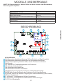
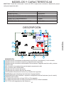
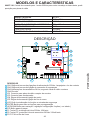
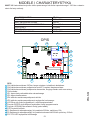
MODELLI E CARATTERISTICHE
900CT-101 con predisposizione per scheda radio.
La centrale di comando 900CT-101 è destinata al comando di un motore asincrono monofase uti-
lizzato per automatizzare il movimento di uno scorrevole o di un basculante.
Ogni altro uso è improprio e vietato.
DATI TECNICI CT-101
ALIMENTAZIONE 230Vac/50Hz
CARICO MAX MOTORE 1200 W
USCITA ALIMENTAZIONE ACCESSORI 24Vac 400mA
TEMPO LAVORO 0-120sec
TEMPO PAUSA 0-120sec
TEMPERATURA DI FUNZIONAMENTO -20°C/+70°C
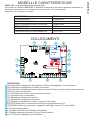
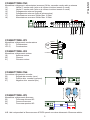
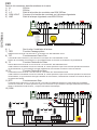
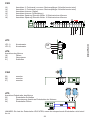
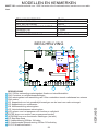
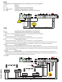
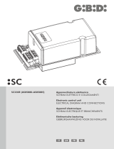
COLLEGAMENTI
DESCRIZIONE
CN1 Morsettiera collegamenti alimentazione 230Vac, lampeggiante e luce di cortesia
CN2 Morsettiera collegamento comandi e sicurezze
CN3 Morsettiera collegamento alimentazioni accessori 24Vac, secondo canale radio e antenna
CN4 Connettore per encoder
JP1 Connettore per scheda radio ricevente ad innesto
JP3 Connettore per condensatore
JP4 Morsettiera collegamento motore
JP5 Morsettiera collegamento necorsa
LCD Display di segnalazione funzioni e ingressi di sicurezza
ENTER Pulsante per lo scorrimento funzioni per la programmazione P2
UP/DOWN Pulsante per variazione / regolazione settaggio funzioni P1( vedi tabella )
P/P Pulsante passo passo
F1 Fusibile protezione linea 230Vac 10A ritardato
F2 Fusibile protezione accessori 230Vac 315mA ritardato
FCC FCA Led di segnalazione dei necorsa
14
13
12
11
10
9
8
7
6
5
4
3
2
1
15
1 2 3 4 5
9
2
8
7
1
13
14
6
3
4
--
. .
6 7 8 9 10 11 12 13 14 15 16 17 18
22 23 24
21
20
19
25 26 27
5
12
11
10
15

4
ITALIANO
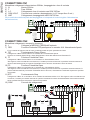
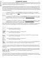
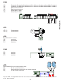
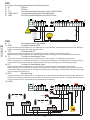
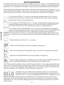
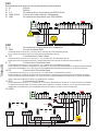
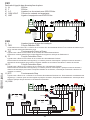
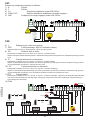
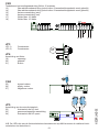
CONNETTORE CN1
Morsettiera collegamenti alimentazione 230Vac, lampeggiante e luce di cortesia
1) N Neutro 230Vac
2) F Fase 230Vac
3) L.C. Collegamento luce di cortesia max.25W 230Vac
4) COM LC/LP Comune luce cortesia e lampeggiante ( in LC tempo sso 2 min )
5) LMP Collegamento lampeggiante max.25W 230Vac
Per la sostituzione della lampada del lampeggiante o la lampada di cortesia togliere l’alimentazione
dell’automazione;
CONNETTORE CN2
Morsettiera collegamento comandi e sicurezze
6) $ Collegare la MESSA A TERRA dell’impianto
7) PED Funzione Pedonale PED predisporre un contatto N.A. Normalmente Aperto
E’ un comando di apertura che nel caso sia attivato andrà ad aprire parzialmente l’anta.
8) P/P Funzionamento Passo /Passo
Collegato tra il Mors.N.8 ed il Mors.N.12 Contatto N.A. Normalmente Aperto
Ingresso di comando Apre/Chiude o Apre/Stop/Chiude in base alla selezione del Parametro D
9) F1 Funzione Fotocellula Close
Collegata tra il Mors.N.9 ed il Mors. N.12 Contatto N.C. Normalmente Chiuso
Tale ingresso viene considerato una sicurezza, il contatto può essere interrotto in qualsiasi momento durante la
chiusura dell’automazione provocando l’immediato blocco del moto invertendo il senso di marcia
10) F2 Funzione Fotocellula Open
Collegata tra il Mors.N.10 ed il Mors.N.12 Contatto N.C. Normalmente Chiuso
Tale ingresso viene considerato una sicurezza, il contatto può essere interrotto in qualsiasi momento durante l’a-
pertura dell’automazione provocando l’immediato blocco del moto, l’automazione continuerà l’apertura al ripristino
del contatto.
11) STP Funzionamento Stop
Collegato tra il Mors. N.11 ed il Mors. N.12 Contatto Normalmente Chiuso N.C. Tale ingresso viene considerato una
sicurezza; il contatto può essere interrotto in qualsiasi momento bloccando immediatamente l’automazione disabili-
tando qualsiasi funzione compresa la Chiusura Automatica
12) COM Comune dei collegamenti
RG58
230Vac
Luce
cortesia
Lampeggiante
1 2 3 4 5 6 7 8 9 10 11 12 13 14 15 16 17 18
Antenna
NA PED
NA P/P
NC STOP
COMUNE
Antenna
Alim. accessori
1 2 3 4 5 6 7 8 9 10 11 12 13 14 15 16 17 18
3
TX RX
34
NC
F1
3
TX RX
34
NC
F2
1212
1212
24Vac/dc
- +
24Vac/dc
- +
24Vac/dc
- +
24Vac/dc
- +

5
ITALIANO
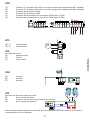
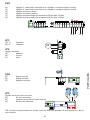
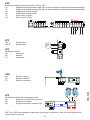
CONNETTORE JP3
Morsettiera collegamento condensatore
JP3 1) Condensatore
JP3 2) Condensatore
CONNETTORE JP4
Morsettiera collegamento motore
19) Apertura motore
20) Comune
21) Chiusura motore
CONNETTORE CN4
Connettore collegamento encoder
25) Segnale da encoder (nero)
26) Positivo alim. encoder (marrone)
27) Negativo alim. encoder (blu)
CONNETTORE JP5
Morsettiera collegamento necorsa
22) Finecorsa chiusura NC
23) Comune necorsa
24) Finecorsa apertura NC
N.B. i led corrispondenti ai necorsa sono ACCESI quando non viene interessato il necorsa relativo.
CONNETTORE CN3
Morsettiera collegamento alimentazioni accessori 24Vac, secondo canale radio e antenna
13) Uscita 2° canale radio (solo se si utilizza ricevitore innesto 2 canali)
14) Uscita 2° canale radio (solo se si utilizza ricevitore innesto 2 canali)
15) Collegamento antenna (segnale)
16) Collegamento antenna (calza di schermatura)
17) Alimentazione accessori 24Vac Max 10 Watt
18) Alimentazione accessori 24Vac Max 10 Watt
Condensatore
M
Motore 21
20
19
Antenna
Alim. accessori
1 2 3 4 5 6 7 8 9 10 11 12 13 14 15 16 17 18
Uscita 2° canale
NC Finecorsa APRE
NC Finecorsa CHIUDE
COMUNE
22 23 24
25 26 27
NO

6
ITALIANO
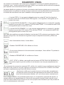
DIAGNOSI VISIVA
La centrale di comando è stata progettata per automatizzare aperture residenziali ed industriali ad
1 motore con potenza massima di 1200W con controlli di sicurezza attivi e passivi per ottenere una
installazione conforme alle vigenti normative di sicurezza.
La grande afdabilità del sistema e l’alta concentrazione delle funzioni che vengono gestite da un
microcontrollore fanno si che il sistema possa calcolarsi tutti i parametri di rallentamento ed il tem-
po di lavoro autonomamente senza nessuna programmazione particolare da parte dell’installatore.
La centrale viene già fornita con una programmazione base che vi permette di avere già i parametri
fondamentali selezionati
• L’ingresso STOP N°11 in cui è obbligatorio l’utilizzo di un contatto N.C. deve essere
chiuso e i due puntini del LCD NON devono lampeggiare, se lampeggiano vuol dire che il
contatto è aperto.
• L’ingresso FOTO APRE F2 N°10 in cui è obbligatorio l’utilizzo di un contatto N.C. deve
essere chiuso e il puntino del LCD di sinistra F2OP deve essere SPENTO, se risultasse
ACCESO FISSO vuol dire che il contatto è aperto.
• L’ingresso FOTO CHIUDE F1 N°9 in cui è obbligatorio l’utilizzo di un contatto N.C. deve
essere chiuso e il puntino del LCD di destra F1CL deve essere SPENTO, se risultasse
ACCESO FISSO vuol dire che il contatto è aperto.
N.B. I puntini del LCD in condizioni di normale utilizzo non devono ne lampeggiare ne essere acce-
si ssi, si accendono o lampeggiano nel caso in cui intervenga la sicurezza corrispondente.
• Con automazione chiusa visualizza.
led FCC spento FCA acceso
• Durante l’APERTURA sul display si visualizza OP.
led FCC acceso FCA acceso
• Se si è selezionato il funzionamento Automatico visualizza TC nel tempo di pausa.
led FCC acceso FCA spento
• Durante la CHIUSURA sul display si visualizza CL.
led FCC acceso FCA acceso
• Se si visualizza ST ( stop ) vuol dire che si è abilitata la funzione UOMO PRESENTE e
non si è terminato il ciclo di apertura o chiusura completa (parametro U1)
N.B. ad ogni variazione di qualsiasi parametro la centrale effettua, al primo impulso di start l’ap-
prendimento del tempo di lavoro da cancello chiuso ad aperto tra i due necorsa, solo dopo questa
manovra si potranno vedere i rallentamenti (se sono stati abilitati).
• Tramite un nuovo comando di P/P vericare che si effettui l’apertura completa dell’anta sino al
necorsa, a questo punto ripremere il pulsante P/P e vericare la completa chiusura dell’anta sino
al necorsa.
• Dopo aver vericato l’esatto funzionamento di apertura e chiusura completa
possiamo andare ad abilitare il rallentamento in base alla percentuale voluta
( parametro E ) e la Forza motore massima ( parametro L )

7
ITALIANO
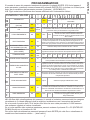
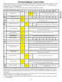
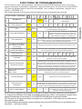
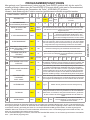
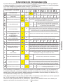
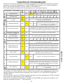
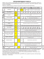
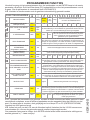
FUNZIONI / VALORI
SENSIBILITÀ -- Alta Medio
Alta
Medio
Bassa Bassa
Selezione rilevamento ostacoli attivo solo
con parametro L=0 e motore con sensore
ENCODER.
CHIUSURA AUTOMATICA
(secondi) NO 5 10 15 20 25 30 40 80 120
COMANDO PASSO PASSO
P/P
Apre
Stop
chiude
Apre
Chiude
Modicando il valore P/P si cambia il funzionamento dell’automazione
come descritto dalle funzioni; si ricorda che la funzione Apre chiude
può essere critica per automazioni con grandi inerzie.
% RALLENTAMENTO NO 10% 20% 30%
Attivando la funzione Rallentamento negli ultimi
secondi di funzionamento dell’automazione la
centrale comanda i motori a velocità ridotta in base
alla % scelta
ELETTROFRENO NO SI
Attivando la funzione Elettrofreno (se presente) tramite il parametro
F,si riesce a impedire che un cancello pesante,in seguito ad un co-
mando o ad intervento di una sicurezza, a causa dell’inerzia continui il
movimento per qualche secondo invece di bloccarsi immediatamente
SELEZIONE TEMPO LAVO-
RO MASSIMA (secondi) 90 180 Selezione tempo lavoro massima 90 sec / 180 sec
CONDOMINIALE
(SOLO APRE) NO SI Attivando la funzione condominiale facciamo in modo che il primo
impulso di P/P apre ed accetta solo la riapertura durante la chiusura
FORZA MOTORE 100%
Max
10%
Min 20% 30% 40% 50% 60% 70% 80% 90%
CHIUDE DOPO TRANSITO NO SI
Attivando la funzione Chiude dopo Transito con chiusura automatica
inserita facciamo in modo che l’automazione si chiuda nel tempo più
breve possibile senza attendere la richiusura automatica
TIMER/SPIRA MAGNETICA
SU P/P NO SI
Attivando la funzione Timer / Spira magnetica, dopo aver terminato
l’apertura totale se si mantiene chiuso il contatto di P/P N.8 si blocca
il tempo di chiusura automatica in modo che il cancello non si chiuda
mai sino alla nuova apertura del contatto di P/P, nel caso intervenisse-
ro vari impulsi di P/P durante il tempo di attesa della chiusura automa-
tica il tempo viene continuamente riazzerato
PARTENZA RALLENTATA
SOFT START NO SI
Attivando la funzione Soft Start nei primi secondi di movimento dell’au-
tomazione la centrale comanda il motore a velocità ridotta per avere
una partenza più dolce.
TIPOLOGIA MOTORE -- Tipo 1 Tipo 2 Selezione tipologia rallentamento voluta
UOMO PRESENTE NO SI
Attivando la funzione uomo presente tramite il parametro U si ha la
possibilità di far APRIRE l’automazione chiudendo il contatto di P/P
N.8 e far CHIUDERE l’automazione chiudendo il contatto PED N.7; al
rilascio dei due contatti l’automazione si posiziona in STOP
PRELAMPEGGIO NO 1sec 2sec 4sec
Attivando la funzione Prelampeggio prima di ogni
movimento il lampeggiante viene attivato per il
tempo selezionato
NB. Alla ne della visualizzazione dei parametri si accede al contatore manovre totali che vengono
visualizzate in 2 videate differenti dove le migliaia si evidenziano con l’accensione del puntino:
Se si accende il puntino del LCD di sinistra vuol dire che sono state passate le 10.000 manovre
che andranno aggiunte al valore visualizzato.
Se si vuole azzerare tale contatore mantenere premuto assieme il pulsante P1 e P2 (ENTER/UP-
DOWN) nché non si visualizza 0.0 00
Per uscire dalla visualizzazione parametri premere il tasto ENTER più volte no a visualizzare la
condizione di automazione chiusa - - ( due trattini ).
PROGRAMMAZIONE
Si accede al menu dei parametri mantenendo premuto il pulsante ENTER (P2) nché appare il
primo parametro, premendo consecutivamente il pulsante ENTER (P2) si avanza con il menù para-
metri, per la variazione del parametro premere il pulsante ↕ UP/DOWN (P1)
N.B. Ogni variazione di funzione deve essere effettuata con l’automazione chiusa

8
ITALIANO
REGOLAZIONE FORZA MOTORI
Dopo uno spunto di 1,5 Secondi si inserisce il controllo di Forza elettronica in cui si parzializza la
tensione di alimentazione regolandone il valore tramite il parametro L.
N.B. riferirsi per i carichi di spinta massima alle normative vigenti.
ATTENZIONE:
dopo 3 rilevazioni d’ostacolo consecutive, il cancello si ferma in apertura e viene esclusa la chiu-
sura automatica; per riprendere il movimento bisogna premere il pulsante di comando o usare il
trasmettitore.
CONNETTORE RADIO
La centrale CT-101 è compatibile con i seguenti ricevitori Key Automation della serie MEMO ad
innesto: 900RXI-22 / 900RXI-42 / 900RXI-42R
AVVERTENZE FINALI
• L’installazione dell’automazione deve essere eseguita a regola d’arte da personale qualicato
avente i requisiti di legge e fatta in conformità delle direttive vigenti.
• Vericare la solidità delle strutture esistenti (colonne, cerniere, ante) in relazione alle forze svilup-
pate dal motore.
• Vericare che vi siano dei fermi meccanici di adeguata robustezza a ne apertura e ne chiusura
delle ante.
• Fare un’analisi dei rischi dell’automazione e di conseguenza adottare le sicurezze e le segnala-
zioni necessarie.
• Installare i comandi (ad esempio il selettore a chiave) in modo che l’utilizzatore non si trovi in una
zona pericolosa.
• Terminata l’installazione provare più volte i dispositivi di sicurezza, segnalazione e di sblocco
dell’automazione.
• Applicare sull’automazione l’etichetta o la targhetta CE contenenti le informazioni di pericolo e i
dati di identicazione.
• Consegnare all’utilizzatore nale le istruzioni d’uso, le avvertenze per la sicurezza e la dichiara-
zione CE di conformità.
• Accertarsi che l’utilizzatore abbia compreso il corretto funzionamento automatico, manuale e di
emergenza dell’automazione.
• Informare l’utilizzatore per iscritto (ad esempio nelle istruzioni d’uso) dell’ eventuale presenza di
rischi residui non protetti e dell’uso improprio prevedibile.
• Predisporre un piano di manutenzione dell’impianto (almeno ogni 6 mesi per le sicurezze) ripor-
tando su di un apposito registro gli interventi eseguiti.
• Conservare il presente manuale d’istruzioni per future consultazioni.
• La ditta Key Automation S.r.l. si riserva la facoltà insindacabile di apportare, in qualsiasi momento,
le modiche che si rendessero necessarie ai ni di un miglioramento estetico e/o funzionale.
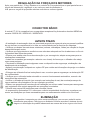
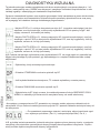
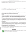
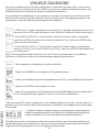
SMALTIMENTO
Questo prodotto è formato da vari componenti che potrebbero a loro volta contenere
sostanze inquinanti. Informarsi sul sistema di riciclaggio o smaltimento del prodotto atte-
nendosi alle norme di legge vigenti a livello locale.
NON DISPERDERE NELL’AMBIENTE!

NOTE ANMERKUNGEN
NOTES NOTA
NOTES OBSERVAÇÕES

10
ENGLISH
WARNING:
It is advisable to read the instructions carefully before you start installation.
Failure to comply with these instructions, improper use or incorrect connection may compromise
the safety or correct operation of the device and hence of the entire system.
No liability shall be accepted for any malfunctions and/or damage due to failure to comply with the
instructions.
The company reserves the right to make improvements to the products.
THIS BOOKLET IS TO BE USED ONLY BY THE INSTALLER
Installation must be carried out only by professionally qualied personnel in compliance with cur-
rent legal requirements.
ELECTRICAL CONNECTIONS
To ensure operator safety and to prevent damage to the components while connections are being
made, or when the radio card is being inserted, the control unit absolutely must not be powered on.
For power cords, motor lines, asher/courtesy light line, and electric lock, use a cable with a cross-
section that is suitable for the length (minimum 1.5 mm2).
For auxiliary power supplies, controls and safety contacts a minimum section of 0,5 mm2. When
the control cables are very long (more than 30 m), de-coupling is suggested using relays at the
control unit.
If a fuse trips, after removing the cause, replace it with another one of the same type. Install the
various safety devices, limit switches, photocells, sensitive rib, stop button.
If one or more of the safety devices are not installed, the corresponding terminals must be short
circuited with the controls common.
All contacts N.C. Assigned to the same input must be connected in series.
All contacts N.O. Assigned to the same input must be connected in parallel.
Provide disconnecting devices in the power supply network in accessible places.
For the power supply of the control unit, there must be an external disconnecting switch (not includ-
ed), independent and properly sized.

11
ENGLISH
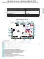
MODELS AND CHARACTERISTICS
900CT-101 Control unit for 1 230 Vac motor sliding or overhead motor, set up for radio card.
TECHNICAL DATA CT-101
POWER SUPPLY 230Vac/50Hz
MAX. MOTOR LOAD 1200 W
ACCESSORIES POWER SUPPLY OUTPUT 24Vac 400mA
WORKING TIME 0-120sec
PAUSE TIME 0-120sec
OPERATING TEMPERATURE -20°C/+70°C
DESCRIPTION
DESCRIPTION
CN1 230Vac power supply terminal board, asher and courtesy light
CN2 Controls and safeties connection terminal board
CN3 Terminal board for connection of 24Vac accessories second radio channel and antenna
CN4 encoder
JP1 Connector for snap-in radio receiving card
JP3 Connector for capacitor
JP4 Motor connection terminal board
JP5 Limit switch connection terminal board
LCD Display for signalling functions and safety inputs
ENTER button for scrolling programming functions
UP/DOWN button for function settings (see table)
P/P Step/step button
F1 line protection 230Vac 10A delayed
F2 accessory line protection 230Vac 315mA delayed
FCC FCA Led limit switch
1 2 3 4 5
9
2
8
7
1
13
14
6
3
4
--
. .
6 7 8 9 10 11 12 13 14 15 16 17 18
22 23 24
21
20
19
25 26 27
5
12
11
10
15
14
13
12
11
10
9
8
7
6
5
4
3
2
1
15

12
ENGLISH
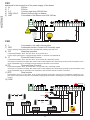
RG58
230Vac
1 2 3 4 5 6 7 8 9 10 11 12 13 14 15 16 17 18
CN1
dedicated to the connection of the power supply of the board:
1) N 230Vac
2) F 230Vac
3) L.C. Courtesy light max.25W 230Vac
4) COM LC/LP Shared courtesy light or asher
5) LMP Connected to the asher max.25W 230Vac
CN2
6) $ Connected to the earth of the system
7) PED Pedestrian function Contact N.O. Normally open
It is an opening command which when activated will partially open the door.
8) P/P Step/step operation
Connected between Term. N.8 and Term. N.12 Contact N.O
Control input open/close or open/stop/close based on selection of parameter D
9) F1 Photocell Close Function
Connected between Term. N.9 and Term. N.12 Contact N.C.Normally Closed
This input is considered a safety, the contact can be interrupted at any time during closing of the automation caus-
ing an immediate stop in movement and reversing the direction of movement
10) F2 Photocell Open Function
Connected between Term. N.10 and Term. N.12 Contact N.C. Normally closed
This input is considered a safety, the contact can be interrupted at any time during opening by the automation caus-
ing an immediate stop in movement, the automation will continue until the contact is restored.
11) STP Stop function
Connected to Term. N.11 and Term. N.12 Contact Normally Closed N.C. This input is considered a safety the con-
tact can be interrupted at any time immediately stopping the automation disabling any function including automatic
closing.
12) COM
NA PED
NA P/P
NC STOP
COMUNE
Antenna
Alim. accessori
1 2 3 4 5 6 7 8 9 10 11 12 13 14 15 16 17 18
3
TX RX
34
NC
F1
3
TX RX
34
NC
F2
1212
1212
24Vac/dc
- +
24Vac/dc
- +
24Vac/dc
- +
24Vac/dc
- +

13
ENGLISH
JP3
JP3 1) Capacitor
JP3 2) Capacitor
JP4
Connection of Motor
19) opening
20) shared
21) closing
CN4
25) Signal encoder
26) Supply encoder
27) Negative encoder
JP5
Motor limit switch connection
22) limit switch closing NC
23) common connection
24) limit switch opening NC
N.B. The LEDs that correspond to the limit switches are ON when the relative limit switch is not involved.
CN3
Accessory power supply connection 24Vac 15 watts max
13) 2nd radio channel connection (only if using 2-channel radio connector)
14) 2nd radio channel connection (only if using 2-channel radio connector)
15) Antenna connection (signal)
16) Antenna connection (mesh)
17) 24Vac Max 10 Watt
18) 24Vac Max 10 Watt
M21
20
19
1 2 3 4 5 6 7 8 9 10 11 12 13 14 15 16 17 18
22 23 24
25 26 27
NO

14
ENGLISH
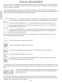
VISUAL DIAGNOSIS
The control unit is designed to automate residential and industrial openings with 1 motor having a
maximum power of 1200W with active and passive safety controls for installation that is compliant
with current safety standards.
The great reliability of the system and the high concentration of the functions are managed by a
micro-controller so that the system can autonomously calculate all deceleration parameters and the
working time with no special programming by the installer.
• STOP input no. 11 in which the use of a contact N.C. is compulsory must be closed and
the two points of the LCD must not ash. If they ash, it means that the contact is open
• The input PHOTO OPEN F2 no. 10, which requires the use of an NC contact, must
be closed and the F2OP point of the LCD on the left must be OFF. If it is on STEADY it
means that the contact is open
• The input PHOTO OPEN F1 no. 9, which requires the use of an NC contact, must be
closed and the F1CL point of the LCD on the right must be OFF. If it is on STEADY it
means that the contact is open
N.B. In normal use, the points of the LCD must not ash or be on steady. They ash or stay on if
the corresponding safety is activated.
• With the automation closed, will be shown
• During OPENING the display will show OP
• If you have selected Automatic operation, TC will be shown in the pause time
• During CLOSING the display will show CL
• If ST (stop) is shown, it means that the DEAD MAN function is enabled and the com-
plete opening or closing cycle has not ended
N.B. with each variation of any parameter the control unit will, at the rst start impulse, verify the
working time of the closed and open gate between the two stops. Only once this is carried out the
enabling of the deceleration can be veried
• By using a new P/P command check that the complete opening of the door is carried out up to the
stop. At this point press the P/P button again and check the complete closing of the door up to the
stop.
• • After having veried the correct complete opening and closing enable the
deceleration based on the desired percentage ( Par. E ) and the maximum
motor force ( Par.L )

15
ENGLISH
FUNCTIONS/VALUES
SENSITIVITY -- High Medium
High
Me-
dium
Low
Low Obstacle detection activated with L=0 and
motor with ENCODER sensor
AUTOMATIC CLOSURE
(seconds) NO 5 10 15 20 25 30 40 80 120
STEP BY STEP COMMAND
P/P
Open
Stop
close
Open
Close
By activating the step/step function, you avoid passage of the automa-
tion in the stop state. The enabled function may be critical for automa-
tions with high inertia.
% DECELERATION NO 10% 20% 30%
When the deceleration function is activated in the
last seconds of operation of the automation, the
control unit slows the motors based on the selected
%.
ELECTROBRAKE NO YES
By activating the electrobrake function through the F parameter, a
heavy gate is prevented from continuing its movement, due to its iner-
tia, for a few seconds instead of stopping it instantenously following a
command or a safety action
MAXIMUM WORKING TIME
EXTENSION
(expressed in seconds)
90 180 Maximum working time extention 90/180 seconds
CONDOMINIUM
(OPEN ONLY) NO YES Activate the condominium function so that the rst step/step impulse
opens and accepts only re-opening during closing
MOTOR FORCE 100%
Max
10%
Min 20% 30% 40% 50% 60% 70% 80% 90%
CLOSE AFTER TRANSIT NO YES
When you activate the Close After Transit function with automatic clo-
sure activated, the automation is closed in the shortest time possible
without waiting for automatic re-closing.
TIMER/MAGNETIC COIL
ON STEP/STEP NO YES
When you activate the function Timer / Magnetic Coil via parameter P
after terminating total opening if step/step contact N.8 is kept closed
the automatic closing time is locked so that the gate never closes until
the step/step contact is opened again, if there are several step/step
impulses during the standby time for automatic closing the time will be
continuously reset
SOFT START DELAYED
START TIME NO YES
When you activate the Soft Start function, during the rst seconds of
movement of the automation the control unit keeps the motor at redu-
ced speed for a softer start.
MOTOR TYPE -- Type 1 Type 2 Select the desired type of slowdown
DEAD MAN NO YES
When you activate the Man Present function via parameter U, you can
open the automation until step/step contact N.8 is closed and close the
automation until contact PED n.7 is closed; when the two contacts are
released the automation goes to STOP position.
PRE-FLASHING NO 1sec 2sec 4sec
When the pre-ashing function is activated, before
any movement the asher is activated for the
selected time
N.B.:Once the parameters have been displayed, the total manoeuvres counter are shown in two
different screens, where the thousand units are indicated by the lighting up of the point. To reset
this counter, simultaneously press and hold buttons P1 and P2 (ENTER/UP-DOWN) until 0000 is
displayed
N.B. If the point of the LCD on the left lights up, it means that 10,000 manoeuvres have been ex-
ceeded, which must be added to the value shown.
To exit parameter display, press ENTER several times until automatic closure condition is shown
(- - two dashes).
PROGRAMMING FUNCTIONS
Access the parameter menu by holding the ENTER button until the rst parameter, appears. Press
the ENTER button (P2) repeatedly to advance through the parameters menu. To change the pa-
rameter press ↕ UP/DOWN (P1)
N.B. any variation in function must be made with the automation closed

16
ENGLISH
ADJUSTMENT OF MOTOR FORCE
After a breakaway of 1,5 seconds, the electronic force control activates which distributes the power
supply, adjusting the value by means of parameter L.
N.B. for maximum thrust loads refer to current standards.
RADIO CONNECTOR
The CT-101 control unit is compatible with the following Key Automation receivers of the MEMO
snap-in series: 900RXI-22 / 900RXI-42 / 900RXI-42R
FINAL WARNINGS
• The installation of the automation must be performed properly by qualied personnel in posses-
sion of legal requirements and in compliance with machine directive.
• Check the solidity of existing structures (columns, hinges, doors) in relation to the force generated
by the motor.
• Check that there are suitably sturdy mechanical stops at the end of opening and closing travel of
the doors.
• Analyze the risks of the automation and adopt necessary safety measures and warnings.
• install controls (such as the key selector) so that the user is not in a hazardous position.
• Upon completion of installation, check the safety devices several times, as well as those for sig-
nalling and automation release.
• Provide the automation with the EC label or tag that contains the danger information and identi-
cation data.
• Give the nal user the instructions for use, safety warnings and the EC declaration of conformity.
• Make sure the user understands proper automatic, manual and emergency operation of the auto-
mation.
• Inform the user in writing (for example in the instructions for use) of any unprotected residual risks
and foreseeable improper use.
• Provide a maintenance schedule for the system (at least every 6 months for the safeties) with an
appropriate register of work performed.
• Keep this instruction manual for future reference.
• Key Automation S.r.l. reserves the right to make, at any time, any modications which may be
required to improve appearance and/or operation.
DISPOSAL
This product is composed of various components which may in turn contain pollutants.
Do not dispose of it in the environment! Find out about the method for recycling or dis-
posing of the product in compliance with current local laws

NOTE ANMERKUNGEN
NOTES NOTA
NOTES OBSERVAÇÕES

18
FRANÇAIS
ATTENTION :
Lire attentivement les instructions avant de procéder à l’installation.
Le non-respect des instructions susmentionnées, toute utilisation impropre ou toute
erreur de branchement peut nuire à la sécurité ou au bon fonctionnement du disposi-
tif et, par conséquent, à toute l’installation.
Nous déclinons toute responsabilité en cas de mauvais fonctionnement et/ou de
dommages dérivant du non-respect des instructions.
La société se réserve le droit d’apporter toute modication visant à améliorer ses
produits.
CE MANUEL EST EXCLUSIVEMENT DESTINÉ À L’INSTALLATEUR
L’installation ne doit être effectuée que par des techniciens qualiés et dans le respect des disposi-
tions légales en vigueur.
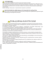
BRANCHEMENTS ÉLECTRIQUES
Pour garantir la sécurité de l’opérateur et prévenir tout risque d’endommagement des composants,
la centrale doit impérativement être débranchée de l’alimentation électrique pendant les opérations
de connexion et d’installation de la carte radio.
Pour les câbles d’alimentation, lignes moteurs, ligne clignotants/éclairage de courtoisie, serrure
électrique, utiliser un câble ayant une section adéquate à la longueur du parcours (1,5 mm2 mini-
mum).
Pour les alimentations auxiliaires, les commandes et les contacts de sécurité, le câble doit avoir
une section minimale de 0,5 mm2. Lorsque les câbles de commande sont très longs (plus de 30
m), un découplage par relais dans la centrale même est recommandé.
Si un fusible saute, le remplacer par un fusible ayant les mêmes caractéristiques après avoir éli-
miner la cause du court-circuit. Monter les différents dispositifs de sécurité, les butées de n de
course, les cellules photoélectriques, les barres palpeuses, le bouton d’arrêt.
Si un ou plusieurs dispositifs de sécurité ne sont pas installés, court-circuiter les bornes y affé-
rentes en utilisant la commande habituelle.
Tous les contacts N.F. associés à une même entrée doivent être reliés en série.
Tous les contacts N.O. associés à une même entrée doivent être reliés en parallèle.
Prévoir la pose d’éléments de déconnexion sur le réseau d’alimentation électrique directement
accessible sur place.
L’alimentation de la centrale prévoit la pose d’un SECTIONNEUR externe indépendant (non four-
ni), dimensionné comme il se doit.

19
FRANÇAIS
MODÈLES ET CARACTÉRISTIQUES
900CT-101 Centrale de commande pour 1 moteur 230 Vac pour portail coulissant ou basculant,
prédisposition pour carte radio
CARACTÉRISTIQUES TECHNIQUES CT-101
ALIMENTATION 230Vac/50Hz
PUISSANCE MAX. MOTEUR 1200 W
SORTIE ALIMENTATION AUXILIAIRES 24Vac 400mA
DURÉE MOUVEMENT 0-120sec
DURÉE PAUSE 0-120sec
TEMPÉRATURE DE FONCTIONNEMENT -20°C/+70°C
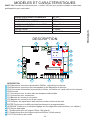
DESCRIPTION
DESCRIPTION
CN1 Barrette de connexion alimentation 230Vac, clignotante et veilleuse
CN2 Barrette de connexion des commandes et des dispositifs de sécurité
CN3 Connexion alimentation des auxiliaires 24Vac, en fonction du canal radio et de l’antenne
CN4 Encoder
JP1 Connecteur pour la carte radio du récepteur embrochable
JP3 Connecteur pour condenseur
JP4 Barrette de connexion du moteur
JP5 Barrette de connexion du n de course
LCD Afcheur de signalisation des fonctions et des entrées de sécurité
ENTER Touche pour le délement des fonctions pour la programmation
UP/DOWN Touche pour la variation/réglage de la conguration des fonctions ( voir tableau )
P/P Bouton pas-à-pas
F1 Fusible protection de la ligne 230Vac 10A retardé
F2 Fusible protection de la ligne auxiliaires 230Vac 315mA retardé
FCC FCA Led du n de course
1 2 3 4 5
9
2
8
7
1
13
14
6
3
4
--
. .
6 7 8 9 10 11 12 13 14 15 16 17 18
22 23 24
21
20
19
25 26 27
5
12
11
10
15
14
13
12
11
10
9
8
7
6
5
4
3
2
1
15

20
FRANÇAIS
RG58
230Vac
1 2 3 4 5 6 7 8 9 10 11 12 13 14 15 16 17 18
CN1
Destiné à la connexion des alimentations de la carte
1) N 230Vac
2) F 230Vac
3) L.C. Relié à la lumière de courtoisie max.25W 230Vac
4) COM LC/LP Commun à la lumière de courtoisie ou à la lampe clignotante
5) LMP Relié à la lampe clignotante max.25W 230Vac
CN2
6) $ Sert à relier l’installation à la terre
7) PED Fonction Passage piéton
Reliée entre la borne N°7 et la borne N° 12 Contact N.O. Normalement ouvert
8) P/P Fonctionnement Pas-à-Pas
CConnecté entre la borne N° 8 et la borne N°12 Contact N.O. Normalement ouvert
Entrée de commande Ouvrir/Fermer ou Ouvrir/Stop/Fermer en fonction de la sélection du paramètre D
9) F1 Fonction Photocellule Close
Raccordée entre la borne N° 9 et la borne N° 12 Contact N.F. Normalement fermé
Cette entrée est considérée comme une sécurité, le contact peut être coupé à tout moment pendant la fermeture
de l’automatisme, ce qui entraîne le blocage instantané du mouvement et inverse le sens de marche.
10) F2 Fonction Photocellule Open
Connectée entre la borne N° 10 et la borne N° 12 Contact N.F. Normalement fermé
Cette entrée est considérée comme une sécurité, le contact peut être coupé à tout moment pendant l’ouverture de
l’automatisme, ce qui entraîne le blocage instantané du mouvement, l’automatisme continuera l’ouverture dès que
le contact sera rétabli
11) STP Fonctionnement Stop
Connecté entre la borne N° 11 et la borne N° 12 Contact normalement fermé N.F. Cette entrée est considérée
comme une sécurité, le contact peut être coupé à tout moment ce qui entraîne le blocage instantané de l’automa-
tisme en désactivant toute fonction, y compris la fermeture automatique
12) COM
NA PED
NA P/P
NC STOP
COMUNE
Antenna
Alim. accessori
1 2 3 4 5 6 7 8 9 10 11 12 13 14 15 16 17 18
3
TX RX
34
NC
F1
3
TX RX
34
NC
F2
1212
1212
24Vac/dc
- +
24Vac/dc
- +
24Vac/dc
- +
24Vac/dc
- +
La pagina si sta caricando...
La pagina si sta caricando...
La pagina si sta caricando...
La pagina si sta caricando...
La pagina si sta caricando...
La pagina si sta caricando...
La pagina si sta caricando...
La pagina si sta caricando...
La pagina si sta caricando...
La pagina si sta caricando...
La pagina si sta caricando...
La pagina si sta caricando...
La pagina si sta caricando...
La pagina si sta caricando...
La pagina si sta caricando...
La pagina si sta caricando...
La pagina si sta caricando...
La pagina si sta caricando...
La pagina si sta caricando...
La pagina si sta caricando...
La pagina si sta caricando...
La pagina si sta caricando...
La pagina si sta caricando...
La pagina si sta caricando...
La pagina si sta caricando...
La pagina si sta caricando...
La pagina si sta caricando...
La pagina si sta caricando...
La pagina si sta caricando...
La pagina si sta caricando...
La pagina si sta caricando...
La pagina si sta caricando...
La pagina si sta caricando...
La pagina si sta caricando...
La pagina si sta caricando...
La pagina si sta caricando...
La pagina si sta caricando...
La pagina si sta caricando...
La pagina si sta caricando...
La pagina si sta caricando...
La pagina si sta caricando...
La pagina si sta caricando...
La pagina si sta caricando...
La pagina si sta caricando...
La pagina si sta caricando...
La pagina si sta caricando...
La pagina si sta caricando...
La pagina si sta caricando...
-
 1
1
-
 2
2
-
 3
3
-
 4
4
-
 5
5
-
 6
6
-
 7
7
-
 8
8
-
 9
9
-
 10
10
-
 11
11
-
 12
12
-
 13
13
-
 14
14
-
 15
15
-
 16
16
-
 17
17
-
 18
18
-
 19
19
-
 20
20
-
 21
21
-
 22
22
-
 23
23
-
 24
24
-
 25
25
-
 26
26
-
 27
27
-
 28
28
-
 29
29
-
 30
30
-
 31
31
-
 32
32
-
 33
33
-
 34
34
-
 35
35
-
 36
36
-
 37
37
-
 38
38
-
 39
39
-
 40
40
-
 41
41
-
 42
42
-
 43
43
-
 44
44
-
 45
45
-
 46
46
-
 47
47
-
 48
48
-
 49
49
-
 50
50
-
 51
51
-
 52
52
-
 53
53
-
 54
54
-
 55
55
-
 56
56
-
 57
57
-
 58
58
-
 59
59
-
 60
60
-
 61
61
-
 62
62
-
 63
63
-
 64
64
-
 65
65
-
 66
66
-
 67
67
-
 68
68


Key Automation 580ISCT-101 Manuale utente
- Tipo
- Manuale utente
in altre lingue
- français: Key Automation 580ISCT-101 Manuel utilisateur
- español: Key Automation 580ISCT-101 Manual de usuario
- Deutsch: Key Automation 580ISCT-101 Benutzerhandbuch
- Nederlands: Key Automation 580ISCT-101 Handleiding
- português: Key Automation 580ISCT-101 Manual do usuário
- polski: Key Automation 580ISCT-101 Instrukcja obsługi
Documenti correlati

Altri documenti
-
Genius SPRINT 03 04 Istruzioni per l'uso
-
-
BFT Rigel5 Manuale del proprietario
-
-
Genius BRAIN03 BRAIN04 Istruzioni per l'uso
-
-
 GiBiDi SC230E Manuale del proprietario
-
Telcoma T101 Manuale del proprietario
-
