
B000882
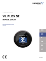
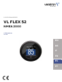
VL FLEX 52MM SERIES
VL FLEX 52
NMEA 2000
USER MANUAL
rev. AB
EN
DE
IT
FR
ES
PT

B000882
LANGUAGE PAGE
ENGLISH 3
DEUTSCH 26
ITALIANO 50
FRANÇAIS 74
ESPAÑOL 98

B000882
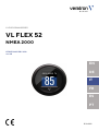
VL FLEX 52MM SERIES
VL FLEX 52
NMEA 2000
USER MANUAL
rev. AB
EN
DE
IT
FR
ES
PT

CONTENT
B000882
CONTENT
Content ............................................................................................ 2
Introduction .................................................................................... 3
Package Contents ..................................................................................... 3
The all-in-one Device ............................................................................... 3
Contactless Configuration .................................................................... 3
Safety Information ......................................................................... 4
Safety During Installation ....................................................................... 4
Safety After Installation ........................................................................... 5
Electrical Connection .............................................................................. 5
Installation ...................................................................................... 6
Before the Assembly ................................................................................ 6
Mounting with Spinlock Nut .................................................................. 7
Flush Mounting ........................................................................................... 8
Connections .................................................................................... 9
Pinout .............................................................................................................. 9
Wiring Harness ............................................................................................ 9
NMEA 2000® Pinout ........................................................................... 10
Connection to the NMEA 2000® Network ............................... 10
Frequency Input Connection............................................................... 11
Resistance Sensor Connection ........................................................... 11
Configuration ............................................................................... 12
VL Fex Configurator App ...................................................................... 12
Configure Device ...................................................................................... 12
Supported Configurations ................................................................... 16
Display Layout .............................................................................. 18
Single Layout .............................................................................................. 18
Dual Layout ................................................................................................. 18
ALARM DISPLAY ..................................................................................... 19
Technical Data ............................................................................. 20
Datasheet.................................................................................................... 20
Supported NMEA 2000® PGNs ...................................................... 21
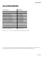
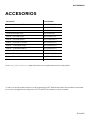
Accessories .................................................................................. 22

INTRODUCTION
B000882
INTRODUCTION
PACKAGE CONTENTS
Item number
Description
B00043501
1x VL Flex 52
A2C5205947101
1x 52 mm spinlock nut
A2C9582260001
1x wiring harness
B000100
1x safety instructions
THE ALL-IN-ONE DEVICE
The VL Flex 52 can be easily configured as the display device you need thanks to its 1.44" TFT display,
readable even in strong sunlight, embedded in a standard 52 mm diameter housing.
Supported analog inputs allow direct reading from motor sensors, and the NMEA 2000® interface extends
this function by allowing the VL Flex to read from the digital network.
The simple but effective display layout can be set up in a single or dual layout, presenting the data in a clear
and intuitive way, while the colored bar graph and alarm display allow you to interpret the data more quickly.
CONTACTLESS CONFIGURATION
Thanks to contactless configuration, you can configure your all-in-one instrument with a simple "tap"!
Start the smartphone app and define your settings via the user-friendly interface. Then simply hold your
smartphone on the front lens of the VL Flex to transfer the configuration immediately.
Thanks to the built-in passive antenna, the configuration can be done without power supply!

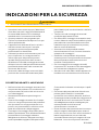
SAFETY INFORMATION
B000882
SAFETY INFORMATION
WARNING
• No smoking! No open fire or heat sources!
• The product was developed, manufactured
and inspected according to the basic safety
requirements of EC Guidelines and state-of-
the-art technology.
• The instrument is designed for use in grounded
vehicles and machines as well as in pleasure
boats, including non-classified commercial
shipping.
• Use our product only as intended. Use of the
product for reasons other than its intended use
may lead to personal injury, property damage
or environmental damage. Before installation,
check the vehicle documentation for vehicle
type and any possible special features!
• Use the assembly plan to learn the location of
the fuel/hydraulic/compressed air and
electrical lines!
• Note possible modifications to the vehicle,
which must be considered during installation!
• To prevent personal injury, property damage or
environmental damage, basic knowledge of
motor vehicle/shipbuilding electronics and
mechanics is required.
• Make sure that the engine cannot start
unintentionally during installation!
• Modifications or manipulations to veratron
products can affect safety. Consequently, you
may not modify or manipulate the product!
• When removing/installing seats, covers, etc.,
ensure that lines are not damaged and plug-in
connections are not loosened!
• Note all data from other installed instruments
with volatile electronic memories.
SAFETY DURING INSTALLATION
• During installation, ensure that the product’s
components do not affect or limit vehicle
functions. Avoid damaging these components!
• Only install undamaged parts in a vehicle!
• During installation, ensure that the product
does not impair the field of vision and that it
cannot impact the driver’s or passenger’s head!
• A specialized technician should install the
product. If you install the product yourself,
wear appropriate work clothing. Do not wear
loose clothing, as it may get caught in moving
parts. Protect long hair with a hair net.
• When working on the on-board electronics, do
not wear metallic or conductive jewelry such as
necklaces, bracelets, rings, etc.
• If work on a running engine is required, exercise
extreme caution. Wear only appropriate work
clothing as you are at risk of personal injury,
resulting from being crushed or burned.
• Before beginning, disconnect the negative
terminal on the battery, otherwise you risk a
short circuit. If the vehicle is supplied by
auxiliary batteries, you must also disconnect
the negative terminals on these batteries!
Short circuits can cause fires, battery
explosions and damages to other electronic
systems. Please note that when you disconnect
the battery, all volatile electronic memories
lose their input values and must be
reprogrammed.
• If working on gasoline boat motors, let the
motor compartment fan run before beginning
work.
• Pay attention to how lines and cable harnesses
are laid so that you do not drill or saw through
them!
• Do not install the product in the mechanical
and electrical airbag area!

SAFETY INFORMATION
B000882
• Do not drill holes or ports in load-bearing or
stabilizing stays or tie bars!
• When working underneath the vehicle, secure
it according to the specifications from the
vehicle manufacturer.
• Note the necessary clearance behind the drill
hole or port at the installation location.
Required mounting depth: 65 mm.
• Drill small ports; enlarge and complete them, if
necessary, using taper milling tools, saber saws,
keyhole saws or files. Deburr edges. Follow the
safety instructions of the tool manufacturer.
• Use only insulated tools, if work is necessary on
live parts.
• Use only the multimeter or diode test lamps
provided, to measure voltages and currents in
the vehicle/machine or boat. Use of
conventional test lamps can cause damage to
control units or other electronic systems.
• The electrical indicator outputs and cables
connected to them must be protected from
direct contact and damage. The cables in use
must have enough insulation and electric
strength and the contact points must be safe
from touch.
• Use appropriate measures to also protect the
electrically conductive parts on the connected
consumer from direct contact. Laying metallic,
uninsulated cables and contacts is prohibited.
SAFETY AFTER INSTALLATION
• Connect the ground cable tightly to the
negative terminal of the battery.
• Reenter/reprogram the volatile electronic
memory values.
• Check all functions.
• Use only clean water to clean the components.
Note the Ingress Protection (IP) ratings (IEC
60529).
ELECTRICAL CONNECTION
• Note cable cross-sectional area!
• Reducing the cable cross-sectional area leads
to higher current density, which can cause the
cable cross-sectional area in question to heat
up!
• When installing electrical cables, use the
provided cable ducts and harnesses; however,
do not run cables parallel to ignition cables or
to cables that lead to large electricity
consumers.
• Fasten cables with cable ties or adhesive tape.
Do not run cables over moving parts. Do not
attach cables to the steering column!
• Ensure that cables are not subject to tensile,
compressive or shearing forces.
• If cables are run through drill holes, protect
them using rubber sleeves or the like.
• Use only one cable stripper to strip the cable.
Adjust the stripper so that stranded wires are
not damaged or separated.
• Use only a soft soldering process or
commercially available crimp connector to
solder new cable connections!
• Make crimp connections with cable crimping
pliers only. Follow the safety instructions of the
tool manufacturer.
• Insulate exposed stranded wires to prevent
short circuits.
• Caution: Risk of short circuit if junctions are
faulty or cables are damaged.
• Short circuits in the vehicle network can cause
fires, battery explosions and damages to other
electronic systems. Consequently, all power
supply cable connections must be provided
with weldable connectors and be sufficiently
insulated.
• Ensure ground connections are sound.
• Faulty connections can cause short circuits.
Only connect cables according to the electrical
wiring diagram.
•
If operating the instrument on power supply
units, note that the power supply unit must be
stabilized and it must comply with the following
standard: DIN EN 61000, Parts 6-1 to 6-4.

INSTALLATION
B000882
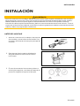
INSTALLATION
WARNING
Before beginning, disconnect the negative terminal on the battery, otherwise you risk a
short circuit.
If the vehicle is supplied by auxiliary batteries, you must also disconnect the negative terminals on these
batteries! Short circuits can cause fires, battery explosions and damages to other electronic systems.
Please note that when you disconnect the battery, all volatile electronic memories lose their input values
and must be reprogrammed.
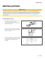
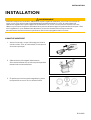
BEFORE THE ASSEMBLY
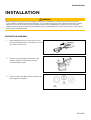
1.
Before beginning, turn off the ignition and
remove the ignition key. If necessary, remove
the main circuit switch
2. Disconnect the negative terminal on the
battery. Make sure the battery cannot
unintentionally restart.
3. Place the device at least 300 mm away from
any magnetic compass.

INSTALLATION
B000882
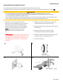
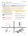
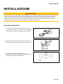
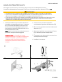
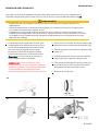
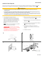
MOUNTING WITH SPINLOCK NUT
Conventional mounting. (Device is inserted into the hole from the front).
The panel thickness can be in the range of 0.5 to 20 mm. The hole must have a diameter of 53 mm [B].
WARNING
• Do not drill holes and installation openings in load-bearing or stabilizing struts or spars!
• For the installation location, ensure the necessary clearance behind the holes or the installation
opening. Required installation depth 65 mm.
• Pre-drill small installation openings, enlarge with cone cutter, hole saw, jigsaw or file if necessary and
finish. Deburr edges. Refer to the safety instructions of the hand tool manufacturer.
1. Different covers can be mounted as an
alternative to the supplied cover. In this case,
carefully remove it with a screwdriver [A],
attach the new bezel to the instrument and
press it until it is flush with the cover glass.
Note: When removing, the front ring
damaged and can no longer be used
be
IMPORTANT: If you install a chrome bezel, you
must set up the device before installation. The
metal particles contained in the chrome trim
may affect the performance of the wireless
interface!
2. Make a round hole, taking into account the
external dimensions of the device. [B]
3. Remove the spinlock nut and insert the device
frontally. [C]
4. Align the spinlock nut as shown in [D],
according to the thickness of the plate.
5. Feed the cables through the spinlock nut and
carefully screw it in at least two turns.
6. Connect the plugs.
A B
C
D

INSTALLATION
B000882
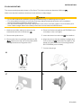
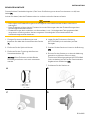
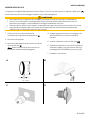
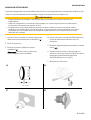
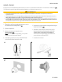
FLUSH MOUNTING
The recommended panel thickness is 1.5 to 3mm. The hole must have a diameter of 48.1mm [A].
Make sure that the installation location is level and has no sharp edges.
WARNING
• Do not drill holes and installation openings in load-bearing or stabilizing struts or spars!
• For the installation location, ensure the necessary clearance behind the holes or the installation
opening. Required installation depth 65 mm.
• Pre-drill small installation openings, enlarge with cone cutter, hole saw, jigsaw or file if necessary and
finish. Deburr edges. Refer to the safety instructions of the hand tool manufacturer.
1. Make a round hole, taking into account the
external dimensions of the device. [A]
2. Remove the spinlock nut
3. Remove the front ring using a screwdriver. [B]
Note: When removing, the orifice plate will be
damaged and can no longer be used.
4. Place the flushmount gasket A2C53215640 (not
included) on the cover glass.
5. Insert the device into the hole [C] from behind.
6. Align the unit so that the reading is straight and
fix it to the studs [D] attached to the back of the
panel using the flushmount mounting bracket
A2C59510864 (not included).
7. Connect the plugs.
A
B
C
D

CONNECTIONS
B000882
CONNECTIONS
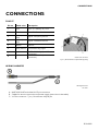
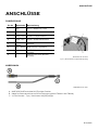
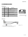
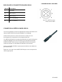
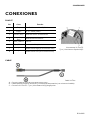
PINOUT
Pin no. Cable color
Description
1 Red Term. 15 - Battery 12 / 24 V
2 Black Term. 31 - Ground
3
Green
/
Red Signal - frequency sensor
4
Yellow
/
Red Signal - resistance sensor
5
Blue /
White LIN bus
6 Red / White
Illumination day/night
7 -
NMEA 2000
High
(
on M12
connector)
8 -
NMEA
2000
Low
(
on M12
connector)
Rear view VL Flex
Tyco / Hirschmann 8-poles MQS plug
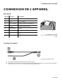
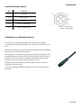
WIRING HARNESS
Wiring harness
VL Flex
A: NMEA 2000® DeviceNet M12 5-pin connector
B: Cables for sensor connection and power supply (see colors in the table)
C: VL Flex connector - Tyco / Hirschmann MQS 8-pin

CONNECTIONS
B000882
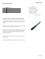
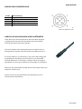
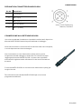
NMEA 2000® PINOUT
Micro-C M12 5-pin connector
Male, Cable View
Pin no.
Description
1
Shielding
2
NET
-
S (V+)
3
NET
-
C (V
-
)
4
NET
-
H
(CAN H)
5
NET
-
L (CAN L)
CONNECTION TO THE NMEA 2000® NETWORK
Once mounting is complete, the device can be connected to
the NMEA 2000® network via the designated socket on the
cabling.
Make sure to screw the plug all the way on. This is the only way
to guarantee that the connection is waterproof.
A drop cable is only required if the total length of the supplied
cabling is not sufficient to reach the NMEA 2000® backbone.
In this case it is possible to extend the cable with one of the
additional drop cables.
Note that NMEA 2000® does not allow drop cables longer
than 6 meters.
Stick to the NMEA 2000® standard for proper network setup.

CONNECTIONS
B000882
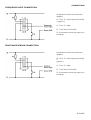
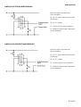
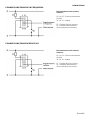
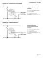
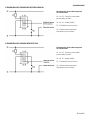
FREQUENCY INPUT CONNECTION
Designations within the connection
diagram:
15 - Term. 15 - switched positive 12/24
V (ignition)
31 - Term. 31 - Mass
F1 - Fuse 3A (not included)
S1 - Illumination switch day/night (not
included)
RESISTANCE SENSOR CONNECTION
Designations within the connection
diagram:
15 - Term. 15 - switched positive 12/24
V
(Ignition)
31 - Term. 31 - Mass
F1 - Fuse 3A (not included)
S1 - Illumination switch day/night (not
included)

CONFIGURATION
B000882
CONFIGURATION
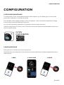
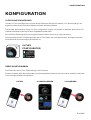
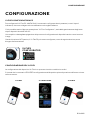
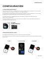
VL FEX CONFIGURATOR APP
To configure the VL Flex, some parameters have to be configured, e.g. the display type, the connected
sensor and its calibration or the alarm threshold.
This is possible via the smartphone app "VL Flex Configurator", which can be downloaded free of charge
from the stores for both Android and iOS devices.
You can also find a simple explanation of the setup process as in-app instructions.
Thanks to the passive NFC receiver, the VL Flex device can be configured as described below without the
need for a power supply.
VL FLEX
CONFIGURATOR
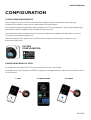
CONFIGURE DEVICE
Setting up the VL Flex device is a three-step process.
Remember that the configuration of the instrument must be read before it can be changed and written to
the instrument.
1.
READ
2.
CONFIGURE
3.
WRITE

CONFIGURATION
B000882
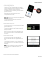
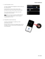
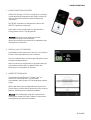
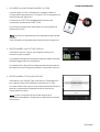
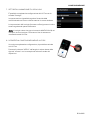
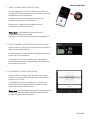
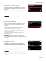
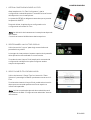
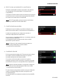
1.
READ CONFIGURATION
Open the "VL Flex Configurator" app and read the
current configuration of the device by "touching" the
front lens of the device with the smartphone.
The READ operation is mandatory before the WRITE
operation is allowed.
After reading, the app is set with the current
configuration of the VL Flex.
Note: The position of the antenna on the smartphone
depends on the model.
For more information, refer to the smartphone
manufacturer's manual.
2.
SELECT DISPLAY LAYOUT
Use the Layout section to choose between single and
double image layouts.
The preview image at the top of the app screen will
update accordingly.
When Dual Layout is selected, the app expands the
device settings to be able to configure both fields of
the screen.
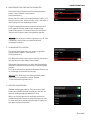
3.
SELECT DISPLAY TYPE
Use the Gauge Type item in the Data Selection
section to select the data to be displayed on the VL
Flex.
If the dual layout is selected, you can select the data
for the upper as well as for the lower part of the screen
separately.
Note: For the complete list of supported data types,
see the Supported Configurations table in this
document.
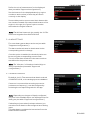
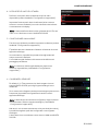
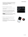
4.
SELECT MASS UNITS AND INSTANCE

CONFIGURATION
B000882
Define the
unit of measurement for the
displayed
data. (see table "Supported configurations").
Set the instance for the displayed data (e.g. engine
number or tank number) so that they are shown
correctly on the display.
Some rudder position sensors send their data on their
own instance instead of the associated instance of the
engine. In this case, the "Ignore" option must be
selected as the Engine Instance.
Note: The defined instance is also used by the VL Flex
when receiving data from NMEA 2000®.
5.
ALARM SETTINGS
For some data types an alarm can be set (see table
"Supported configurations").
The alarm can be activated or deactivated via the
corresponding switch in the app.
Once the option is enabled, the threshold value can
be set using the corresponding numeric field.
The unit of the alarm threshold is the same unit that
was defined in the previous step.
Note: The "direction" of the alarm threshold (up or
down) is predefined (see table "Supported
configurations").
6.
CALIBRATE SENSOR
By default, the VL Flex assumes that data is received
via NMEA 2000® , so the analog inputs are disabled.
If a sensor is connected via an analog connection
(resistance or frequency), it can be configured by
activating the corresponding switch in the app.
Note: Depending on the type of display configured,
only one of the available inputs can be assigned to the
data type. (see table "Supported configurations")
If a dual layout (two values) has been selected, you
can select which data is to be configured as an analog
input.
The other data is considered to be received from the
NMEA 2000® network.

CONFIGURATION
B000882
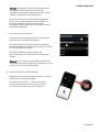
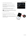
7.
LIGHTING AND CLOCK
You can complete the configuration of the VL Flex via
the "Settings" tab.
In this section you can set the intensity of the
backlight during the day and night using the slider.
This screen can also be used to adjust the clock
settings (format and offset).
Note: The clock is only received via NMEA 2000®
from an external GPS receiver. It is not counted
internally by the VL Flex.
8. TRANSFER CONFIGURATION
Once the configuration is complete, you can
download it to VL Flex.
Press the "APPLY" button in the upper right corner of
the app and "touch" the front lens of the device with
your smartphone.

CONFIGURATION
B000882
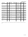
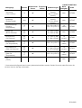
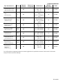
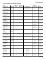
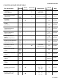
SUPPORTED CONFIGURATIONS
Display type Unit Resistance
Sensor
Frequency
Sensor Calibrations Alarm
available
PGN
Tachometer rpm - ✔ Pulses per
revolution No 127488
Boat speed
kn
km/h
mph
- ✔ Pulses per unit No 128259
Ammeter
A - - - No 127508
Voltmeter
V - - Measures supply
voltage No 127508
Battery charge % - - - Yes
(below) 127506
Battery status
% - - - Yes
(below) 127506
Battery temperature
°C
°F - - - Yes
(above) 127508
Battery autonomy
h
days - - - No 127506
Operating hours
h - ✔ Calculated
internally No 127489
Speed Over Ground
kn
km/h
mph
- - - No 129026
Course Over Ground
deg - - - No 129026
Depth
m
ft - - - Yes
(below) 128267
Fuel level
% ✔ -
0
-
90
Ω
3 - 180 Ω
240 - 33 Ω
90 - 4 Ω
105 - 4 Ω
Yes
(below) 127505
Fresh water level
% ✔ -
3 - 180 Ω
240 - 33 Ω
90 - 4 Ω
No 127505
Waste water level
% ✔ -
3 - 180 Ω
240 - 33 Ω
90 - 4 Ω
No 127505

CONFIGURATION
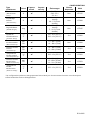
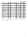
B000882
Display type Unit Resistance
Sensor
Frequency
Sensor Calibrations Alarm
available
PGN
Trim % ✔ -
167
-
10
Ω
(
Single
Station)
84 - 5 Ω (Dual
Station)
No 127488
Rudder position deg ✔ -
10
-
180
Ω
(
Single
Station)
5 - 90 Ω (Dual
Station)
No 127245
Cooling water temp. °C
°F ✔ -
291 - 22 Ω (120 °C)
322 - 19 Ω
(150 °C)
Yes
(above) 127489
Boost pressure bar
PSI ✔ - 10 - 184 Ω (2 bar)
10 - 184 Ω (5 bar) No 127488
Engine oil pressure bar
PSI ✔ - 10 - 184 Ω (5 bar)
10 - 184 Ω (10 bar)
Yes
(below) 127489
Engine oil temp. °C
°F ✔ - 322 - 19 Ω
(150 °C)
Yes
(above) 127489
Transmission oil
pressure
bar
PSI ✔ -
10 - 184 Ω (10 bar)
10 - 184 Ω (25 bar)
10 - 211 Ω (30 bar)
Yes
(below) 127493
Transmission oil
temp.
°C
°F ✔ - 322 - 19 Ω
(150 °C)
Yes
(above) 127493
Clock
- - - - No 126992
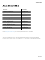
* Supported configurations can be updated at any time. Make sure you always use the latest version of the
app.

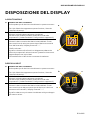
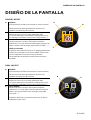
DISPLAY LAYOUT
B000882
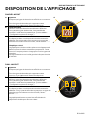
DISPLAY LAYOUT
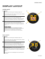
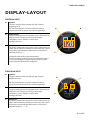
SINGLE LAYOUT
A.
Symbol
Indicates, which data type is displayed right now.
For the data types, which support this function, there is
also the instance indicated here.
B.
Unit
Shows the unit of the currently displayed data.
For some data types it’s possible to change the unit in
the settings. (See table “Supported Configurations”)
C.
Measured
value
This shows the numeric value of the dedicated
measured data. If there aren’t any values received for
this data type or they are out of range, the display will
show “---“.
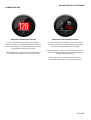
Coloured Graph
The coloured graphic in the background is a bar
diagram that puts the measured value in perspective.
This function isn’t supported for all data types.
The white lines on the left side show the scalation.
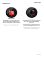
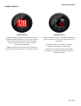
DUAL LAYOUT
A.
Symbol
Indicates, which data type is displayed right now.
For the data types, which support this function, there is
also the instance indicated here.
B.
Unit
Shows the unit of the currently displayed data.
For some data types it’s possible to change the unit in
the settings. (See table “Supported Configurations”)
C.
Measured Value
This shows the numeric value of the dedicated
measured data. If there aren’t any data received for this
data type or the values are out of range, the display will
show “---“.
The bar graph can’t be displayed in the dual layout for
any value.
A
B
C
B
C
A
La pagina si sta caricando...
La pagina si sta caricando...
La pagina si sta caricando...
La pagina si sta caricando...
La pagina si sta caricando...
La pagina si sta caricando...
La pagina si sta caricando...
La pagina si sta caricando...
La pagina si sta caricando...
La pagina si sta caricando...
La pagina si sta caricando...
La pagina si sta caricando...
La pagina si sta caricando...
La pagina si sta caricando...
La pagina si sta caricando...
La pagina si sta caricando...
La pagina si sta caricando...
La pagina si sta caricando...
La pagina si sta caricando...
La pagina si sta caricando...
La pagina si sta caricando...
La pagina si sta caricando...
La pagina si sta caricando...
La pagina si sta caricando...
La pagina si sta caricando...
La pagina si sta caricando...
La pagina si sta caricando...
La pagina si sta caricando...
La pagina si sta caricando...
La pagina si sta caricando...
La pagina si sta caricando...
La pagina si sta caricando...
La pagina si sta caricando...
La pagina si sta caricando...
La pagina si sta caricando...
La pagina si sta caricando...
La pagina si sta caricando...
La pagina si sta caricando...
La pagina si sta caricando...
La pagina si sta caricando...
La pagina si sta caricando...
La pagina si sta caricando...
La pagina si sta caricando...
La pagina si sta caricando...
La pagina si sta caricando...
La pagina si sta caricando...
La pagina si sta caricando...
La pagina si sta caricando...
La pagina si sta caricando...
La pagina si sta caricando...
La pagina si sta caricando...
La pagina si sta caricando...
La pagina si sta caricando...
La pagina si sta caricando...
La pagina si sta caricando...
La pagina si sta caricando...
La pagina si sta caricando...
La pagina si sta caricando...
La pagina si sta caricando...
La pagina si sta caricando...
La pagina si sta caricando...
La pagina si sta caricando...
La pagina si sta caricando...
La pagina si sta caricando...
La pagina si sta caricando...
La pagina si sta caricando...
La pagina si sta caricando...
La pagina si sta caricando...
La pagina si sta caricando...
La pagina si sta caricando...
La pagina si sta caricando...
La pagina si sta caricando...
La pagina si sta caricando...
La pagina si sta caricando...
La pagina si sta caricando...
La pagina si sta caricando...
La pagina si sta caricando...
La pagina si sta caricando...
La pagina si sta caricando...
La pagina si sta caricando...
La pagina si sta caricando...
La pagina si sta caricando...
La pagina si sta caricando...
La pagina si sta caricando...
La pagina si sta caricando...
La pagina si sta caricando...
La pagina si sta caricando...
La pagina si sta caricando...
La pagina si sta caricando...
La pagina si sta caricando...
La pagina si sta caricando...
La pagina si sta caricando...
La pagina si sta caricando...
La pagina si sta caricando...
La pagina si sta caricando...
La pagina si sta caricando...
La pagina si sta caricando...
La pagina si sta caricando...
La pagina si sta caricando...
La pagina si sta caricando...
La pagina si sta caricando...
-
 1
1
-
 2
2
-
 3
3
-
 4
4
-
 5
5
-
 6
6
-
 7
7
-
 8
8
-
 9
9
-
 10
10
-
 11
11
-
 12
12
-
 13
13
-
 14
14
-
 15
15
-
 16
16
-
 17
17
-
 18
18
-
 19
19
-
 20
20
-
 21
21
-
 22
22
-
 23
23
-
 24
24
-
 25
25
-
 26
26
-
 27
27
-
 28
28
-
 29
29
-
 30
30
-
 31
31
-
 32
32
-
 33
33
-
 34
34
-
 35
35
-
 36
36
-
 37
37
-
 38
38
-
 39
39
-
 40
40
-
 41
41
-
 42
42
-
 43
43
-
 44
44
-
 45
45
-
 46
46
-
 47
47
-
 48
48
-
 49
49
-
 50
50
-
 51
51
-
 52
52
-
 53
53
-
 54
54
-
 55
55
-
 56
56
-
 57
57
-
 58
58
-
 59
59
-
 60
60
-
 61
61
-
 62
62
-
 63
63
-
 64
64
-
 65
65
-
 66
66
-
 67
67
-
 68
68
-
 69
69
-
 70
70
-
 71
71
-
 72
72
-
 73
73
-
 74
74
-
 75
75
-
 76
76
-
 77
77
-
 78
78
-
 79
79
-
 80
80
-
 81
81
-
 82
82
-
 83
83
-
 84
84
-
 85
85
-
 86
86
-
 87
87
-
 88
88
-
 89
89
-
 90
90
-
 91
91
-
 92
92
-
 93
93
-
 94
94
-
 95
95
-
 96
96
-
 97
97
-
 98
98
-
 99
99
-
 100
100
-
 101
101
-
 102
102
-
 103
103
-
 104
104
-
 105
105
-
 106
106
-
 107
107
-
 108
108
-
 109
109
-
 110
110
-
 111
111
-
 112
112
-
 113
113
-
 114
114
-
 115
115
-
 116
116
-
 117
117
-
 118
118
-
 119
119
-
 120
120
-
 121
121


in altre lingue
- français: veratron B00043501 Manuel utilisateur
- español: veratron B00043501 Manual de usuario
- Deutsch: veratron B00043501 Benutzerhandbuch
Documenti correlati
Altri documenti
-
Garmin GPSMAP® 1222 Touch Guida d'installazione
-
Garmin GPSMAP 7600 series Manuale del proprietario
-
Torqeedo Display Gateway / Twin TQ-CAN Istruzioni per l'uso
-
Garmin GHP Reactor™ Hydraulic Autopilot Guida d'installazione
-
Simrad NSO evo3S Guida d'installazione
-
Garmin GPSMAP® 1222xsv Touch Guida d'installazione
-
-
Garmin GPSMAP 1242 Touch Manuale del proprietario
-
 PIETRO FIORENTINI Mod. FEX Manuale del proprietario
