veratron Professional Rudder Angle Indicator Manuale utente
- Tipo
- Manuale utente

B000856
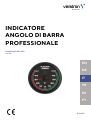
PROFESSIONAL RUDDER
ANGLE INDICATOR
OPERATING INSTRUCTIONS
rev. AB
EN
DE
IT
FR
ES
PT

B000856
LANGUAGE PAGE
ENGLISH 3
DEUTSCH 18
ITALIANO 34
FRANÇAIS 50

B000856
PROFESSIONAL RUDDER
ANGLE INDICATOR
OPERATING INSTRUCTIONS
rev. AB
EN
DE
IT
FR
ES
PT

CONTENT
B000856
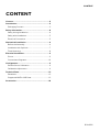
CONTENT
Content ............................................................................... 2
Introduction ....................................................................... 3
Packaging Content .................................................................... 3
Safety Information ............................................................ 4
Safety during Installation ......................................................... 4
Safety after Installation .............................................................5
Electrical Connection ...............................................................5
Mechanical Installation ................................................... 6
Before the Assembly ................................................................. 6
Installation with Spinlock ......................................................... 7
Flush Mounting ............................................................................ 8
Electrical Installation ....................................................... 9
Pinout ............................................................................................... 9
Connections Diagrams ...........................................................10
Configuration ................................................................... 11
Default Sensor Calibration .................................................... 11
Calibration Adjustment ........................................................... 11
Technical Data ................................................................. 13
Datasheet...................................................................................... 13
Supported NMEA 0183 Data............................................... 13
Accessories ...................................................................... 14

INTRODUCTION
B000856
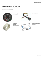
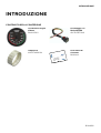
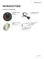
INTRODUCTION
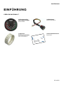
PACKAGING CONTENT
1x Rudder Angle
Indicator gauge
B00067401
1x Wire Harness
A2C1507870001
1x Mounting
Spinlock
A2C1376090001
1x Safety Instructions
B000100

SAFETY INFORMATION
B000856
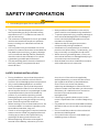
SAFETY INFORMATION
WARNING
• No smoking! No open fire or heat sources!
• The product was developed, manufactured
and inspected according to the basic safety
requirements of EC Guidelines and state-of-
the-art technology.
• The instrument is designed for use in grounded
vehicles and machines as well as in pleasure
boats, including non-classified commercial
shipping.
• Use our product only as intended. Use of the
product for reasons other than its intended use
may lead to personal injury, property damage
or environmental damage. Before installation,
check the vehicle documentation for vehicle
type and any possible special features!
• Use the assembly plan to learn the location of
the fuel/hydraulic/compressed air and
electrical lines!
• Note possible modifications to the vehicle,
which must be considered during installation!
• To prevent personal injury, property damage or
environmental damage, basic knowledge of
motor vehicle/shipbuilding electronics and
mechanics is required.
• Make sure that the engine cannot start
unintentionally during installation!
• Modifications or manipulations to veratron
products can affect safety. Consequently, you
may not modify or manipulate the product!
• When removing/installing seats, covers, etc.,
ensure that lines are not damaged and plug-in
connections are not loosened!
• Note all data from other installed instruments
with volatile electronic memories.
SAFETY DURING INSTALLATION
• During installation, ensure that the product’s
components do not affect or limit vehicle
functions. Avoid damaging these components!
• Only install undamaged parts in a vehicle!
• During installation, ensure that the product
does not impair the field of vision and that it
cannot impact the driver’s or passenger’s head!
• A specialized technician should install the
product. If you install the product yourself,
wear appropriate work clothing. Do not wear
loose clothing, as it may get caught in moving
parts. Protect long hair with a hair net.
• When working on the on-board electronics, do
not wear metallic or conductive jewellery such
as necklaces, bracelets, rings, etc.
• If work on a running engine is required, exercise
extreme caution. Wear only appropriate work
clothing as you are at risk of personal injury,
resulting from being crushed or burned.
• Before beginning, disconnect the negative
terminal on the battery, otherwise you risk a
short circuit. If the vehicle is supplied by
auxiliary batteries, you must also disconnect
the negative terminals on these batteries!
Short circuits can cause fires, battery
explosions and damages to other electronic
systems. Please note that when you disconnect
the battery, all volatile electronic memories
lose their input values and must be
reprogrammed.
• If working on gasoline boat motors, let the
motor compartment fan run before beginning
work.
• Pay attention to how lines and cable harnesses
are laid so that you do not drill or saw through
them!
• Do not install the product in the mechanical
and electrical airbag area!
• Do not drill holes or ports in load-bearing or
stabilizing stays or tie bars!

SAFETY INFORMATION
B000856
• When working underneath the vehicle, secure
it according to the specifications from the
vehicle manufacturer.
• Drill small ports; enlarge and complete them, if
necessary, using taper milling tools, sabre saws,
keyhole saws or files. Deburr edges. Follow the
safety instructions of the tool manufacturer.
• Use only insulated tools if work is necessary on
live parts.
• Use only the multimeter or diode test lamps
provided, to measure voltages and currents in
the vehicle/machine or boat. Use of
conventional test lamps can cause damage to
control units or other electronic systems.
• The electrical indicator outputs and cables
connected to them must be protected from
direct contact and damage. The cables in use
must have enough insulation and electric
strength and the contact points must be safe
from touch.
• Use appropriate measures to also protect the
electrically conductive parts on the connected
consumer from direct contact. Laying metallic,
uninsulated cables and contacts is prohibited.
SAFETY AFTER INSTALLATION
• Connect the ground cable tightly to the
negative terminal of the battery.
• Reenter/reprogram the volatile electronic
memory values.
• Check all functions.
• Use only clean water to clean the components.
Note the Ingress Protection (IP) ratings (IEC
60529).
ELECTRICAL CONNECTION
• Note cable cross-sectional area!
• Reducing the cable cross-sectional area leads
to higher current density, which can cause the
cable cross-sectional area in question to heat
up!
• When installing electrical cables, use the
provided cable ducts and harnesses; however,
do not run cables parallel to ignition cables or
to cables that lead to large electricity
consumers.
• Fasten cables with cable ties or adhesive tape.
Do not run cables over moving parts. Do not
attach cables to the steering column!
• Ensure that cables are not subject to tensile,
compressive or shearing forces.
• If cables are run through drill holes, protect
them using rubber sleeves or the like.
• Use only one cable stripper to strip the cable.
Adjust the stripper so that stranded wires are
not damaged or separated.
• Use only a soft soldering process or
commercially available crimp connector to
solder new cable connections!
• Make crimp connections with cable crimping
pliers only. Follow the safety instructions of the
tool manufacturer.
• Insulate exposed stranded wires to prevent
short circuits.
• Caution: Risk of short circuit if junctions are
faulty or cables are damaged.
• Short circuits in the vehicle network can cause
fires, battery explosions and damages to other
electronic systems. Consequently, all power
supply cable connections must be provided
with weldable connectors and be sufficiently
insulated.
• Ensure ground connections are sound.
• Faulty connections can cause short circuits.
Only connect cables according to the electrical
wiring diagram.
• If operating the instrument on power supply
units, note that the power supply unit must be
stabilized and it must comply with the following
standard: DIN EN 61000, Parts 6-1 to 6-4.

MECHANICAL INSTALLATION
B000856
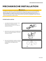
MECHANICAL INSTALLATION
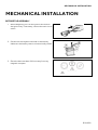
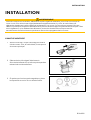
BEFORE THE ASSEMBLY
1.
Before beginning, turn off the ignition and remove
the ignition key. If necessary, remove the main circuit
switch
2. Disconnect the negative terminal on the battery.
Make sure the battery cannot unintentionally restart.
3. Place the device at least 300 mm away from any
magnetic compass.

MECHANICAL INSTALLATION
B000856
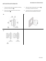
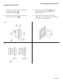
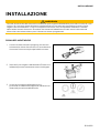
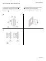
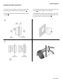
INSTALLATION WITH SPINLOCK
1. Create a circular hole in the panel considering
the device dimensions. [A]
2. Remove the spinlock and insert the device
from the front. [B]
3. Adjust the spinlock ad shown in picture [C]
according to the panel thickness
4. Carefully screw in the spinlock by hand at
least two turns and install the connector.
A B
C

MECHANICAL INSTALLATION
B000856
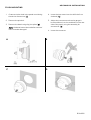
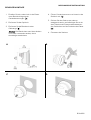
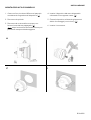
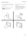
FLUSH MOUNTING
1. Create a circular hole in the panel considering
the device dimensions. [A]
2. Remove the spinlock.
3. Remove the bezel using slip joint pliers. [B]
Note: the bezel cannot be used after removal
since it can be damaged.
4. Insert the instrument into the drill hole from
the back. [C]
5. Adjust the instrument so that the gauge is
level and fasten it to the stud bolts on the rear
side of the panel, using the assembly kit
accessories. [D]
6. Insert the connector
A B
C
D

ELECTRICAL INSTALLATION
B000856
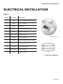
ELECTRICAL INSTALLATION
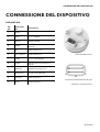
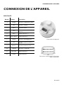
PINOUT
Pin No. Wire color Description
1 Red KL. 30 – Battery Power 12 / 24 V
2 Black KL. 31 – Ground
3 White Signal GND
4 Green 5 V output (Sensor feed)
5 Blue NMEA 0183 OUT +
6 Blue / White NMEA 0183 OUT -
7 Yellow KL. 15 – Ignition
8 Grey Resistive sensor input 0 – 400 Ω
9 Brown 0-5 V sensor input
10 Orange KL.58 – Illumination
11 Light Blue NMEA 0183 IN +
12 Purple NMEA 0183 IN -
Device rear view
Molex MX150 12-poles plug
Male, product side view

ELECTRICAL INSTALLATION
B000856
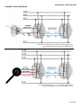
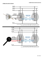
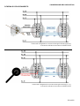
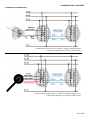
CONNECTIONS DIAGRAMS
Connections diagram for resistive rudder angle
sensor
and second gauge connected via NMEA 0183
Connections diagram for
0
–
5 V
rudder angle sensor
and second gauge connected via NMEA 0183

CONFIGURATION
B000856
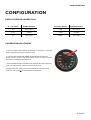
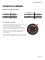
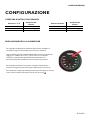
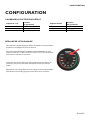
CONFIGURATION
DEFAULT SENSOR CALIBRATION
0 – 5 V Sensor Rudder Position Resistive Sensor Rudder Position
0 V 40° PORT 3 Ω 40° PORT
2.5 V Center 90 Ω Center
5 V 40° STBD 180 Ω 40° STBD
CALIBRATION ADJUSTMENT
In order to adjust the
default
calibration of the sensor, a
simple
three-steps procedure is implemented.
It is required to steer the rudder angle sensor to three key
positions (20° STBD, CENTER and 20° PORT) in order to store
the sensor reading at these points.
The embedded infrared pushbutton placed above the pointer
(see picture) must be used to confirm each step.
Simply near your finger to the infrared sensor area for more
than two seconds [A] to activate the pushbutton.

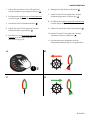
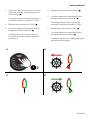
CONFIGURATION
B000856
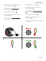
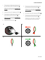
1. Keep pushing the infrared pushbutton (IR) to
start the calibration process. [A]
2. The illumination now blinks every 1 sec and
the pointer indicates 20° PORT
3. Move the rudder to 20° PORT. [B]
4. Keep “pushing” the IR button to store the
PORT reading. [A]
5. The illumination will blink twice every 1 sec
and the pointer indicates the center position
(0°).
6. Move the rudder to the center. [C]
7. Keep “pushing” the IR button to store the
CENTER reading. [A]
8. The illumination will blink three times every 1
sec and the pointer indicates the 20° STBD.
9. Move the rudder to 20° STBD. [D]
10. Keep “pushing” the IR button to store the
STBD reading. [A]
11. The gauge resets and the adjusted calibration
is now stored.
A B
C
D

TECHNICAL DATA
B000856
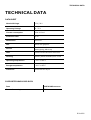
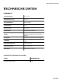
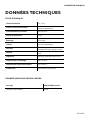
TECHNICAL DATA
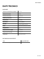
DATASHEET
Nominal Voltage 12 V / 24 V
Operating Voltage 8 – 32 V
Current consumption Max. 100 mA
Protection class IP X7
Illumination Red LED
Dial Black with graphics
Pointer Red illuminated, translucent
backlighting, black cap
Lens Plastic double lens anti-reflection
Housing Plastic (flame-retardant) acc. UL94
Operating temperature -30°C to 80°C
Storage temperature -40°C to 85°C
Connector Molex MX150 12 pin
SUPPORTED NMEA 0183 DATA
Data NMEA 0183 sentence
Rudder Sensor Angle $RSA

ACCESSORIES
B000856
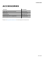
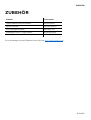
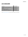
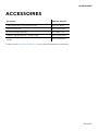
ACCESSORIES
Accessory Part Number
Pigtail cable with MX 150 connector A2C15078700
Spinlock Nut A2C1376090001
Flush Mount kit N05-800-792
Rudder Angle Sensor – Single Station A2C1102950001
Rudder Angle Sensor – Dual Station A2C1102960001
Please visit http://www.veratron.com for the complete list of accessories.

B000856
veratron AG
Industriestrasse 18
9464 Rüthi, Switzerland
T +41 71 7679 111
veratron.com
Any distribution, translation or reproduction, partial or total, of
the document is strictly prohibited unless with prior
authorization in writing from veratron AG, except for the
following actions:
• Printing the document in its original format, totally or partially.
• Copying contents without any modifications and stating
Veratron AG as copyright owner.
Veratron AG reserves the right to make modifications or
improvements to the relative documentation without notice.
Requests for authorization, additional copies of this manual or
technical information on the latter, must be addressed to
veratron AG.

B000856
PROFESSIONELLER
RUDERLAGENANZEIGER
BEDIENUNGSANLEITUNG
rev. AB
EN
DE
IT
FR
ES
PT

INHALT
B000856
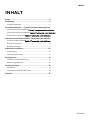
INHALT
Inhalt .............................................................................................. 2
Einführung.................................................................................... 3
VerpackungsInhalt ................................................................................. 3
Sicherheitshinweise ....... Fehler! Textmarke nicht definiert.
Sicherheit bei der InstallationFehler! Textmarke nicht definiert.
Sicherheit nach der InstallationFehler! Textmarke nicht definiert.
Elektrischer C anschlussFehler! Textmarke nicht definiert.
Mechanische InstallationFehler! Textmarke nicht definiert.
Vor dem ZusammenbauFehler! Textmarke nicht definiert.
Einbau mit Spinlock ............................................................................... 4
Bündige Montage ................................................................................... 9
Elektrische Installation ............................................................ 10
Pinbelegung ............................................................................................ 10
Verbindungsschemas ...........................................................................11
Konfiguration ..............................................................................12
Standard-Sensorkalibrierung ........................................................... 12
Kalibrierung anpassen ......................................................................... 12
Technische Daten ..................................................................... 14
Datenblatt................................................................................................. 14
Unterstützte NMEA 0183-Daten .................................................. 14
Zubehör....................................................................................... 15

EINFÜHRUNG
B000856
EINFÜHRUNG
VERPACKUNGSINHALT
1x
Professioneller
Ruderlagenanzeiger
B00067401
1x Kabelbaum
A2C1507870001
1x
Spinlock
-
Befestigungsmutter
A2C1376090001
1x Sicherheitshinweise
B000100
La pagina si sta caricando...
La pagina si sta caricando...
La pagina si sta caricando...
La pagina si sta caricando...
La pagina si sta caricando...
La pagina si sta caricando...
La pagina si sta caricando...
La pagina si sta caricando...
La pagina si sta caricando...
La pagina si sta caricando...
La pagina si sta caricando...
La pagina si sta caricando...
La pagina si sta caricando...
La pagina si sta caricando...
La pagina si sta caricando...
La pagina si sta caricando...
La pagina si sta caricando...
La pagina si sta caricando...
La pagina si sta caricando...
La pagina si sta caricando...
La pagina si sta caricando...
La pagina si sta caricando...
La pagina si sta caricando...
La pagina si sta caricando...
La pagina si sta caricando...
La pagina si sta caricando...
La pagina si sta caricando...
La pagina si sta caricando...
La pagina si sta caricando...
La pagina si sta caricando...
La pagina si sta caricando...
La pagina si sta caricando...
La pagina si sta caricando...
La pagina si sta caricando...
La pagina si sta caricando...
La pagina si sta caricando...
La pagina si sta caricando...
La pagina si sta caricando...
La pagina si sta caricando...
La pagina si sta caricando...
La pagina si sta caricando...
La pagina si sta caricando...
La pagina si sta caricando...
La pagina si sta caricando...
La pagina si sta caricando...
-
 1
1
-
 2
2
-
 3
3
-
 4
4
-
 5
5
-
 6
6
-
 7
7
-
 8
8
-
 9
9
-
 10
10
-
 11
11
-
 12
12
-
 13
13
-
 14
14
-
 15
15
-
 16
16
-
 17
17
-
 18
18
-
 19
19
-
 20
20
-
 21
21
-
 22
22
-
 23
23
-
 24
24
-
 25
25
-
 26
26
-
 27
27
-
 28
28
-
 29
29
-
 30
30
-
 31
31
-
 32
32
-
 33
33
-
 34
34
-
 35
35
-
 36
36
-
 37
37
-
 38
38
-
 39
39
-
 40
40
-
 41
41
-
 42
42
-
 43
43
-
 44
44
-
 45
45
-
 46
46
-
 47
47
-
 48
48
-
 49
49
-
 50
50
-
 51
51
-
 52
52
-
 53
53
-
 54
54
-
 55
55
-
 56
56
-
 57
57
-
 58
58
-
 59
59
-
 60
60
-
 61
61
-
 62
62
-
 63
63
-
 64
64
-
 65
65


veratron Professional Rudder Angle Indicator Manuale utente
- Tipo
- Manuale utente
in altre lingue
Documenti correlati
Altri documenti
-
Garmin GHP Reactor™ Hydraulic Autopilot Guida d'installazione
-
Garmin GWS™ 10 with GMI™ 10 Guida d'installazione
-
Volvo Penta IPS 600 Manuale utente
-
Furuno SC33 Manuale utente
-
 Volvo Penta D4 Manuale utente
-
Garmin 010-00701-01 Manuale utente
-
 NorthStar Navigation W310 Manuale utente
-
Simrad AP44 Istruzioni per l'uso

