
Betriebsanleitung | Operating instructions | Notice d’instruction
Istruzioni per l'uso | Instrucciones de servicio | Bruksanvisning
R412013434-BAL-001-AH
2021-07, Replaces: 2018-10
DE/EN/FR/IT/ES/SV
AVENTICS™ AS1 / AS2 / AS3 / AS5
Druckregelventil (RGS/RGP), Filterdruckregelventil (FRE)
Pressure regulator valve (RGS/RGP), filter pressure regulator valve (FRE)
Régulateur de pression (RGS/RGP), filtre régulateur de pression (FRE)
Valvola riduttrice di pressione (RGS/RGP), filtro riduttore di pressione (FRE)
Válvula reguladora de presión (RGS/RGP), válvula reguladora de presión con filtro
(FRE)
Tryckregulator (RGS och RGP), filterregulator (FRE)

AVENTICS™ AS1 / AS2 / AS3 / AS5 | R412013434-BAL-001-AH | Deutsch 2
Inhaltsverzeichnis
1 Zu dieser Dokumentation.................................................................................................................................................................................................. 3
1.1 Zusätzliche Dokumentationen.......................................................................................................................................................................................... 3
1.2 Darstellung von Informationen ......................................................................................................................................................................................... 3
1.2.1 Warnhinweise .................................................................................................................................................................................................... 3
1.2.2 Symbole............................................................................................................................................................................................................. 3
2 Sicherheit .......................................................................................................................................................................................................................... 3
2.1 Zu diesem Kapitel ............................................................................................................................................................................................................. 3
2.2 Allgemeine Sicherheitshinweise........................................................................................................................................................................................ 3
2.3 Bestimmungsgemäße Verwendung.................................................................................................................................................................................. 3
2.4 Qualifikation des Personals ............................................................................................................................................................................................... 3
2.5 Produkt- und technologieabhängige Sicherheitshinweise................................................................................................................................................. 3
3 Lieferumfang..................................................................................................................................................................................................................... 4
4 Produktbeschreibung........................................................................................................................................................................................................ 4
5 Montage, Inbetriebnahme und Betrieb.............................................................................................................................................................................. 4
5.1 Befestigungselemente W01–W05 montieren.................................................................................................................................................................. 4
5.2 Manometer montieren...................................................................................................................................................................................................... 4
5.2.1 Manometer mit radialer Dichtung...................................................................................................................................................................... 4
5.2.2 Manometer mit axialer (Metall-) Dichtung.......................................................................................................................................................... 4
5.3 Druck einstellen............................................................................................................................................................................................................... 4
5.4 Handrad abschließen ........................................................................................................................................................................................................ 4
5.4.1 AS1 .................................................................................................................................................................................................................... 4
5.4.2 AS2 – AS5........................................................................................................................................................................................................... 4
5.4.3 AS1 – AS5 (E11).................................................................................................................................................................................................. 4
5.5 Halb- und vollautomatischer Kondensatablass.................................................................................................................................................................. 5
5.5.1 Halbautomatischer Kondensatablass ................................................................................................................................................................. 5
5.5.2 Vollautomatischer Kondensatablass................................................................................................................................................................... 5
6 Demontage, Austausch ..................................................................................................................................................................................................... 5
6.1 Manometer austauschen .................................................................................................................................................................................................. 5
6.2 Filter austauschen............................................................................................................................................................................................................. 5
7 Erweiterung und Umbau.................................................................................................................................................................................................... 6
7.1 Durchflussrichtung ändern (AS2, AS3, AS5) ...................................................................................................................................................................... 6
7.1.1 Filterdruckregelventil (FRE) und Druckregelventil (RGS und RGP) umbauen ....................................................................................................... 6
7.1.2 Manometer und Gehäusedeckel wechseln | Serie AS2, AS3, AS5 ....................................................................................................................... 6
7.1.3 Behälter drehen (AS2, AS3, AS5) ........................................................................................................................................................................ 6
7.1.4 Umbau Druckregelventil mit durchgehender Druckversorgung ......................................................................................................................... 6
8 Reinigung und Pflege......................................................................................................................................................................................................... 6
9 Entsorgung........................................................................................................................................................................................................................ 6
10 Fehlersuche und Fehlerbehebung...................................................................................................................................................................................... 6
11 Technische Daten .............................................................................................................................................................................................................. 6
12 Anhang.............................................................................................................................................................................................................................. 6

1 Zu dieser Dokumentation
Lesen Sie diese Dokumentation vollständig und insbesondere das Kapitel g2.Si-
cherheit, bevor Sie mit dem Produkt arbeiten.
Diese Anleitung enthält wichtige Informationen, um das Produkt sicher und sach-
gerecht zu montieren, zu bedienen, zu warten und einfache Störungen selbst zu
beseitigen.
1.1 Zusätzliche Dokumentationen
Neben dieser Dokumentation erhalten Sie keine weiteren Unterlagen zum Pro-
dukt oder zur Anlage bzw. Maschine, in die das Produkt eingebaut wird.
Zusätzlich immer folgende Vorschriften beachten:
• Allgemein gültige, gesetzliche und sonstige verbindliche Regelungen der eu-
ropäischen bzw. nationalen Gesetzgebung.
• Gültige Vorschriften zur Unfallverhütung und zum Umweltschutz.
1.2 Darstellung von Informationen
1.2.1 Warnhinweise
Warnungen vor Personen- und Sachschäden werden in dieser Dokumentation
besonders hervorgehoben. Die beschriebenen Maßnahmen zur Gefahrenabwehr
müssen eingehalten werden.
Darstellung als Hervorhebungskasten
Warnhinweise werden zum einen in Form von Hervorhebungskästen dargestellt
mit folgendem Aufbau:
SIGNALWORT
Art und Quelle der Gefahr
Folgen bei Nichtbeachtung
uMaßnahmen zur Gefahrenabwehr
Darstellung mit hervorgehobenem Signalwort
In Handlungsanweisungen und Auflistungen sind Warnhinweise oftmals in den
Text integriert. Sie werden mit einem fett hervorgehobenen Signalwort eingelei-
tet:
VORSICHT! Zulässige Biegeradien nicht überschreiten.
Bedeutung der Signalwörter
Signalwort Bedeutung
Gefahr Unmittelbar drohende Gefahr für das Leben und die Gesundheit von
Personen.
Das Nichtbeachten dieser Hinweise hat schwere gesundheitliche
Auswirkungen zur Folge, bis hin zum Tod.
Warnung Möglicherweise drohende Gefahr für das Leben und die Gesundheit
von Personen.
Das Nichtbeachten dieser Hinweise kann schwere gesundheitliche
Auswirkungen zur Folge haben, bis hin zum Tod.
Vorsicht Möglicherweise gefährliche Situation.
Das Nichtbeachten dieser Hinweise kann leichte Verletzungen zur
Folge haben oder zu Sachbeschädigungen führen.
Achtung Möglichkeit von Sachbeschädigungen oder Funktionsstörungen.
Das Nichtbeachten dieser Hinweise kann Sachbeschädigungen oder
Funktionsstörungen zur Folge haben, jedoch keine Personenschä-
den.
1.2.2 Symbole
Empfehlung für den optimalen Einsatz unserer Produkte.
Beachten Sie diese Informationen, um einen möglichst reibungslosen
Betriebsablauf zu gewährleisten.
2 Sicherheit
2.1 Zu diesem Kapitel
Das Produkt wurde gemäß den allgemein anerkannten Regeln der Technik her-
gestellt. Trotzdem besteht die Gefahr von Personen- und Sachschäden, wenn Sie
dieses Kapitel und die Sicherheitshinweise in dieser Dokumentation nicht beach-
ten.
• Lesen Sie dieses Kapitel sowie die gesamte Dokumentation gründlich und
vollständig, bevor Sie mit dem Produkt arbeiten.
• Bewahren Sie die Dokumentation so auf, dass sie jederzeit für alle Benutzer
zugänglich ist.
• Geben Sie das Produkt an Dritte stets zusammen mit den erforderlichen Do-
kumentationen weiter.
2.2 Allgemeine Sicherheitshinweise
• Gültige Vorschriften zur Unfallverhütung und zum Umweltschutz im Verwen-
derland und am Arbeitsplatz beachten.
• AVENTICS Produkte nur in technisch einwandfreiem Zustand verwenden.
• Das Produkt auf offensichtliche Mängel, wie beispielsweise Risse im Gehäuse
oder fehlende Schrauben, Abdeckkappen, Dichtungen prüfen.
• Das Produkt grundsätzlich nicht verändern oder umbauen. Die Gewährleis-
tung erlischt bei fehlerhafter Montage.
• Personen, die AVENTICS Produkte montieren, bedienen, demontieren oder
warten, dürfen nicht unter dem Einfluss von Alkohol, sonstigen Drogen oder
Medikamenten, die die Reaktionsfähigkeit beeinflussen, stehen.
• Das Produkt unter keinen Umständen in unzulässiger Weise mechanisch be-
lasten.
• Warnungen und Angaben zum Produkt dürfen nicht mit Farbe etc. überdeckt
werden, sondern müssen stets gut lesbar sein.
2.3 Bestimmungsgemäße Verwendung
• Das Produkt darf erst in Betrieb genommen werden, wenn es in die Maschine/
die Anlage, für die es bestimmt ist, eingebaut ist.
• Technische Daten und genannte Betriebsbedingungen und Leistungsgrenzen
einhalten.
• Als Medium ausschließlich Druckluft verwenden.
Das Produkt ist für den professionellen Gebrauch und nicht für die private Ver-
wendung bestimmt.
• Die bestimmungsgemäße Verwendung schließt auch ein, dass diese Anlei-
tung und insbesondere das Kapitel g2.Sicherheit vollständig gelesen wurde.
2.4 Qualifikation des Personals
Die in dieser Dokumentation beschriebenen Tätigkeiten erfordern grundlegende
Kenntnisse in folgenden Bereichen sowie Kenntnisse der zugehörigen Fachbegrif-
fe:
• Mechanik
• Pneumatik
• Elektrik
Um die sichere Verwendung zu gewährleisten, dürfen daher die in dieser Doku-
mentation beschriebenen Tätigkeiten nur von einer entsprechenden Fachkraft
oder einer unterwiesenen Person unter Leitung einer Fachkraft durchgeführt wer-
den.
Eine Fachkraft ist, wer aufgrund seiner fachlichen Ausbildung, seiner Kenntnisse
und Erfahrungen sowie seiner Kenntnisse der einschlägigen Bestimmungen die
ihm übertragenen Arbeiten beurteilen, mögliche Gefahren erkennen und geeig-
nete Sicherheitsmaßnahmen treffen kann. Eine Fachkraft muss die einschlägigen
fachspezifischen Regeln einhalten.
2.5 Produkt- und technologieabhängige Sicherheitshinweise
• Kabel und Leitungen so verlegen, dass diese nicht beschädigt werden und nie-
mand darüber stolpern kann.
• Das Produkt nicht in aggressiver Umgebungsluft, z. B. Lösungsmitteldämpfe,
betreiben.
Die in der folgenden Tabelle exemplarisch aufgeführten Substanzen, die Lö-
sungsmittel in unterschiedlicher Konzentration enthalten, können im Einsatzbe-
reich von Druckluftaufbereitungsgeräten und im Ansaugbereich der Druckluft-
kompressoren zu einer aggressiven Umgebungsluft/Druckluft führen.
Lösungsmittel Aceton, Verdünnungsmittel für Farben, Alko-
hole, Ester.
Reinigungsmittel Trichlorethylen, Perchlorethylen, Benzol,
Benzin.
Sonstige Mittel Synthetische Öle, Bohröl, hochlegierte Öle,
bestimmte Kompressorenöle, Bremsflüssig-
keit, Ammoniak, Kleb- und Dichtungsmittel,
Weichmacher, Frostschutzmittel, Kühl-/
Schmiermittel.
AVENTICS™ AS1 / AS2 / AS3 / AS5 | R412013434-BAL-001-AH | Deutsch 3

VORSICHT! Ein unter Druck stehender Polycarbonat-Behälter kann durch aggres-
sive Umgebungsluft/Druckluft korrodieren und infolgedessen explodieren.
Ist die Anwesenheit der in der Tabelle genannten Substanzen nicht zu vermeiden,
z. B. in Klebemaschinen oder Vulkanisieranlagen, ist der Einsatz von Metallbehäl-
tern notwendig.
• Falls ein Öler zum Einsatz kommt, ausschließlich ein geeignetes Pneumatiköl
verwenden.
• Auf oder in den Filtern, Behältern oder Sichtfenstern darf sich kein Schmutz
ansammeln.
Behälter austauschen, wenn der Schmutz am Ablass nicht entfernt werden
kann (Ablass kann sonst verstopfen).
Bitte beachten Sie auch die „Kundeninformation zur Materialbeständigkeit in der
Druckluftaufbereitung“ (MNR R412025273)
3 Lieferumfang
• 1x Druckregelventil oder Filterdruckregelventil (siehe: Bestellung)
• Optional: Manometer lose beigelegt
• 1x Betriebsanleitung
4 Produktbeschreibung
Druckregel- und Filterdruckregelventile sind Komponenten von Wartungseinhei-
ten. Diese Ventile dienen zur Reduzierung des anstehenden Systemdrucks auf
einen maximalen, geregelten Betriebsdruck.
Filterdruckregelventile sind eine kompakte Einheit und dienen zusätzlich noch
zur Grobfilterung der Druckluft.
5 Montage, Inbetriebnahme und Betrieb
VORSICHT
Verletzungsgefahr durch Montage unter Druck oder Spannung!
Die Montage unter Druck oder anliegender elektrischer Spannung kann zu Ver-
letzungen führen und das Produkt oder Anlagenteile beschädigen.
1. Vor der Montage den relevanten Anlagenteil drucklos und spannungsfrei
schalten.
2. Die Anlage gegen Wiedereinschalten sichern.
VORSICHT
Schlagartiger Druckanstieg bei Inbetriebnahme!
Wird keine Befülleinheit SSU verwendet, steht bei Inbetriebnahme die Anlage
schlagartig unter Druck! Hierdurch kann es zu gefährlichen, ruckartigen Zylin-
derbewegungen kommen.
uSicherstellen, dass bei Inbetriebnahme einer Anlage ohne Befülleinheit SSU
die Zylinder in Endstellung stehen oder von Zylindern, die nicht in Endstel-
lung stehen, keine Gefahr ausgehen kann.
VORSICHT
Anlage steht im Betrieb unter Druck!
Bei unsachgemäßer Installation kann es zur Beschädigung des Produkts und
schweren Verletzungen kommen.
uVor Inbetriebnahme alle Verbindungen, Anschlüsse und Wartungsgeräte
auf korrekte Installation prüfen.
5.1 Befestigungselemente W01–W05 montieren
Siehe gAbb.8 bis gAbb.12
5.2 Manometer montieren
Siehe gAbb.1 (I)
Wird kein Manometer montiert, muss die Verschlussschraube in das
Druckregelventil eingeschraubt und abgedichtet werden.
Die Verschlussschraube muss separat bestellt werden.
5.2.1 Manometer mit radialer Dichtung
1. Manometer handfest in das Manometergewinde drehen, bis die Dichtung
komplett in das Gewinde eingeschraubt ist.
2. Manometer mit einem Maulschlüssel (SW14) min. 1/2 Umdrehung anziehen
und gleichzeitig optisch ausrichten.
5.2.2 Manometer mit axialer (Metall-) Dichtung
Bei separater Bestellung des Manometers wird der Quetschring als se-
parates Teil mitgeliefert.
1. Quetschring auf das Manometer stecken.
2. Manometer in das Manometergewinde eindrehen, bis der Quetschring bün-
dig an der Dichtfläche aufliegt.
3. Verbindung abdichten und gleichzeitig das Manometer durch Anziehen um
max. eine Umdrehung (Maulschlüssel SW14) ausrichten. Max. Anzugsmo-
ment: 7–8 Nm.
Vor Inbetriebnahme
uDas Produkt vor der Inbetriebnahme einige Stunden akklimatisieren lassen.
Ansonsten kann sich Kondenswasser im Gehäuse niederschlagen.
uSicherstellen, dass alle elektrischen und pneumatischen Anschlüsse belegt
oder verschlossen sind.
Nur ein vollständig installiertes Produkt in Betrieb nehmen.
5.3 Druck einstellen
Siehe gAbb.2
1. Handrad(a) nach oben ziehen.
2. Durch Drehen des Handrads(a) den gewünschten Druck einstellen.
3. Handrad(a) nach unten drücken. Das Handrad ist dadurch wieder arretiert.
Zum erneuten Einstellen des Drucks müssen die Sicherungsösen kom-
plett eingefahren sein.
Sicherungsösen einfahren
uDen oberen Kranz des Handrands nach rechts drehen, bis die Sicherungsösen
komplett eingefahren sind.
5.4 Handrad abschließen
Siehe gAbb.3
Um ein unbefugtes Ändern der Druckeinstellung zu verhindern, kann das
Handrad des Druckregelventils durch einen Schlüssel(AS1) bzw. ein Vorhänge-
schloss (AS2–AS5) gesichert werden.
5.4.1 AS1
Handrad abschließen:
uSchlüssel nach rechts drehen und abziehen.
Handrad aufschließen:
uSchlüssel nach links drehen und abziehen.
5.4.2 AS2 – AS5
Vorhängeschloss befestigen:
1. Handrad(a) nach unten drücken.
2. Oberen Kranz(b) des Handrads nach links in die Verriegelungsstellung dre-
hen.
Die Sicherungsösen(c) werden ausgefahren.
3. Vorhängeschloss in eine der Sicherungsösen(c) einhängen und schließen.
5.4.3 AS1 – AS5 (E11)
Version mit E11-Schließung
Auslieferung erfolgt ohne Schlüssel. Schlüssel muss separat bestellt
werden.
Handrad abschließen:
uSchlüssel nach rechts drehen und abziehen.
Handrad aufschließen:
uSchlüssel nach links drehen und abziehen.
AVENTICS™ AS1 / AS2 / AS3 / AS5 | R412013434-BAL-001-AH | Deutsch 4

Die Präzisions-Druckregelventile RGP und einige Druckregelventile
RGS geben den Eigenluftverbrauch permanent an die Umgebung ab.
Bei diesem Vorgang wird ein Leckagegeräusch erzeugt.
5.5 Halb- und vollautomatischer Kondensatablass
VORSICHT
Mögliche Beeinträchtigung der Druckluftanlage durch Kondensat!
Beim halbautomatischen Kondensatablass wird Kondensat nur abgelassen,
wenn der Behälter drucklos ist. Bei längerem Betrieb kann das Kondensat den
maximalen Füllstand übersteigen und in die Druckluftanlage gelangen. Dies
kann zur Beschädigung der Druckluftanlage führen.
1. Regelmäßig den Füllstand im Sammelbehälter kontrollieren.
2. Kondensat manuell ablassen, wenn das Kondensat den maximalen Füll-
stand erreicht hat.
3. Kondensat nicht unkontrolliert in die Umgebung ablassen.
5.5.1 Halbautomatischer Kondensatablass
Siehe gAbb.4 (I)
Der Kondensatablass öffnet und schließt in Abhängigkeit vom Betriebsdruck:
• Druck <1,5bar: Ablass geöffnet
• Druck >1,5bar: Ablass geschlossen
Halbautomatikbetrieb einstellen
uAblassschraube ganz nach links aufdrehen.
Die Schraube kann eine Umdrehung im Gewinde bleiben oder ganz entfernt
werden.
Kondensat manuell ablassen
Siehe gAbb.4 (III)
Das Kondensat kann auch manuell abgelassen werden (b=maximaler Füllstand).
1. Ablassschraube(a) ganz nach rechts drehen (geschlossen).
2. Ablassschraube(a) einige Umdrehungen nach links drehen, bis Kondensat ab-
fließt.
5.5.2 Vollautomatischer Kondensatablass
Siehe gAbb.4 (II)
Den vollautomatischen Kondensatablass gibt es in den Ausführungen „drucklos
offen“ und „drucklos geschlossen“. Bei beiden Ausführungen öffnet das Ventil
selbsttätig, sobald der Schwimmer seinen Höchststand erreicht, und schließt
wieder beim Erreichen des Tiefststands.
Ausführung „drucklos offen“
Der Kondensatablass öffnet und schließt in Abhängigkeit vom Betriebsdruck:
• Druck <1,5bar: Ablass geöffnet
• Druck >1,5bar: Ablass geschlossen
Automatikbetrieb einstellen
uAblassschraube ganz nach rechts bis zum Anschlag drehen.
Ausführung „drucklos geschlossen“
Der Kondensatablass ist unabhängig vom Betriebsdruck geschlossen.
Kondensat manuell ablassen
Siehe gAbb.4 (III)
Das Kondensat kann auch manuell abgelassen werden (b=maximaler Füllstand).
uAblassschraube(a) nach links bis zum Anschlag drehen.
Bei ganz nach links eingedrehter Ablassschraube ist die Ablassautoma-
tik gesperrt.
6 Demontage, Austausch
VORSICHT
Verletzungsgefahr durch Demontage unter Druck oder Spannung!
Die Demontage unter Druck oder anliegender elektrischer Spannung kann zu
Verletzungen führen und das Produkt oder Anlagenteile beschädigen.
1. Vor der Demontage den relevanten Anlagenteil drucklos und spannungs-
frei schalten.
2. Die Anlage gegen Wiedereinschalten sichern.
6.1 Manometer austauschen
gAbb.1 (II)
1. Das alte Manometer aus dem Manometergewinde drehen.
2. Das neue Manometer wie im Abschnitt g5.2.Manometer montieren be-
schrieben montieren.
6.2 Filter austauschen
VORSICHT
Anlage steht im Betrieb unter Druck!
Beim Öffnen der Anlage unter Druck kann es zu Verletzungen und zur Beschä-
digung des Produkts kommen.
uSicherstellen, dass die Anlage nicht unter Druck steht, bevor der Behälter
geöffnet wird.
INFO: Die eingesetzten Filter setzen sich mit der Zeit zu und müssen regelmäßig
ausgewechselt werden, spätestens nach einem Jahr.
Dies ist jedoch nur ein Richtwert, da die Intervalle von der Qualität der Druckluft
und dem Luftdurchsatz abhängen.
Verwenden Sie zur Bestellung die nachfolgend aufgeführten Materialnummern.
Die Adressen der Landesvertretungen finden Sie unter www.emerson.com/con-
tactus.
Tab.1: Verschleißteile
Serie AS Material-Nr.
Standard-Filterelement, 5µm,
Material: Polyethylen
AS1/AS2 1829207061
AS3 1829207068
AS5 R961403328
Standard-Filterelement, 25µm,
Material: Polyethylen
AS1/AS2 R961400004
AS3 R961400005
AS5 R961400006
Standard-Filterelement, 40µm,
Material: Polyethylen
AS1/AS2 R961403385
AS3 R961400142
AS5 R961403332
Standard-Filterelement, 40µm,
Material: Sinterbronze
AS1 R961400009
Vorgehen Serie AS1 FRE
Siehe gAbb.5
1. Relevanten Anlagenteil drucklos schalten und Anlage entlüften.
2. Behälter entgegen dem Uhrzeigersinn herausdrehen (a, b).
3. Filterstück herausdrehen (c, d).
4. Obere Drallkappe entfernen und Filtereinsatz wechseln (e).
5. Einzelteile wieder zusammensetzen (f).
6. Neuen Filtereinsatz eindrehen und von Hand leicht anziehen (g).
7. Behälter im Uhrzeigersinn bis auf Anschlag einschrauben (h, i).
8. Erneut Druck auf die Anlage geben.
Vorgehen Serie AS2 AS3 AS5 FRE
Siehe gAbb.6
1. Relevanten Anlagenteil drucklos schalten und Anlage entlüften.
AVENTICS™ AS1 / AS2 / AS3 / AS5 | R412013434-BAL-001-AH | Deutsch 5

2. Entriegelung (a) nach unten ziehen, Behälter erst nach links drehen (b) und
dann abziehen (c).
3. Filterteller herausdrehen (d).
4. Filtereinsatz wechseln (e).
5. Filterteller zusammen mit dem neuen Filter wieder eindrehen (f) und von
Hand leicht anziehen (g).
6. Behälter um 45° verdreht einsetzen (h) und nach rechts drehen, bis die Entrie-
gelung hörbar einrastet (i).
7. Erneut Druck auf die Anlage geben.
7 Erweiterung und Umbau
VORSICHT
Verletzungsgefahr bei Erweiterung und Umbau unter Druck oder Spannung!
Erweiterung und Umbau unter Druck oder anliegender elektrischer Spannung
kann zu Verletzungen führen und das Produkt oder Anlagenteile beschädigen.
1. Relevanten Anlagenteil drucklos und spannungsfrei schalten, bevor das
Produkt erweitert oder umgebaut wird.
2. Anlage gegen Wiedereinschalten sichern.
7.1 Durchflussrichtung ändern (AS2, AS3, AS5)
Bei der Serie AS1 ist kein Umbau nötig. Die Ausführung „Durchfluss
rechts/links“ hat eine eigene Bestellnummer.
Im Auslieferungszustand ist die Durchflussrichtung von links (1,IN) nach rechts
(2,OUT). Soll die Durchflussrichtung geändert werden, sind folgende Umbauten
am Produkt nötig:
7.1.1 Filterdruckregelventil (FRE) und Druckregelventil (RGS und
RGP) umbauen
Bei allen Komponenten erfolgt die Änderung der Durchflussrichtung durch einen
um 180° in der Vertikalachse gedrehten Einbau. Hierfür müssen die Gehäusede-
ckel und die Manometer gewechselt werden.
7.1.2 Manometer und Gehäusedeckel wechseln | Serie AS2, AS3,
AS5
Siehe gAbb.7
1. Das montierte Manometer entfernen, indem es links aus dem Gewinde her-
ausgedreht wird.
2. Blindstopfen lösen und auf der Gegenseite einschrauben.
3. Seitliche Abdeckkappen der Druckluftanschlüsse entfernen, indem mit geeig-
netem Werkzeug unter die Flügel der Abdeckkappen gefahren wird, diese
vorsichtig aufgehebelt und abgezogen werden.
4. Vordere und hintere Abdeckkappe anheben, indem die Einrastbolzen (je 2 auf
jeder Seite) der Schnappverschlüsse nach oben gedrückt werden.
VORSICHT! Abdeckkappen vorsichtig und gleichmäßig entfernen, damit die
4 Einrastbolzen nicht abbrechen.
5. Vordere und hintere Abdeckkappe gleichmäßig anheben, indem diese mit ei-
nem geeigneten Werkzeug vorsichtig weiter aufgehebelt und abgezogen
werden.
6. Abdeckkappen auf den Gegenseiten in umgekehrter Reihenfolge montieren.
Die Abdeckkappe mit dem AVENTICS-Logo soll nach vorne zeigen.
7. Manometer auf der Gegenseite einschrauben (siehe Kapitel g5.2.Manome-
ter montieren)
8. Blindstopfen auf der Gegenseite einschrauben.
7.1.3 Behälter drehen (AS2, AS3, AS5)
1. Behälter lösen.
2. Behälter um 180° drehen und wieder einrasten lassen.
Die Entriegelung zeigt nun nach vorne.
7.1.4 Umbau Druckregelventil mit durchgehender Druckversorgung
Bei den Druckregelventilen und Präzisions-Druckregelventilen mit
durchgehender Druckversorgung RGS-DS und RGP-DS ist kein Umbau
nötig. Bei diesen Geräten kann die Luft sowohl von links als auch von
rechts eingespeist werden.
8 Reinigung und Pflege
• Alle Öffnungen mit geeigneten Schutzeinrichtungen verschließen, damit kein
Reinigungsmittel ins System eindringen kann.
• Niemals Lösemittel oder aggressive Reinigungsmittel verwenden.
• Keine Hochdruckreiniger verwenden.
• Keine Druckluft zum Reinigen (Abblasen) von Wartungseinheit oder War-
tungsgeräten verwenden.
9 Entsorgung
Entsorgen Sie das Produkt nach den nationalen Bestimmungen Ihres Landes.
10 Fehlersuche und Fehlerbehebung
Störung Mögliche Ursache Abhilfe
Druck-/Durchflussniveau wird
nicht erreicht oder baut sich
langsam ab.
Filter verschmutzt
Filter zu klein gewählt
Filter reinigen bzw. ersetzen
Größeren Filter wählen
11 Technische Daten
Dieses Kapitel enthält einen Auszug der wichtigsten Technischen Daten. Weitere
Technische Daten finden Sie im Online-Katalog.
Allgemein
Spezifikation
Einbaulage Filterdruckregelventil: senkrecht
Druckregelventil: beliebig
Mediums-/ Umge-
bungstemperatur
min.…max.
-10°C…+50°C
Max. Eigenluftver-
brauch
RGP: 2,6 l/min
RGS: 1,5 l/min
Maximal zulässiger Druck, Temperaturbereich und Gewindeanschluss sind auf
den Produkten angegeben.
12 Anhang
Abbildungen: Ansicht variiert je nach Serie.
III III
Abb.1: I: Manometer montieren, II: Manometer austauschen | Serie AS2, AS3,
AS5
III: Integriertes Manometer | Serie AS1
AVENTICS™ AS1 / AS2 / AS3 / AS5 | R412013434-BAL-001-AH | Deutsch 6

FRE, RGS, RGP RGS-DS, RGP-DS
Abb.2: Druck einstellen (P1 = Eingangsdruck, P2 = Ausgangsdruck) | Serie AS1,
AS2, AS3, AS5
b
c
a
AS1 AS2, AS3, AS5
AS2, AS3, AS5
Abb.3: Druckregelventil abschließen
b
a
III III
Abb.4: Kondensatablass | Serie AS1, AS2, AS3, AS5
I: Halbautomatischer Kondensatablass, II: Vollautomatischer Kondensatablass, III:
Kondensat manuell ablassen
a
b
c
d
e
fg
hi
Abb.5: Filter austauschen |
Serie AS1 FRE
Serie AS1 FLP/FLC/FLA
a
b
c
d
e
f
gh
i
Abb.6: Filter austauschen |
Serie AS2, AS3, AS5 FRE
AVENTICS™ AS1 / AS2 / AS3 / AS5 | R412013434-BAL-001-AH | Deutsch 7

Abb.7: Filterdruckregelventil (FRE) und Druckregelventil (RGS und RGP) umbau-
en
Serie AS2, AS3, AS5
Abb.8: W01 | Befestigung mit Befestigungsplatte
Abb.9: W02 | Befestigung mit Befestigungswinkel
Abb.10: W03 | Verblockung und Befestigung mit Befestigungsbügel
Abb.11: W04| Verblockung mit Verblockungssatz
AVENTICS™ AS1 / AS2 / AS3 / AS5 | R412013434-BAL-001-AH | Deutsch 8

Abb.12: W05 | Verblockung und Befestigung mit Verblockungssatz
AVENTICS™ AS1 / AS2 / AS3 / AS5 | R412013434-BAL-001-AH | Deutsch 9

AVENTICS™ AS1 / AS2 / AS3 / AS5 | R412013434-BAL-001-AH | English 10
Contents
1 About This Documentation................................................................................................................................................................................................ 11
1.1 Additional documentation................................................................................................................................................................................................ 11
1.2 Presentation of information .............................................................................................................................................................................................. 11
1.2.1 Warnings............................................................................................................................................................................................................ 11
1.2.2 Symbols ............................................................................................................................................................................................................. 11
2 Safety................................................................................................................................................................................................................................ 11
2.1 About this chapter ............................................................................................................................................................................................................ 11
2.2 General safety instructions................................................................................................................................................................................................ 11
2.3 Intended use..................................................................................................................................................................................................................... 11
2.4 Personnel qualifications .................................................................................................................................................................................................... 11
2.5 Safety instructions related to the product and technology................................................................................................................................................ 11
3 Scope of delivery ............................................................................................................................................................................................................... 12
4 Product description ........................................................................................................................................................................................................... 12
5 Assembly, commissioning and operation........................................................................................................................................................................... 12
5.1 Mounting fastening elements W01–W05........................................................................................................................................................................ 12
5.2 Mounting the pressure gauge ........................................................................................................................................................................................... 12
5.2.1 Pressure gauge with radial seal........................................................................................................................................................................... 12
5.2.2 Pressure gauge with axial (metal) seal ................................................................................................................................................................ 12
5.3 Adjusting the pressure..................................................................................................................................................................................................... 12
5.4 Locking the handwheel ..................................................................................................................................................................................................... 12
5.4.1 AS1 .................................................................................................................................................................................................................... 12
5.4.2 AS2 – AS5........................................................................................................................................................................................................... 12
5.4.3 AS1 – AS5 (E11).................................................................................................................................................................................................. 12
5.5 Semi- and fully automatic condensate drain...................................................................................................................................................................... 13
5.5.1 Semi-automatic condensate drain...................................................................................................................................................................... 13
5.5.2 Fully automatic condensate drain....................................................................................................................................................................... 13
6 Disassembly, exchange...................................................................................................................................................................................................... 13
6.1 Replacing the pressure gauge ........................................................................................................................................................................................... 13
6.2 Exchanging the filter ......................................................................................................................................................................................................... 13
7 Conversion and extension.................................................................................................................................................................................................. 14
7.1 Changing the flow direction (AS2, AS3, AS5)..................................................................................................................................................................... 14
7.1.1 Converting the filter pressure regulator valve (FRE) and pressure regulator valve (RGS and RGP)........................................................................ 14
7.1.2 Changing the pressure gauge and housing cover | Series AS2, AS3, AS5 ............................................................................................................ 14
7.1.3 Rotating the reservoir (AS2, AS3, AS5) ............................................................................................................................................................... 14
7.1.4 Pressure regulator valve conversion with continuous pressure supply ............................................................................................................... 14
8 Cleaning and servicing....................................................................................................................................................................................................... 14
9 Disposal............................................................................................................................................................................................................................. 14
10 Troubleshooting................................................................................................................................................................................................................ 14
11 Technical data ................................................................................................................................................................................................................... 14
12 Appendix........................................................................................................................................................................................................................... 14

1 About This Documentation
Read this documentation completely, especially chapterg2.Safety before work-
ing with the product.
These instructions contain important information on the safe and appropriate as-
sembly, operation, and maintenance of the product and how to remedy simple
malfunctions yourself.
1.1 Additional documentation
In addition to this documentation, you will obtain further documents on the
product or the machine/system where it is installed.
uObserve all documents supplied with the system or machine.
Additionally always observe the following regulations:
• General, statutory and other binding rules of the European and national laws.
• Applicable regulations for accident prevention and environmental protection.
1.2 Presentation of information
1.2.1 Warnings
Warnings of personal injury and damage to property are highlighted in this docu-
mentation. The measures described to avoid these hazards must be followed.
Display as highlighted box
Warnings are displayed in the form of highlighted boxes with the following struc-
ture:
SIGNAL WORD
Hazard type and source
Consequences of non-observance
uPrecautions
Presentation with highlighted signal word
Instructions and lists often contain warnings that are integrated into the text.
They are introduced with a bold signal word:
CAUTION! Do not exceed permissible bending radii.
Meaning of the signal words
Signal word Meaning
DANGER Immediate danger to the life and health of persons.
Failure to observe these notices will result in serious health conse-
quences, including death.
Warning Possible danger to the life and health of persons.
Failure to observe these notices can result in serious health conse-
quences, including death.
Caution Possible dangerous situation.
Failure to observe these notices may result in minor injuries or dam-
age to property.
Notice Possibility of damage to property or malfunction.
Failure to observe these notices may result in damage to property or
malfunctions, but not in personal injury.
1.2.2 Symbols
Recommendation for the optimum use of our products.
Observe this information to ensure the smoothest possible operation.
2 Safety
2.1 About this chapter
The product has been manufactured according to the accepted rules of current
technology. Even so, there is danger of injury and damage to equipment if the
following chapter and safety instructions of this documentation are not followed.
• Read this chapter and this documentation completely before working with
the product.
• Keep this documentation in a location where it is accessible to all users at all
times.
• Always include the documentation when you pass the product on to third par-
ties.
2.2 General safety instructions
• Observe the valid regulations for accident prevention and environmental pro-
tection for the country where the device is used and at the workplace.
• Only use AVENTICS products that are in perfect working order.
• Examine the product for obvious defects, such as cracks in the housing or
missing screws, caps, or seals.
• Do not modify or convert the product. The warranty will not apply if the prod-
uct is incorrectly assembled.
• Persons who assemble, operate, disassemble, or maintain AVENTICS products
must not consume any alcohol, drugs, or pharmaceuticals that may affect
their ability to respond.
• Do not place any improper mechanical loads on the product under any cir-
cumstances.
• Product warnings and information must be legible, i.e. not covered by paint,
etc.
2.3 Intended use
• The product may only be commissioned after it has been installed in the ma-
chine/system for which it is intended.
• Observe the technical data and the listed specified operating conditions and
performance limits.
• Only use Compressed air as the medium.
The product is intended for professional use only.
• Intended use includes having read and understood these instructions com-
pletely, especially the section “Notes on Safety”.
2.4 Personnel qualifications
The work described in this documentation requires basic knowledge in the fol-
lowing areas, as well as knowledge of the appropriate technical terms:
• Mechanics
• Pneumatics
• Electrics
In order to ensure safe use, these activities described in this documentation may
therefore only be carried out by qualified technical personnel or an instructed
person under the direction and supervision of qualified personnel.
Qualifiedpersonnel are those who can recognize possible dangers and institute
the appropriate safety measures, due to their professional training, knowledge,
and experience, as well as their understanding of the relevant regulations per-
taining to the work to be done. Qualified personnel must observe the rules rele-
vant to the subject area.
2.5 Safety instructions related to the product and technology
• Lay cables and lines so that they cannot be damaged and no one can trip over
them.
• Do not operate the product in aggressive ambient air (e.g., solvent vapors).
The substances listed as examples in the following table, which contain solvents
in various concentrations, can lead to an aggressive ambient air/compressed air
in the application area of compressed air preparation devices and in the suction
area of air compressors.
Solvents Acetone, paint thinners, alcohols, ester.
Detergents Trichloroethylene, perchloroethylene, ben-
zene, gasoline.
Other substances Synthetic oils, drilling oil, high-alloyed oils,
certain compressor oils, brake fluid, ammo-
nia, bonding and sealing agents, plasticizers,
anti-freeze, coolants/lubricants.
CAUTION! A pressurized polycarbonate reservoir may corrode in an aggressive
ambient air/compressed air and explode as a result.
If the presence of the substances stated in the table cannot be avoided, such as in
gluing machines or vulcanization plants, the use of metal reservoirs is required
• If a lubricator is used, only use a suitable pneumatic oil.
AVENTICS™ AS1 / AS2 / AS3 / AS5 | R412013434-BAL-001-AH | English 11

• No soiling may be allowed to collect on or in the filters, reservoirs or windows.
Replace reservoirs if soiling cannot be removed from the drain (drain may be-
come clogged).
Also observe the “Customer information on material resistance in compressed air
preparation” (MNR R412025273)
3 Scope of delivery
• 1x Pressure regulator valve or filter pressure regulator valve (see: Order)
• Optional: Pressure gauge enclosed separately
• 1x Operating instructions
4 Product description
Pressure regulator valves and filter pressure regulator valves are components of
maintenance units. These valves serve to reduce the applied system pressure to a
maximum, regulated working pressure.
Filter pressure regulator valves form a compact unit and are also used for coarse
compressed air filtering.
5 Assembly, commissioning and operation
CAUTION
Danger of injury if assembled under pressure or voltage!
Assembling when under pressure or voltage can
lead to injuries and damage to the product or system components.
1. Make sure the relevant system part is without voltage or pressure prior to
assembly.
2. Protect the system against being restarted.
CAUTION
Sudden pressure increase during commissioning!
The system is exposed to sudden pressure on commissioning if no SSU filling
unit is used! This may result in dangerous erratic cylinder motions.
uWhen commissioning a system without an SSU filling unit, make sure that
the cylinders are in their end position. For cylinders not in the end position,
make sure they do not present any danger.
CAUTION
System is operating under pressure!
Incorrect installation could damage the product and cause serious injury.
uBefore commissioning, check that all connections, ports and maintenance
equipment have been correctly installed.
5.1 Mounting fastening elements W01–W05
See gFig.8 to gFig.12
5.2 Mounting the pressure gauge
See gFig.1 (I)
If a pressure gauge is not mounted, the blanking screw must be
screwed into the pressure regulator valve and sealed.
The blanking screw must be ordered separately.
5.2.1 Pressure gauge with radial seal
1. Firmly screw the pressure gauge by hand into the pressure gauge thread until
the seal is completely screwed into the thread.
2. Tighten the pressure gauge with an open-end wrench (SW14) by at least a
1/2 turn and align it visually at the same time.
5.2.2 Pressure gauge with axial (metal) seal
If the pressure gauge was ordered separately, the compression ring is
supplied as a separate part.
1. Mount the compression ring on the pressure gauge.
2. Turn the pressure gauge into the pressure gauge thread until the compression
ring is flush against the sealing face.
3. Seal off the connection while aligning the pressure gauge at the same time by
tightening with max. one turn (open-end wrench SW14). Max. tightening
torque 7–8Nm.
Before commissioning
uLet the product acclimatize for several hours before commissioning. Other-
wise, water may condense in the housing.
uCheck that all electrical and pneumatic connection ports are connected or
plugged.
Only operate a fully installed product.
5.3 Adjusting the pressure
See gFig.2
1. Pull the handwheel(a) up.
2. Turn the handwheel(a) to set the desired pressure.
3. Push down the handwheel(a). This relocks the handwheel.
The safety eyelets need to be retracted fully for any pressure readjust-
ment.
Retracting the safety eyelets
uTurn the top rim of the handwheel clockwise until the safety eyelets are fully
retracted.
5.4 Locking the handwheel
See gFig.3
To prevent any unauthorized change of the pressure setting, the pressure regula-
tor valve handwheel can be locked using a key(AS1) or a padlock (AS2–AS5).
5.4.1 AS1
To lock handwheel:
uTurn key clockwise and then pull it out.
To unlock hand wheel:
uTurn key counterclockwise and then pull it out.
5.4.2 AS2 – AS5
To attach padlock:
1. Push down the handwheel(a).
2. Turn the top rim(b) of the handwheel in counterclockwise direction to lock-
ing position.
This extends the safety eyelets(c).
3. Hang the padlock into one of the safety eyelets(c) and lock it.
5.4.3 AS1 – AS5 (E11)
Version with E11 locking
Supplied without key. Key must be ordered separately.
To lock handwheel:
uTurn key clockwise and then pull it out.
To unlock handwheel:
uTurn key counterclockwise and then pull it out.
RGP precision pressure regulator valves and some RGS pressure regu-
lator valves permanently release the internal air consumption to the
atmosphere. A leakage noise is emitted during this process.
AVENTICS™ AS1 / AS2 / AS3 / AS5 | R412013434-BAL-001-AH | English 12

5.5 Semi- and fully automatic condensate drain
CAUTION
Potential impairment of compressed air system by condensate!
In the case of the semi-automatic condensate drain, condensate is only dis-
charged when the reservoir is not under pressure. If in operation for an ex-
tended period, the condensate may exceed the maximum filling level and find
its way into the compressed air system. This may result in damage to the com-
pressed air system.
1. Regularly check the filling level in the reservoir.
2. Drain condensate manually once it reaches the maximum filling level.
3. Do not allow the condensate to enter the environment in an uncontrolled
manner.
5.5.1 Semi-automatic condensate drain
See gFig.4 (I)
The condensate drain opens and closes depending on operating pressure:
• Pressure <1.5bar: drain open
• Pressure >1.5bar: drain closed
Setting the semi-automatic mode
uTurn the drain screw all the way counterclockwise.
You may leave the screw one turn deep in the thread or remove it completely.
Draining condensate manually
See gFig.4 (III)
The condensate can also be manually drained (b=maximum filling level).
1. Turn the drain screw(a) all the way clockwise (closed position).
2. Turn the drain screw(a) counterclockwise a few turns until condensate runs
out.
5.5.2 Fully automatic condensate drain
See gFig.4 (II)
The fully automatic condensate drain is available in versions “open without pres-
sure” and “closed without pressure”. In both versions the valve opens automati-
cally as soon as the floater reaches the highest point and closes again when the it
reaches the lowest point.
Version “open without pressure”
The condensate drain opens and closes depending on operating pressure:
• Pressure <1.5bar: drain open
• Pressure >1.5bar: drain closed
Setting the automatic mode
uTurn the drain screw clockwise as far as it will go.
Version “closed without pressure”
The condensate drain is closed regardless of the operating pressure.
Draining condensate manually
See gFig.4 (III)
The condensate can also be manually drained (b=maximum filling level).
uTurn the drain screw(a) counterclockwise as far as it will go.
If the drain screw is screwed in all the way anti-clockwise, the auto-
matic drainage is blocked.
6 Disassembly, exchange
CAUTION
Danger of injury if disassembled under pressure or voltage!
Disassembling when under pressure or voltage can lead to injuries and damage
to the product or system parts.
1. Make sure the relevant system part is without voltage or pressure prior to
disassembly.
2. Protect the system against being restarted.
6.1 Replacing the pressure gauge
gFig.1 (II)
1. Unscrew the old pressure gauge from the pressure gauge thread.
2. Mount the new pressure gauge as described in the g5.2.Mounting the pres-
sure gauge section.
6.2 Exchanging the filter
CAUTION
System is operating under pressure!
Opening the system while under pressure may damage the product and cause
personal injury.
uEnsure that the system is not under pressure before you open the reservoir.
INFO: The filters clog up over time and need to be replaced regularly, at the lat-
est after a year.
This, however, is just a guidance value, since the intervals depend on the com-
pressed air quality and airflow rate.
Use the material numbers below when placing your orders. The addresses of the
international agencies are available at www.emerson.com/contactus.
Table1: Wearing parts
AS series Material no.
Standard filter element, 5µm,
material: polyethylene
AS1/AS2 1829207061
AS3 1829207068
AS5 R961403328
Standard filter element, 25µm,
material: polyethylene
AS1/AS2 R961400004
AS3 R961400005
AS5 R961400006
Standard filter element, 40µm,
material: polyethylene
AS1/AS2 R961403385
AS3 R961400142
AS5 R961403332
Standard filter element, 40µm,
material: sintered bronze
AS1 R961400009
Procedure for series AS1 FRE
See gFig.5
1. Make sure the relevant system part is not under pressure and exhaust the sys-
tem.
2. Turn reservoir counterclockwise and remove(a,b).
3. Screw out the filter piece (c, d).
4. Remove the top twist cap and replace the filter insert(e).
5. Reassemble the individual parts (f).
6. Screw in a new filter insert and tighten gently by hand(g).
7. Screw in the reservoir as far as it will go in a clockwise direction (h,i).
8. Apply pressure to the system again.
Procedure for series AS2 AS3 AS5 FRE
See gFig.6
1. Make sure the relevant system part is not under pressure and exhaust the sys-
tem.
2. Pull the release (a) downward, then turn the reservoir at first counterclock-
wise (b) and then remove (c).
3. Screw out the filter disk (d).
4. Replace filter insert (e).
5. Screw the filter disk back in together with the new filter (f) and tighten gently
by hand (g).
6. Insert the reservoir rotated by 45° (h) and turn clockwise until the release en-
gages audibly (i).
7. Apply pressure to the system again.
AVENTICS™ AS1 / AS2 / AS3 / AS5 | R412013434-BAL-001-AH | English 13

7 Conversion and extension
CAUTION
Danger of injury if extension or conversion work is performed under pres-
sure or voltage!
Extension and conversion when under pressure or electrical voltage can lead to
injuries and damage to the product or system parts.
1. Make sure that the relevant system part is without pressure and voltage be-
fore extending or converting the product.
2. Protect the system against being restarted.
7.1 Changing the flow direction (AS2, AS3, AS5)
No conversion is necessary on the AS1 series. The “right/left flow” ver-
sion has a separate order number.
On delivery the flow direction is from left (1,IN) to right (2,OUT). The following
conversion on the product is necessary if the flow direction is to be changed:
7.1.1 Converting the filter pressure regulator valve (FRE) and pres-
sure regulator valve (RGS and RGP)
On all components, the flow direction change is performed by rotating an instal-
lation by 180° around the vertical axis. The housing cover and pressure gauge
need to be replaced for the purpose.
7.1.2 Changing the pressure gauge and housing cover | Series AS2,
AS3, AS5
See gFig.7
1. Remove the mounted pressure gauge by unscrewing it from the thread in a
counterclockwise direction.
2. Remove the blanking plug and screw it into the opposite side.
3. Remove the side cover caps on the compressed air connections by sliding a
suitable tool under the cover cap wings, carefully lifting them up and taking
them off.
4. Lift the front and rear cover cap by pushing the lock-in bolts (2 on each side)
up on the latches.
CAUTION! Remove the cover caps carefully and evenly so that the 4 lock-in
bolts do not break off.
5. Lift the front and rear caps evenly by carefully levering them open with a suit-
able tool and taking them off.
6. Mount the cover caps on the opposite sides in the reverse order.
The cover cap with the AVENTICS logo should be facing to the front.
7. Screw in the pressure gauge on the opposite side (see chapter g5.2.Mount-
ing the pressure gauge)
8. Screw the blanking plug into the opposite side.
7.1.3 Rotating the reservoir (AS2, AS3, AS5)
1. Remove the reservoir.
2. Rotate reservoir 180° and click it back into place.
The release is now pointing to the front.
7.1.4 Pressure regulator valve conversion with continuous pressure
supply
No conversion is required for pressure regulator valves and precision
pressure regulator valves RGS-DS and RGP-DS with continuous pres-
sure supply. On these devices, air can be supplied from the left as well
as the right.
8 Cleaning and servicing
• Close all openings with suitable safety devices so that no cleaning agent can
enter into the system.
• Never use solvents or aggressive detergents!
• Do not use high-pressure cleaners for cleaning!
• Do not use compressed air for cleaning (blowing off) the maintenance unit or
equipment.
9 Disposal
Dispose of the product in accordance with the national regulations in your coun-
try.
10 Troubleshooting
Malfunction Possible cause Remedy
Pressure/flow level is not
reached or drops off slowly.
Filter contaminated
Selected filter size too small
Clean or replace filter
Select larger filter
11 Technical data
This section contains an excerpt of the key technical data. Further technical data
can be found in the online catalog.
General
Specifications
Mounting orientation Filter pressure regulator valve: vertical
Pressure regulator valve: any
Medium/ambient
temperature min./
max.
min.…max.
-10–+50°C
Max. internal air con-
sumption
RGP: 2.6 l/min
RGS: 1.5 l/min
Maximum permissible pressure, temperature range, and thread connection are
indicated on the products.
12 Appendix
Figures: View varies according to the series.
III III
Fig.1: I: Mounting the pressure gauge, II: Replacing the pressure gauge | Series
AS2, AS3, AS5
III: Integrated pressure gauge | Series AS1
FRE, RGS, RGP RGS-DS, RGP-DS
Fig.2: Adjusting the pressure (P1 = input pressure, P2 = output pressure) | Series
AS1, AS2, AS3, AS5
AVENTICS™ AS1 / AS2 / AS3 / AS5 | R412013434-BAL-001-AH | English 14

b
c
a
AS1 AS2, AS3, AS5
AS2, AS3, AS5
Fig.3: Locking the pressure regulator valve
b
a
III III
Fig.4: Condensate drain | Series AS1, AS2, AS3, AS5
I: Semi-automatic condensate drain, II: Fully automatic condensate drain, III:
Manually draining condensate
a
b
c
d
e
fg
hi
Fig.5: Exchanging the filter |
Series AS1 FRE
Series AS1 FLP/FLC/FLA
a
b
c
d
e
f
gh
i
Fig.6: Exchanging the filter |
Series AS2, AS3, AS5 FRE
AVENTICS™ AS1 / AS2 / AS3 / AS5 | R412013434-BAL-001-AH | English 15

Fig.7: Converting the filter pressure regulator valve (FRE) and pressure regulator
valve (RGS and RGP)
Series AS2, AS3, AS5
Fig.8: W01 | Mounting with mounting plate
Fig.9: W02 | Mounting with mounting bracket
Fig.10: W03 | Block assembly and mounting with mounting clip
Fig.11: W04| Block assembly with block assembly kit
AVENTICS™ AS1 / AS2 / AS3 / AS5 | R412013434-BAL-001-AH | English 16

Fig.12: W05 | Block assembly and mounting with block assembly kit
AVENTICS™ AS1 / AS2 / AS3 / AS5 | R412013434-BAL-001-AH | English 17

AVENTICS™ AS1 / AS2 / AS3 / AS5 | R412013434-BAL-001-AH | Français 18
Sommaire
1 A propos de cette documentation...................................................................................................................................................................................... 19
1.1 Documentations complémentaires................................................................................................................................................................................... 19
1.2 Présentation des informations .......................................................................................................................................................................................... 19
1.2.1 Mises en garde ................................................................................................................................................................................................... 19
1.2.2 Symboles ........................................................................................................................................................................................................... 19
2 Sécurité............................................................................................................................................................................................................................. 19
2.1 À propos de ce chapitre..................................................................................................................................................................................................... 19
2.2 Consignes générales de sécurité ....................................................................................................................................................................................... 19
2.3 Utilisation conforme ......................................................................................................................................................................................................... 19
2.4 Qualification du personnel ................................................................................................................................................................................................ 19
2.5 Consignes de sécurité selon le produit et la technique ...................................................................................................................................................... 19
3 Fourniture ......................................................................................................................................................................................................................... 20
4 Description du produit....................................................................................................................................................................................................... 20
5 Montage, mise en service et fonctionnement .................................................................................................................................................................... 20
5.1 Montage des éléments de fixation W01 à W05 ................................................................................................................................................................. 20
5.2 Montage du manomètre................................................................................................................................................................................................... 20
5.2.1 Manomètre avec joint radial............................................................................................................................................................................... 20
5.2.2 Manomètre avec joint (métallique) axial ............................................................................................................................................................ 20
5.3 Réglage de la pression...................................................................................................................................................................................................... 20
5.4 Verrouillage du volant....................................................................................................................................................................................................... 20
5.4.1 AS1 .................................................................................................................................................................................................................... 20
5.4.2 AS2 – AS5........................................................................................................................................................................................................... 21
5.4.3 AS1 – AS5 (E11).................................................................................................................................................................................................. 21
5.5 Purge semi-automatique et entièrement automatique..................................................................................................................................................... 21
5.5.1 Purge semi-automatique.................................................................................................................................................................................... 21
5.5.2 Purge entièrement automatique........................................................................................................................................................................ 21
6 Démontage, remplacement............................................................................................................................................................................................... 21
6.1 Remplacement du manomètre ......................................................................................................................................................................................... 21
6.2 Remplacement des filtres.................................................................................................................................................................................................. 21
7 Transformation et extension.............................................................................................................................................................................................. 22
7.1 Modification du sens de débit (AS2, AS3, AS5) .................................................................................................................................................................. 22
7.1.1 Transformation du filtre régulateur de pression (FRE) et du régulateur de pression (RGS et RGP) ....................................................................... 22
7.1.2 Remplacement du manomètre et du couvercle de boîtier | Série AS2, AS3, AS5 ................................................................................................ 22
7.1.3 Rotation de la cuve (AS2, AS3, AS5).................................................................................................................................................................... 22
7.1.4 Transformation du régulateur de pression avec alimentation en pression continue............................................................................................ 22
8 Nettoyage et entretien ...................................................................................................................................................................................................... 22
9 Mise au rebut..................................................................................................................................................................................................................... 22
10 Recherche et élimination de défauts .................................................................................................................................................................................. 22
11 Données techniques .......................................................................................................................................................................................................... 22
12 Annexe.............................................................................................................................................................................................................................. 22

1 A propos de cette documentation
Lire entièrement la présente documentation et en particulier le chapitre g2.Sé-
curité avant de travailler avec le produit.
Cette notice d’instruction contient des informations importantes pour monter,
utiliser et entretenir le produit de manière sûre et conforme, ainsi que pour pou-
voir éliminer soi-même de simples interférences.
1.1 Documentations complémentaires
Outre la documentation, d’autres documents relatifs aux produits ou à l’installa-
tion / la machine dans laquelle le produit sera intégré sont fournis.
uRespecter tous les documents qui sont fournis avec l’installation ou la ma-
chine.
Dispositions à respecter systématiquement:
• Les dispositions légales ainsi que toute autre réglementation à caractère obli-
gatoire en vigueur et généralement applicable en Europe ainsi que dans le
pays d’utilisation.
• Les consignes de prévention d’accidents et de protection de l’environnement
applicables.
1.2 Présentation des informations
1.2.1 Mises en garde
Les avertissements relatifs à des dommages corporels ou matériels sont mis en
évidence dans cette documentation. Les mesures décrites pour éviter les dangers
doivent être respectées.
Représentation de l'encadré de mise en évidence
Les avertissements sont mis en évidence par le biais d’un encadré de mise en évi-
dence dont la structure est la suivante:
MOT-CLE
Type et source de danger
Conséquences en cas de non-respect
uMesures préventives contre le danger
Représentation avec mot-clé mis en évidence
Les instructions et les énumérations contiennent souvent des mentions d’avertis-
sement intégrées dans le texte. Ces mentions d’avertissement sont introduites
par un mot-clé en gras:
ATTENTION! Ne pas dépasser les rayons de courbure admissibles.
Signification des mots-clés
MOT-CLE Signification
Danger Danger imminent menaçant la vie et la santé de personnes.
Le non-respect de ces consignes entraîne de lourdes répercussions
sur la santé, voire la mort.
Avertissement Danger potentiellement imminent menaçant la vie et la santé de
personnes.
Le non-respect de ces consignes peut entraîner de lourdes répercus-
sions sur la santé, voire la mort.
Attention Situation potentiellement dangereuse.
Le non-respect de ces consignes peut entraîner des blessures légères
ou des dommages matériels.
Remarque Possibilité de dommages matériels ou de dysfonctionnements.
Le non-respect de ces consignes peut entraîner des dommages ma-
tériels ou des dysfonctionnements, mais pas de dommages corpo-
rels.
1.2.2 Symboles
Recommandation pour une utilisation optimale de nos produits.
Respecter ces informations afin de garantir le meilleur fonctionne-
ment possible.
2 Sécurité
2.1 À propos de ce chapitre
Le produit a été fabriqué selon les règles techniques généralement reconnues.
Des dommages matériels et corporels peuvent néanmoins survenir si ce chapitre
de même que les consignes de sécurité ne sont pas respectés.
• Lire ce chapitre ainsi que la présente documentation attentivement et com-
plètement avant d’utiliser le produit.
• Conserver cette documentation de sorte que tous les utilisateurs puissent y
accéder à tout moment.
• Toujours transmettre le produit à de tierces personnes accompagné des do-
cumentations nécessaires.
2.2 Consignes générales de sécurité
• Respecter les consignes de prévention d’accidents et de protection de l’envi-
ronnement applicables dans le pays d’utilisation et au poste de travail.
• Utiliser les produitsAVENTICS exclusivement lorsque leur état technique est
irréprochable.
• Contrôler si le produit présente des défauts visibles, comme par exemple des
fissures sur le boîtier et s’il manque des vis, couvercles, joints, etc.
• Il est interdit de modifier ou de transformer le produit. La garantie n’est plus
valable en cas de montage incorrect.
• Les personnes montant, commandant, démontant ou entretenant des pro-
duits AVENTICS ne doivent pas être sous l’emprise d’alcool, de drogues ou de
médicaments divers pouvant altérer leur temps de réaction.
• Ne surcharger en aucun cas le produit de manière mécanique de par une utili-
sation non conforme.
• Les avertissements et indications concernant le produit doivent rester lisibles
et ne pas être recouverts par de la peinture ou autre.
2.3 Utilisation conforme
• La mise en service du produit n’est autorisée que lorsque celui-ci est entière-
ment monté sur la machine ou l’installation à laquelle il a été destiné.
• Respecter les données techniques ainsi que les conditions de fonctionnement
et les limites de puissance indiquées.
• Comme fluide, utiliser uniquement de l’Air comprimé.
Le produit est destiné à un usage dans le domaine professionnel et non privé.
• L’utilisation conforme inclut aussi le fait d’avoir lu et compris la présente no-
tice dans son intégralité et en particulier le chapitre des consignes de sécurité.
2.4 Qualification du personnel
Les opérations décrites dans cette documentation exigent des connaissances
pneumatiques de base dans les domaines suivants, ainsi que la connaissance des
termes techniques qui y sont liés:
• Mécanique
• Pneumatique
• Électrique
Afin d’assurer une utilisation en toute sécurité, les travaux décrits dans la pré-
sente documentation ne doivent par conséquent être effectués que par des tech-
niciens dans ces domaines ou par une personne initiée mais restant sous la direc-
tion d’un technicien.
Un technicien est capable d’évaluer les tâches qui lui sont confiées, de recon-
naître d’éventuels dangers et de prendre les mesures de sécurité adéquates
grâce à sa formation spécialisée, ses connaissances et son expérience, ainsi qu’à
ses connaissances des directives en vigueur. Il doit respecter les règles spéci-
fiques en vigueur.
2.5 Consignes de sécurité selon le produit et la technique
• Poser les câbles et les conduites de sorte que ceux-ci ne soient pas endomma-
gés et que personne ne puisse trébucher dessus.
• Ne pas faire fonctionner le produit dans un air ambiant agressif, par exemple
vapeurs de solvants.
Les substances présentées à titre d'exemple dans le tableau suivant, qui
contiennent des solvants en différentes concentrations, peuvent générer un air
AVENTICS™ AS1 / AS2 / AS3 / AS5 | R412013434-BAL-001-AH | Français 19

ambiant/comprimé agressif si elles sont utilisées dans la zone d'exploitation des
appareils de préparation de l'air comprimé ou dans la zone d'aspiration des com-
presseurs d’air.
Solvants Acétone, diluant pour peinture, alcools, es-
ters.
Détergents Trichloréthylène, perchloroéthylène, ben-
zène, essence.
Autres flux Huiles de synthèse, huile de forage, huiles
fortement alliées, certaines huiles pour com-
presseurs, liquide de frein, ammoniac, adhé-
sifs et moyens d’étanchéité, plastifiants, anti-
gel, réfrigérants/lubrifiants.
ATTENTION! Une cuve en polycarbonate sous pression peut se corroder dû à un
air ambiant/comprimé agressif, et donc exploser.
Si la présence des substances mentionnées dans le tableau est inévitable, par ex.
dans des machines à coller ou des installations de vulcanisation, l'utilisation de
cuves en métal est requise.
• En cas d’utilisation d’un lubrificateur, utiliser exclusivement une huile pneu-
matique appropriée.
• Aucun dépôt de poussière ne doit s’accumuler dans et sur les filtres, cuves et
fenêtres.
Si la poussière est impossible à enlever au niveau de la purge, remplacer la
cuve (la purge pouvant se boucher).
Veuillez également tenir compte du document «Customer information regar-
ding material resistance in compressed air preparation» («Informations client sur
la résistance des matériaux en matière de traitement de l’air comprimé»)
(réf.R412025273)
3 Fourniture
• 1x Régulateur de pression ou filtre régulateur de pression (voir: Commande)
• En option: manomètre fourni non monté
• 1Notice d’instruction
4 Description du produit
Les régulateurs de pression et filtres régulateurs de pression sont des compo-
sants d’unités de traitement de l'air. Ils sont destinés à réduire la pression du sys-
tème présente à une pression de service maximale régulée.
Les filtres régulateurs de pression constituent une unité compacte et servent en
outre au filtrage sommaire de l’air comprimé.
5 Montage, mise en service et fonctionnement
ATTENTION
Risque de blessure dû à un montage sous pression ou sous tension!
Le montage sous pression ou sous tension électrique peut provoquer des bles-
sures et endommager le produit ou des parties de l’installation.
1. Mettre hors tension et hors pression la partie concernée de l’installation
avant le montage.
2. Protéger l’installation de toute remise en marche.
ATTENTION
Brusque augmentation de la pression lors de la mise en service!
Si aucune unité de mise en pression SSU n’est employée, l'installation est brus-
quement mise sous pression lors de la mise en service! Cela peut provoquer
des mouvements dangereux et saccadés du vérin.
uLors de la mise en service d'une installation sans unité de mise en pression
SSU, veiller à ce que les vérins se trouvent en position finale ou à ce que les
vérins qui ne sont pas en position finale ne présentent aucun danger.
ATTENTION
Lors du fonctionnement, l’installation est sous pression!
Une installation réalisée de manière non conforme risque d’endommager le
produit et de provoquer des blessures graves.
uAvant de procéder à la mise en service, vérifier si tous les raccords et appa-
reils de maintenance raccordés sont installés correctement.
5.1 Montage des éléments de fixation W01 à W05
Voir gFig.8 jusque gFig.12
5.2 Montage du manomètre
Voir gFig.1 (I)
Si aucun manomètre n'est monté, le bouchon à visser doit être vissé
dans le régulateur de pression et étanché.
Le bouchon à visser doit être commandé séparément.
5.2.1 Manomètre avec joint radial
1. Visser à la main le manomètre dans le filetage du manomètre jusqu’à ce que
le joint soit entièrement vissé dans le filetage.
2. Serrer le manomètre à l'aide d’une clé à fourche (taille 14) d'au moins 1/2ro-
tation tout en l'orientant à l'œil nu.
5.2.2 Manomètre avec joint (métallique) axial
En cas de commande séparée du manomètre, la bague de serrage est
fournie en tant que pièce séparée.
1. Insérer la bague de serrage sur le manomètre.
2. Visser le manomètre dans le filetage du manomètre jusqu'à ce que la bague
de serrage repose sur le joint d'étanchéité.
3. Étancher le raccord tout en orientant le manomètre en le serrant d'une rota-
tion maximum (clé à fourche, taille14). Couple de serrage max.: 7–8Nm.
Avant la mise en service
uAvant la mise en service du produit, laisser le produit s’acclimater pendant
quelques heures, de l’eau de condensation pouvant sinon se former dans le
boîtier.
uS'assurer que tous les raccordements électriques et pneumatiques sont affec-
tés ou fermés.
Ne mettre le produit en service que s'il est entièrement installé.
5.3 Réglage de la pression
Voir gFig.2
1. Tirer le volant(a) vers le haut.
2. Régler la pression souhaitée en tournant le volant(a).
3. Presser le volant(a) vers le bas. Cela permet de le bloquer à nouveau.
Pour refaire le réglage de la pression, il est nécessaire que les œillets de
sécurité soient totalement rétractés.
Rétractation des œillets de sécurité
uTourner la couronne supérieure du volant vers la droite jusqu’à ce que les
œillets de sécurité soient entièrement rétractés.
5.4 Verrouillage du volant
Voir gFig.3
Afin d'éviter un déréglage inopiné de la pression, il est possible de verrouiller le
volant du régulateur de pression à l'aide d'une clé(AS1) ou d'un cadenas(AS2 à
AS5).
5.4.1 AS1
Verrouillage du volant:
uTourner la clé vers la droite et la retirer.
Déverrouillage du volant:
uTourner la clé vers la gauche et la retirer.
AVENTICS™ AS1 / AS2 / AS3 / AS5 | R412013434-BAL-001-AH | Français 20
La pagina si sta caricando...
La pagina si sta caricando...
La pagina si sta caricando...
La pagina si sta caricando...
La pagina si sta caricando...
La pagina si sta caricando...
La pagina si sta caricando...
La pagina si sta caricando...
La pagina si sta caricando...
La pagina si sta caricando...
La pagina si sta caricando...
La pagina si sta caricando...
La pagina si sta caricando...
La pagina si sta caricando...
La pagina si sta caricando...
La pagina si sta caricando...
La pagina si sta caricando...
La pagina si sta caricando...
La pagina si sta caricando...
La pagina si sta caricando...
La pagina si sta caricando...
La pagina si sta caricando...
La pagina si sta caricando...
La pagina si sta caricando...
La pagina si sta caricando...
La pagina si sta caricando...
La pagina si sta caricando...
La pagina si sta caricando...
La pagina si sta caricando...
La pagina si sta caricando...
-
 1
1
-
 2
2
-
 3
3
-
 4
4
-
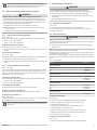 5
5
-
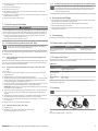 6
6
-
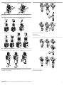 7
7
-
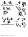 8
8
-
 9
9
-
 10
10
-
 11
11
-
 12
12
-
 13
13
-
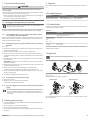 14
14
-
 15
15
-
 16
16
-
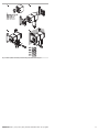 17
17
-
 18
18
-
 19
19
-
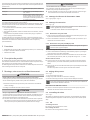 20
20
-
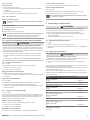 21
21
-
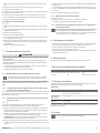 22
22
-
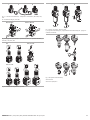 23
23
-
 24
24
-
 25
25
-
 26
26
-
 27
27
-
 28
28
-
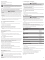 29
29
-
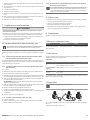 30
30
-
 31
31
-
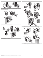 32
32
-
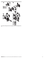 33
33
-
 34
34
-
 35
35
-
 36
36
-
 37
37
-
 38
38
-
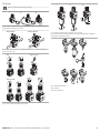 39
39
-
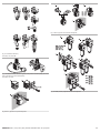 40
40
-
 41
41
-
 42
42
-
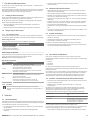 43
43
-
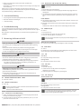 44
44
-
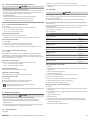 45
45
-
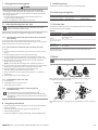 46
46
-
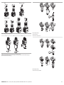 47
47
-
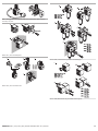 48
48
-
 49
49
-
 50
50


in altre lingue
- français: Emerson AS1 Manuel utilisateur
- español: Emerson AS1 Manual de usuario
- Deutsch: Emerson AS1 Benutzerhandbuch
- svenska: Emerson AS1 Användarmanual
Documenti correlati
Altri documenti
-
AVENTICS R961400142 Manuale del proprietario
-
-
-
-
-
AVENTICS Série NL1 / NL2 / NL3 / NL4 / NL6, Régulateur, filtre régulateur de pression Manuale del proprietario
-
-